Paper Menu >>
Journal Menu >>
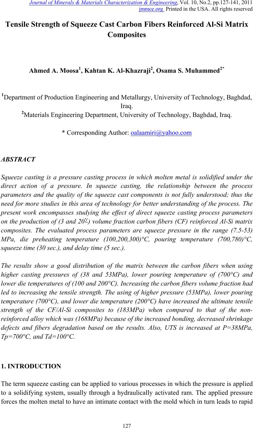 Journal of Minera ls & Materials Ch ar ac teri zatio n & Engineeri ng, Vol. 10, No.2, pp.127-141, 2011 jmmce.org Printed in the USA. All rights reserved 127 Tensile Strength of Squeeze Cast Carbon Fibers Reinforced Al-Si Matrix Composites Ahmed A. Moosa1, Kahtan K. Al-Khazraji2, Osama S. Muhammed2* 1Department of Production Engineering and Metallurgy, University of Technology, Baghdad, Iraq. 2Materials Engineering Department, University of Technology, Baghdad, Iraq. * Corresponding Author: oalaamiri@yahoo.com ABSTRACT Squeeze casting is a pressure casting process in which molten metal is solidified under the direct action of a pressure. In squeeze casting, the relationship between the process parameters and the quality of the squeeze cast components is not fully understood; thus the need for more studies in this area of technology for better understanding of the process. The present work encompasses studying the effect of direct squeeze casting process parameters on the production of (3 and 20٪) volume fraction carbon fibers (CF) reinforced Al-Si matrix composites. The evaluated process parameters are squeeze pressure in the range (7.5-53) MPa, die preheating temperature (100,200,300)°C, pouring temperature (700,780)°C, squeeze time (30 sec.), and delay time (5 sec.). The results show a good distribution of the matrix between the carbon fibers when using higher casting pressures of (38 and 53MPa), lower pouring temperature of (700°C) and lower die temperatures of (100 and 200°C). Increasing the carbon fibers volume fraction had led to increasing the tensile strength. The using of higher pressure (53MPa), lower pouring temperature (700°C), and lower die temperature (200°C) have increased the ultimate tensile strength of the CF/Al-Si composites to (183MPa) when compared to that of the non- reinforced alloy which was (168MPa) because of the increased bonding, decreased shrinkage defects and fibers degradation based on the results. Also, UTS is increased at P=38MPa, Tp=700°C, and Td=100°C. 1. INTRODUCTION The term squeeze casting can be applied to various processes in which the pressure is applied to a solidifying system, usually through a hydraulically activated ram. The applied pressure forces the molten metal to have an intimate contact with the mold which in turn leads to rapid 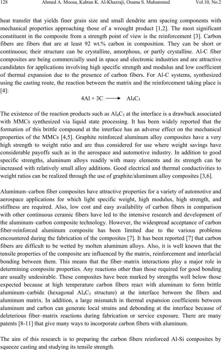 128 Ahmed A. Moosa, Kahtan K. Al-Khazraji, Osama S. Muhammed Vol.10, No.2 heat transfer that yields finer grain size and small dendrite arm spacing components with mechanical properties approaching those of a wrought product [1,2]. The most significant constituent in the composite from a strength point of view is the reinforcement [3]. Carbon fibers are fibers that are at least 92 wt.% carbon in composition. They can be short or continuous; their structure can be crystalline, amorphous, or partly crystalline. Al-C fiber composites are being commercially used in space and electronic industries and are attractive candidates for applications involving high specific strength and modulus and low coefficient of thermal expansion due to the presence of carbon fibers. For Al-C systems, synthesized using the casting route, the reaction between the matrix and the reinforcement taking place is [4]: 4Al + 3C Al4C3 The existence of the reaction products such as Al4C3 at the interface is a drawback associated with MMCs synthesized via liquid state processing. It has been widely reported that the formation of this brittle compound at the interface has an adverse effect on the mechanical properties of the MMCs [4,5]. Graphite reinforced aluminum alloy composites have a very high strength to weight ratio and are thus considered for use where weight savings have considerable payoffs such as in the aerospace and automotive industry. In addition to good specific strengths, aluminum alloys readily with many elements and its strength can be increased with relatively small alloy additions. Good electrical and thermal conductivities to weight ratios can be realized through the use of graphite/aluminum alloy composites [3,6]. Aluminum–carbon fiber composites have attractive properties for a variety of automotive and aerospace applications for which light specific weight, high modulus, high strength, and stiffness are required. Also, low cost and easy availability of carbon fibers in comparison with other continuous ceramic fibers have led to the intensive research and development of the aluminum–carbon composite technology. However, the widespread acceptance of carbon fiber-reinforced aluminum composite has been limited due to the various problems encountered during the fabrication of the composites [7]. It has been reported [7] that carbon fibers are difficult to be wetted by molten aluminum alloys. Also, it is well known that the tensile properties of the composite are influenced by the matrix, reinforcement and interfacial bonding between them. This means that the fiber–matrix interactions play a major role in determining composite properties. Any reactions other than those required for good bonding are usually undesirable. These composites have been marked by strengths well below those expected because at high temperature carbon fibers react with aluminum to form brittle aluminum–carbide (hexagonal Al4C3 structure) at the interface between the fibers and aluminum matrix. In addition, a large mismatch in thermal expansion coefficients between aluminum and carbon can generate local strains and debonding at the interface because of deleterious fiber–matrix reactions during fabrication or service exposure. There are many patents [8-11] that give many ways to incorporate carbon fibers with aluminum. The aim of this research is to preparing the carbon fibers reinforced Al-Si composites by squeeze casting and studying its tensile strength.  Vol.10, No.2 Tensile Strength of Squeeze Cast Carbon Fibers 129 2. EXPERIMENTAL PROCEDURES A standard aluminum-silicon eutectic alloy type 1725 DIN [12] is used in this work as the matrix of the composites. This alloy has good bearing properties, good fluidity and low coefficient of thermal expansion with a density of 2.68 g/cm3. It is a common alloy used in the production of pistons [13,14]. Table (1) illustrates the chemical composition of the alloy. The analysis was done by using the atomic absorption apparatus at the Ministry of Science and Technology in Baghdad, Iraq. Table (1) Chemical composition (wt٪) of the (Al-Si) alloy. Si Fe Cu Mn Mg Zn Ti Al 12.1 0.65 0.83 0.2 0.27 0.45 0.02 remainder A PAN-based carbon fiber bundles type HTA 5131 from the Tenax Fibers Company, Germany, were used as reinforcement in this work. Table (2) illustrates the characteristics of these fibers. Table (2) Characteristics of carbon fiber bundles. Characteristics Typical values Number of filaments 3000 Filament diameter 10 (μm) Density 1.76 (g/cm3) Tensile strength 3950 (MPa) Tensile modulus 238 (GPa) Elongation at break 1.7 (٪) Specific heat capacity 710 (J/KgK) Thermal conductivity 17 (W/mK) Coefficient of thermal expansion - 0.1 (10-6/K) Specific electrical resistance 1.6 * 10-3 (O-cm) The squeeze casting system comprises the hydraulic press, squeeze die and auxiliary equipments. A vertical hydraulic press is used (with a ram 70 mm in diameter) to apply the pressure in a perpendicular direction to the squeeze casting die. The press can apply a hydraulic pressure of (1-70) Kg/cm2, with a constant ram speed of 25 cm/min. The selected squeeze punch shown in Figure (1) was made of low alloy steel, and made with a hole in its upper part to be fixed to the ram with two steel bolts. The lower part of the punch is rectangular in shape with a semicircle ends. This lower part is used to squeeze the molten alloy. Figure (2) shows the squeeze die. The die is horizontal, made of low alloy steel and consists of two parts joined by four high temperature resistant steel bolts. This design allows the final  130 Ahmed A. Moosa, Kahtan K. Al-Khazraji, Osama S. Muhammed Vol.10, No.2 squeezed composite casting to be removed from the die easily. Two dies were used for the composites. The first has two holes on each side for the 3 vol. ٪ carbon fibers (two bundles), and the second has 21 holes on each side for the 20 vol. ٪ carbon fibers (21 bundles). Table (3) illustrates the chemical composition of the punch and dies which was done with the portable metals analyzer type 1650 from the ARUN Technology, Germany, available at the Department of Materials Engineering of the University of Technology in Baghdad, Iraq. Figure (1) The squeeze punch. Figure (2) The squeeze die. Table (3) Chemical composition of the punch and die steel. Element Weight Percent (٪) Element Weight Percent (٪) Fe 93.9 Co 0.02 C 1.0 Cu 0.585 Cr 2.84 Mo 0.06 Ni 0.936 Nb 0.01 Si 0.227 Ti 0.02 Mn 0.383 V 0.02 Al 0.0253 Sn 0.04 A local electrical melting furnace is used to melt the Al-Si alloy to the required temperatures. The maximum temperature of the furnace is 1200 ± 5 °C. A calibrated K- type thermocouple with an accuracy of ± 1°C is used to measure the temperature. This furnace was also used to heat the squeeze die before pressing. The Preparation of Carbon Fiber Reinforced Al-Si Matrix Composites involves the following steps: a) Carbon fiber bundles are first horizontally laid inside the squeeze die and fixed at its ends with using 0.21 gm and 1.49 gm to produce composites with two different volume fractions. b) A standard Al-Si alloy (199.79 and 198.51 gm) is melted in the furnace at the required temperature using an alumina crucible. 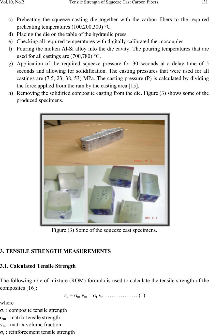 Vol.10, No.2 Tensile Strength of Squeeze Cast Carbon Fibers 131 c) Preheating the squeeze casting die together with the carbon fibers to the required preheating temperatures (100,200,300) °C. d) Placing the die on the table of the hydraulic press. e) Checking all required temperatures with digitally calibrated thermocouples. f) Pouring the molten Al-Si alloy into the die cavity. The pouring temperatures that are used for all castings are (700,780) °C. g) Application of the required squeeze pressure for 30 seconds at a delay time of 5 seconds and allowing for solidification. The casting pressures that were used for all castings are (7.5, 23, 38, 53) MPa. The casting pressure (P) is calculated by dividing the force applied from the ram by the casting area [15]. h) Removing the solidified composite casting from the die. Figure (3) shows some of the produced specimens. Figure (3) Some of the squeeze cast specimens. 3. TENSILE STRENGTH MEASUREMENTS 3.1. Calculated Tensile Strength The following role of mixture (ROM) formula is used to calculate the tensile strength of the composites [16]: σc = σm vm + σr vr ……………….(1) where σc : composite tensile strength σm : matrix tensile strength vm : matrix volume fraction σr : reinforcement tensile strength 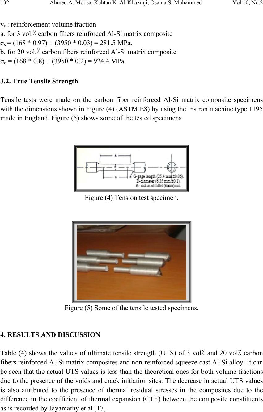 132 Ahmed A. Moosa, Kahtan K. Al-Khazraji, Osama S. Muhammed Vol.10, No.2 vr : reinforcement volume fraction a. for 3 vol.٪ carbon fibers reinforced Al-Si matrix composite σc = (168 * 0.97) + (3950 * 0.03) = 281.5 MPa. b. for 20 vol.٪ carbon fibers reinforced Al-Si matrix composite σc = (168 * 0.8) + (3950 * 0.2) = 924.4 MPa. 3.2. True Tensile Strength Tensile tests were made on the carbon fiber reinforced Al-Si matrix composite specimens with the dimensions shown in Figure (4) (ASTM E8) by using the Instron machine type 1195 made in England. Figure (5) shows some of the tested specimens. Figure (4) Tension test specimen. Figure (5) Some of the tensile tested specimens. 4. RESULTS AND DISCUSSION Table (4) shows the values of ultimate tensile strength (UTS) of 3 vol٪ and 20 vol٪ carbon fibers reinforced Al-Si matrix composites and non-reinforced squeeze cast Al-Si alloy. It can be seen that the actual UTS values is less than the theoretical ones for both volume fractions due to the presence of the voids and crack initiation sites. The decrease in actual UTS values is also attributed to the presence of thermal residual stresses in the composites due to the difference in the coefficient of thermal expansion (CTE) between the composite constituents as is recorded by Jayamathy et al [17].  Vol.10, No.2 Tensile Strength of Squeeze Cast Carbon Fibers 133 Table (4) Ultimate tensile strength (UTS) of carbon fiber reinforced Al-Si matrix composites Volume Fraction (٪) Squeeze Casting Conditions UTS(MPa) Tp (°C) Td (°C) P (MPa) 3 ٪ 780 300 7.5 68 23 88 38 80 53 75 200 7.5 92 23 104 38 139 53 134 100 7.5 116 23 157 38 167 53 162 700 300 7.5 111 23 146 38 148 53 144 200 7.5 117 23 158 38 178 * 53 183 * 100 7.5 127 23 161 38 170 * 53 176 * 20 ٪ 780 300 7.5 125 23 128 38 129 53 131 UTS of non-reinforced Al-Si alloy is 168 MPa *UTS higher than that of the non-reinforced Al-Si alloy Figure (6) shows some of the tested composites. The flat surface with no fiber pull-out in Figure (6a) reveals a strong bonding in the composites, while Figure (6b) shows a poorly bonded composite. When comparing the UTS of the squeeze cast composites with that of the non-reinforced Al- Si alloy, it can be seen that only four specimens (marked by stars in Table 4) give higher UTS than that of the Al-Si alloy. These higher UTS values are due to the contribution of carbon fibers and the squeeze casting conditions that led to good bonding with low quantity of aluminum carbide phase, lower porosity and higher hardness which result in higher UTS. The specimens that gave lower UTS than Al-Si alloy within the casting condition ranges evaluated in the present work, indicates that the carbon fibers reinforcement does not contribute appreciably to the tensile strength of the composites. This is because it gives excessive interfacial interactions (Al4C3 phase) which degrades the fiber strength. Also  134 Ahmed A. Moosa, Kahtan K. Al-Khazraji, Osama S. Muhammed Vol.10, No.2 it has coarse primary silicon, or the fibers are not aligned in the longitudinal centerline due to poor attachment or mostly the using of higher pressures. These results are in agreement with the work of Lancin & Marhic [5], Li & Chao [18] and Ryu et al [19]. Figure (6) Bonding in some specimens. The large amount of brittle Al4C3 phase may produce destructive notches (pits) on the surface of the fibers. Also the sliding of eutectic Si by the tensile stresses will notch the fibers. These pits are crack initiation sites, resulting in the embrittlement of the surrounding Al-Si matrix and the resulted failure of composites. This is in agreement with the findings of Lancin & Marhic [5] and Li & Chao[18]. The higher UTS was obtained at Tp = 700°C, Td = 200°C and P = 53MPa as shown in Figure (7). Figure (7) Good bonding in the specimen squeeze cast at Tp = 700°C, Td = 200°C and P = 53 MPa. It can be seen that it fails in a smooth surface without any fiber pull-out. This reveals the good fiber to matrix bonding with its lower content of aluminum carbide. It can be seen from Table (4) that increasing of volume fraction has led to slightly increasing the UTS when 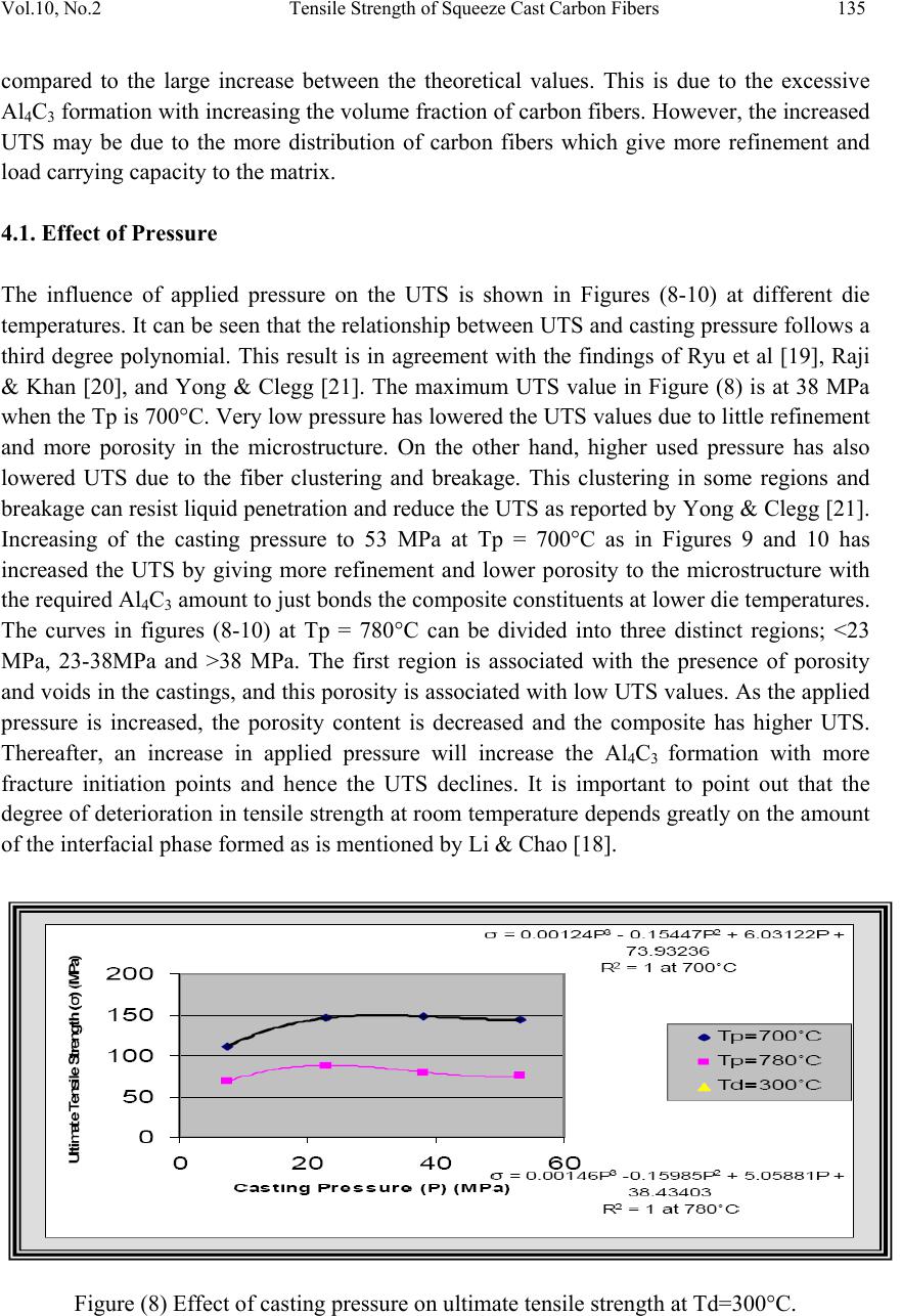 Vol.10, No.2 Tensile Strength of Squeeze Cast Carbon Fibers 135 compared to the large increase between the theoretical values. This is due to the excessive Al4C3 formation with increasing the volume fraction of carbon fibers. However, the increased UTS may be due to the more distribution of carbon fibers which give more refinement and load carrying capacity to the matrix. 4.1. Effect of Pressure The influence of applied pressure on the UTS is shown in Figures (8-10) at different die temperatures. It can be seen that the relationship between UTS and casting pressure follows a third degree polynomial. This result is in agreement with the findings of Ryu et al [19], Raji & Khan [20], and Yong & Clegg [21]. The maximum UTS value in Figure (8) is at 38 MPa when the Tp is 700°C. Very low pressure has lowered the UTS values due to little refinement and more porosity in the microstructure. On the other hand, higher used pressure has also lowered UTS due to the fiber clustering and breakage. This clustering in some regions and breakage can resist liquid penetration and reduce the UTS as reported by Yong & Clegg [21]. Increasing of the casting pressure to 53 MPa at Tp = 700°C as in Figures 9 and 10 has increased the UTS by giving more refinement and lower porosity to the microstructure with the required Al4C3 amount to just bonds the composite constituents at lower die temperatures. The curves in figures (8-10) at Tp = 780°C can be divided into three distinct regions; <23 MPa, 23-38MPa and >38 MPa. The first region is associated with the presence of porosity and voids in the castings, and this porosity is associated with low UTS values. As the applied pressure is increased, the porosity content is decreased and the composite has higher UTS. Thereafter, an increase in applied pressure will increase the Al4C3 formation with more fracture initiation points and hence the UTS declines. It is important to point out that the degree of deterioration in tensile strength at room temperature depends greatly on the amount of the interfacial phase formed as is mentioned by Li & Chao [18]. Figure (8) Effect of casting pressure on ultimate tensile strength at Td=300°C. 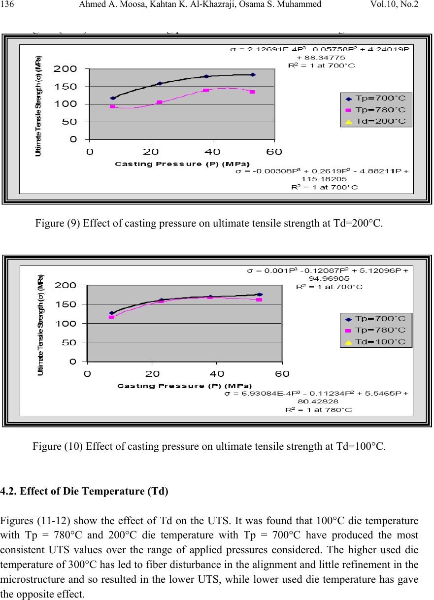 136 Ahmed A. Moosa, Kahtan K. Al-Khazraji, Osama S. Muhammed Vol.10, No.2 Figure (9) Effect of casting pressure on ultimate tensile strength at Td=200°C. Figure (10) Effect of casting pressure on ultimate tensile strength at Td=100°C. 4.2. Effect of Die Temperature (Td) Figures (11-12) show the effect of Td on the UTS. It was found that 100°C die temperature with Tp = 780°C and 200°C die temperature with Tp = 700°C have produced the most consistent UTS values over the range of applied pressures considered. The higher used die temperature of 300°C has led to fiber disturbance in the alignment and little refinement in the microstructure and so resulted in the lower UTS, while lower used die temperature has gave the opposite effect.  Vol.10, No.2 Tensile Strength of Squeeze Cast Carbon Fibers 137 Figure (11) Effect of die temperature on ultimate tensile strength at Tp=780°C. Figure (12) Effect of die temperature on ultimate tensile strength at Tp=700°C. 4.3. Effect of Pouring Temperature (Tp) The effect of pouring temperature on the UTS values is shown in Figures (8-10). It was found that a pouring temperature of 700°C supported all the used pressures in giving the highest UTS when compared to 780°C pouring temperature. This is because of the less variation in fiber disturbance, faster solidification, less contact time between the fibers and the matrix, refinement in the eutectic and Si particles and higher hardness. This behavior is consistent with the statement of Yue [22] and Baron et al [23]. It can be noted that lowering of Td can reduce the variations in UTS values since it leads to low Al4C3 amount. The effect of Al4C3 phase on the carbon fibers can be studied by using fracture mechanic analysis. Assuming there is a crack in the matrix and its tip is in contact with the fiber surface, this crack will propagate perpendicular to the fiber length under the tension loading as shown in Figure (13). 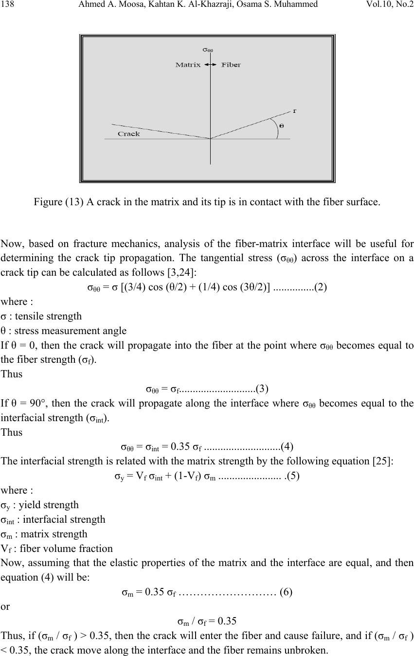 138 Ahmed A. Moosa, Kahtan K. Al-Khazraji, Osama S. Muhammed Vol.10, No.2 Figure (13) A crack in the matrix and its tip is in contact with the fiber surface. Now, based on fracture mechanics, analysis of the fiber-matrix interface will be useful for determining the crack tip propagation. The tangential stress (σθθ) across the interface on a crack tip can be calculated as follows [3,24]: σθθ = σ [(3/4) cos (θ/2) + (1/4) cos (3θ/2)] ...............(2) where : σ : tensile strength θ : stress measurement angle If θ = 0, then the crack will propagate into the fiber at the point where σθθ becomes equal to the fiber strength (σf). Thus σθθ = σf............................(3) If θ = 90°, then the crack will propagate along the interface where σθθ becomes equal to the interfacial strength (σint). Thus σθθ = σint = 0.35 σf ............................(4) The interfacial strength is related with the matrix strength by the following equation [25]: σy = Vf σint + (1-Vf) σm ....................... .(5) where : σy : yield strength σint : interfacial strength σm : matrix strength Vf : fiber volume fraction Now, assuming that the elastic properties of the matrix and the interface are equal, and then equation (4) will be: σm = 0.35 σf ……………………… (6) or σm / σf = 0.35 Thus, if (σm / σf ) > 0.35, then the crack will enter the fiber and cause failure, and if (σm / σf ) < 0.35, the crack move along the interface and the fiber remains unbroken.  Vol.10, No.2 Tensile Strength of Squeeze Cast Carbon Fibers 139 A tensile test was conducted on a fiber bundle pulled from one of the composites specimens. The resulting UTS value for the fiber was (86 MPa). It is clear that this value is very much lower than that of the UTS of the as received fiber bundle which was (3950 MPa). This proves the degradation has happened in the fibers after squeeze cast composite preparation. This degradation is due to the formation of Al4C3 phase and the expected formation of coarse silicon particles. Now, if we calculate matrix to fiber stress ratio as follows: σm / σf = (168 / 86) = 1.95 Then, it is clear that this ratio is greater than 0.35. This indicates that the fibers are broken as confirmed in Figure (14), and hence the lower values of UTS for most of the produced squeeze cast composites. The composite that gave higher UTS than that of the non-reinforced alloy was assumed to have stress ratio lower than 0.35, and its fibers were not highly degraded. Figure (14) Fractures in the carbon fibers which were pulled from the specimen squeeze cast at Tp=780°C, Td=300°C and P=38 MPa. 5. CONCLUSIONS 1. Using higher pressures, lower die temperatures and lower pouring temperatures have led to increasing the ultimate tensile strength of the CF/Al-Si composites because of increased bonding, decreased shrinkage defects and fiber degradation. 2. The squeeze cast CF/Al-Si composites produced at Tp = 700°C, Td = 200°C and P = 53 MPa have given the best tensile strength and hence they are the best combination of squeeze casting process parameters in the production of the used metal matrix composites.  140 Ahmed A. Moosa, Kahtan K. Al-Khazraji, Osama S. Muhammed Vol.10, No.2 REFERENCES [1] Vijian P., Arunachalam V.P., “Modelling and multi objective optimization of LM24 aluminum alloy squeeze cast process parameters using genetic algorithm” J. Mat. Proc. Tech., vol. 186, 2007, pp. 82-86. [2] Dionne S., “Influence of titanium diboride reinforcements on the microstructure, mechanical properties and fracture behavior of cast zincaluminum composites” Ph.D. thesis, department des mines et metallurgie, faculte des sciences et de genie, universite laval, Quebec, CANADA, sept. 1999. [3] Dixon Jr. R.G., “Microstructure/property relationships for carbon fiber reinforced aluminum alloys” M.Sc. thesis, Massachusetts Institute of Technology, June 1985. [4] Rohatgi P.K., Tiwari V., Gupta N., “Squeeze infiltration processing of nickel coated carbon fiber reinforced Al-2014 composite” J. Mat. Sci., vol. 41, Sept. 2006, pp. 7232- 7239. [5] Lancin M., Marhic C., “TEM study of carbon fiber reinforced aluminum matrix composites: influence of brittle phases and interface on mechanical properties” J. European Ceramic Society, vol. 20, Nov. 2000, pp. 1493- 1503. [6] He P., Liu Y.Z., Liu D., “Interfacial microstructure and forming mechanism of brazing Cf/Al composite with Al-Si filler” Mat. Sci. Eng., vol. A 422, Feb. 2006, pp. 333-338. [7] Daoud A., “Microstructure and tensile properties of 2014 Al alloy reinforced with continuous carbon fibers manufactured by gas pressure infiltration” Mat. Sci. Eng., vol. A391, 2005, pp. 114-120. [8] Levitt A.P., Band H.E., “Method of making metal impregnated graphite fibers” US Patent, no. 4157409, Jun./5/1979. [9] Donomoto T., Tanaka A., Tatematsu Y., Akai T., “Fiber reinforced metal type composite material with high purity aluminum alloy containing magnesium as matrix metal” US Patent, no. 4450207, May/22/1984. [10] Divecha A.P., Karmarkar S.d., “process for producing graphite fiber/aluminum- magnesium matrix composites” US Patent, no. 4578287, Mar./25/1986. [11] Kyono T., Ohnishi S., Hanano T., Hotta T., “Preform wire for a carbon fiber reinforced aluminum composite material and a method of manufacturing the same” US Patent, no. 208039, May/29/1990. [12] Hufnagel W., “Key to Aluminum alloys” Aluminum-Verlag, Düsseldorf, 1982, p. 119. [13] Maleki A., Niroumand B., Shafyei A., “Effects of squeeze casting parameters on density, macrostructure and hardness of LM13 alloy” Mat. Sci. Eng., vol. A428, 2006, pp. 135-140. [14] Takhakh A.M., “Solidification simulation and experimental investigation of Al-Si cast structures” Ph.D. thesis, Department of Production Engineering and Metallurgy, University of Technology, Baghdad, Iraq, 2007. [15] Schwam D., Wallace J.F., Chang Q., Zhu Y., “Optimization of the squeeze casting process for aluminum alloy parts” final report, Case Western Reserve University, OH, USA, July 2002. [16] Meyers M.A., Chawla K.K., “Mechanical behavior of materials” Prentice- Hall, Inc., USA, 1999, p. 644.  Vol.10, No.2 Tensile Strength of Squeeze Cast Carbon Fibers 141 [17] Jayamathy M., et.al., “Influence of reinforcement on microstructure and mechanical response of a magnesium alloy” Current Science, vol. 87, no. 9, nov. 2004, pp. 1218- 1231. [18] Li S.H., Chao C.G., “Effects of carbon fiber/Al interface on mechanical properties of carbon-fiber-reinforced aluminum-matrix composites” Met. & Mat. Trans. A, vol. 35A, July 2004, pp. 2153-2160. [19] Ryu Y.M., Yoon E.P., Rhee M.H., “NCG reinforced MMC fabricated by the squeeze casting method” App. Comp. Mat., vol. 7, 2000, pp. 251-267. [20] Raji A., Khan R.H., “Effects of pouring temperature and squeeze pressure on Al-8 ٪ Si alloy squeeze cast parts” AU J. T., vol. 9, no. 4, April 2006, pp. 229-237. [21] Yong M.S., Clegg A.J., “Process optimization for a squeeze cast magnesium alloy metal matrix composite” J. Mat. Proc. Tech., vol. 168, 2005, pp. 262-269. [22] Yue T.M., “Squeeze casting of high-strength aluminum wrought alloy AA7010” J. Mat. Proc. Tech., vol. 66, 1997, pp. 179-185. [23] Baron R.P., Wert J.A., Gerard D.A., Wawner F.E., “The processing and characterization of sintered metal-reinforced aluminum matrix composites” J. Mat. Sci, vol. 32, 1997, pp. 6435-6445. [24] Dieter G.E., “Mechanical Metallurgy” McGraw-Hill, Inc, USA, Second Edition, 1976, p. 258. [25] ASM Metals Handbook, “casting”, 9th edition, 4th printing, vol. 15, Materials park, OH, 1998. |