Paper Menu >>
Journal Menu >>
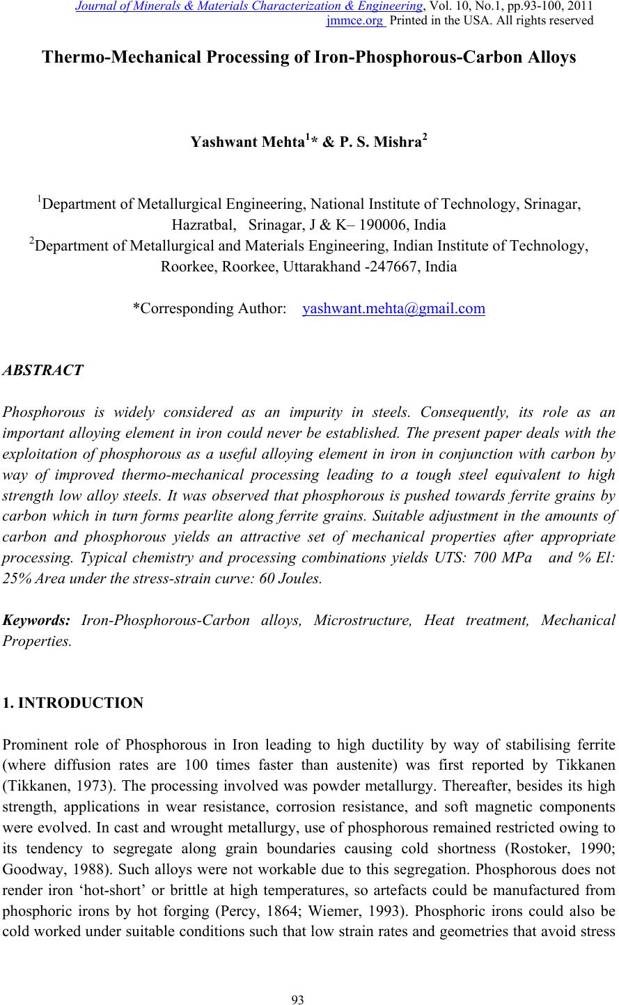 Journal of Minerals & Materials Characterization & Engineering, Vol. 10, No.1, pp.93-100, 2011 jmmce.org Printed in the USA. All rights reserved 93 Thermo-Mechanical Processing of Iron-Phosphorous-Carbon Alloys Yashwant Mehta1* & P. S. Mishra2 1Department of Metallurgical Engineering, National Institute of Technology, Srinagar, Hazratbal, Srinagar, J & K– 190006, India 2Department of Metallurgical and Materials Engineering, Indian Institute of Technology, Roorkee, Roorkee, Uttarakhand -247667, India *Corresponding Author: yashwant.mehta@gmail.com ABSTRACT Phosphorous is widely considered as an impurity in steels. Consequently, its role as an important alloying element in iron could never be established. The present paper deals with the exploitation of phosphorous as a useful alloying element in iron in conjunction with carbon by way of improved thermo-mechanical processing leading to a tough steel equivalent to high strength low alloy steels. It was observed that phosphorous is pushed towards ferrite grains by carbon which in turn forms pearlite along ferrite grains. Suitable adjustment in the amounts of carbon and phosphorous yields an attractive set of mechanical properties after appropriate processing. Typical chemistry and processing combinations yields UTS: 700 MPa and % El: 25% Area under the stress-strain curve: 60 Joules. Keywords: Iron-Phosphorous-Carbon alloys, Microstructure, Heat treatment, Mechanical Properties. 1. INTRODUCTION Prominent role of Phosphorous in Iron leading to high ductility by way of stabilising ferrite (where diffusion rates are 100 times faster than austenite) was first reported by Tikkanen (Tikkanen, 1973). The processing involved was powder metallurgy. Thereafter, besides its high strength, applications in wear resistance, corrosion resistance, and soft magnetic components were evolved. In cast and wrought metallurgy, use of phosphorous remained restricted owing to its tendency to segregate along grain boundaries causing cold shortness (Rostoker, 1990; Goodway, 1988). Such alloys were not workable due to this segregation. Phosphorous does not render iron ‘hot-short’ or brittle at high temperatures, so artefacts could be manufactured from phosphoric irons by hot forging (Percy, 1864; Wiemer, 1993). Phosphoric irons could also be cold worked under suitable conditions such that low strain rates and geometries that avoid stress 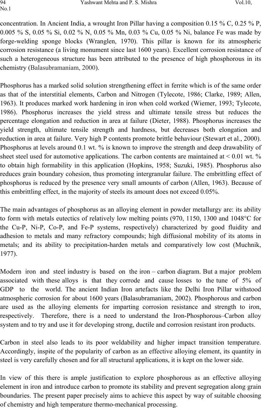 94 Yashwant Mehta and P. S. Mishra Vol.10, No.1 concentration. In Ancient India, a wrought Iron Pillar having a composition 0.15 % C, 0.25 % P, 0.005 % S, 0.05 % Si, 0.02 % N, 0.05 % Mn, 0.03 % Cu, 0.05 % Ni, balance Fe was made by forge-welding sponge blocks (Wranglen, 1970). This pillar is known for its atmospheric corrosion resistance (a living monument since last 1600 years). Excellent corrosion resistance of such a heterogeneous structure has been attributed to the presence of high phosphorous in its chemistry (Balasubramaniam, 2000). Phosphorus has a marked solid solution strengthening effect in ferrite which is of the same order as that of the interstitial elements, Carbon and Nitrogen (Tylecote, 1986; Clarke, 1989; Allen, 1963). It produces marked work hardening in iron when cold worked (Wiemer, 1993; Tylecote, 1986). Phosphorus increases the yield stress and ultimate tensile stress but reduces the percentage elongation and reduction in area at failure (Dieter, 1988). Phosphorus increases the yield strength, ultimate tensile strength and hardness, but decreases both elongation and reduction in area at failure. Very high P contents promote brittle behaviour (Stewart et al., 2000). Phosphorus at levels around 0.1 wt. % is known to improve the strength and deep drawability of sheet steel used for automotive applications. The carbon contents are maintained at < 0.01 wt. % to obtain high formability in this application (Hopkins, 1958; Suzuki, 1985). Phosphorus also reduces grain boundary cohesion, thus promoting intergranular failure. The embrittling effect of phosphorus is reduced by the presence very small amounts of carbon (Allen, 1963). Because of this embrittling effect, in the majority of steels its amount does not exceed 0.05%. The main advantages of phosphorus as an alloying element in powder metallurgy are: its ability to form with metals eutectics of relatively low melting points (970, 1150, 1300 and 1048°C for the Cu-P, Ni-P, Co-P, and Fe-P systems, respectively) characterized by good fluidity and adhesion to metals and many refractory compounds; high diffusional mobility of its atoms in metals; and its ability to precipitation-harden metals and comparatively low cost (Muchnik, 1977). Modern iron and steel industry is based on the iron – carbon diagram. But a major problem associated with these alloys is that they corrode and cause losses to the tune of 5% of GDP to the world. The ancient Indian Iron artefacts like the Delhi Iron Pillar withstood atmospheric corrosion for about 1600 years (Balasubramaniam, 2002). Phosphorous and carbon are used as the alloying elements for imparting corrosion resistance and strength to iron, respectively. Therefore, there is a need to understand the Iron-Phosphorous–Carbon alloy system and to try and use it for developing strong, ductile and corrosion resistant iron products. Carbon in steel also leads to its poor weldability and higher impact transition temperature. Accordingly, inspite of the popularity of carbon as an effective alloying element, its quantity in steel is very carefully chosen and for all structural applications, it is kept on the lower side. In view of this there is ample justification to explore phosphorous as an effective alloying element in iron and introduce carbon to promote its stability and prevent segregation along grain boundaries. The present paper precisely aims to achieve this aspect by way of suitable choosing of chemistry and high temperature thermo-mechanical processing. 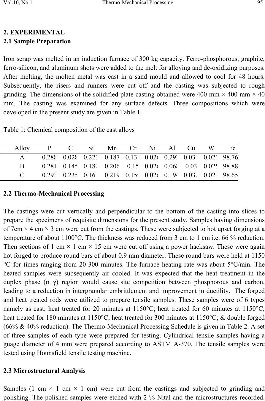 Vol.10, No.1 Thermo-Mechanical Processing 95 2. EXPERIMENTAL 2.1 Sample Preparation Iron scrap was melted in an induction furnace of 300 kg capacity. Ferro-phosphorous, graphite, ferro-silicon, and aluminum shots were added to the melt for alloying and de-oxidizing purposes. After melting, the molten metal was cast in a sand mould and allowed to cool for 48 hours. Subsequently, the risers and runners were cut off and the casting was subjected to rough grinding. The dimensions of the solidified plate casting obtained were 400 mm × 400 mm × 40 mm. The casting was examined for any surface defects. Three compositions which were developed in the present study are given in Table 1. Table 1: Chemical composition of the cast alloys Alloy P C Si Mn Cr Ni Al Cu W Fe A 0.28 8 0.02 8 0.22 1 0.18 7 0.13 8 0.02 6 0.29 2 0.03 1 0.02 7 98.76 2 B 0.28 1 0.14 5 0.18 2 0.20 6 0.1 5 0.02 6 0.06 8 0.0 3 0.02 5 98.88 C 0.29 3 0.23 5 0.16 1 0.21 9 0.15 9 0.02 6 0.19 4 0.03 2 0.02 3 98.65 2.2 Thermo-Mechanical Processing The castings were cut vertically and perpendicular to the bottom of the casting into slices to prepare the specimens of requisite dimensions for the present study. Samples having dimensions of 7cm × 4 cm × 3 cm were cut from the castings. These were subjected to hot upset forging at a temperature of about 1100°C. The thickness was reduced from 3 cm to 1 cm i.e. 66 % reduction. Then sections of 1 cm × 1 cm × 15 cm were cut off using a power hacksaw. These were again hot forged to produce round bars of about 0.9 mm diameter. These round bars were held at 1150 °C for times ranging from 20-300 minutes. The furnace heating rate was about 5°C/min. The heated samples were subsequently air cooled. It was expected that the heat treatment in the duplex phase (α+γ) region would cause site competition between phosphorous and carbon, leading to a reduction in intergranular embrittlement and improvement in ductility. The forged and heat treated rods were utilized to prepare tensile samples. These samples were of 6 types namely as cast; heat treated for 20 minutes at 1150°C; heat treated for 60 minutes at 1150°C; heat treated for 180 minutes at 1150°C; heat treated for 300 minutes at 1150°C; & double forged (66% & 40% reduction). The Thermo-Mechanical Processing Schedule is given in Table 2. A set of three samples of each type were prepared for testing. Cylindrical tensile samples having a guage diameter of 4 mm were prepared according to ASTM A-370. The tensile samples were tested using Hounsfield tensile testing machine. 2.3 Microstructural Analysis Samples (1 cm × 1 cm × 1 cm) were cut from the castings and subjected to grinding and polishing. The polished samples were etched with 2 % Nital and the microstructures recorded. 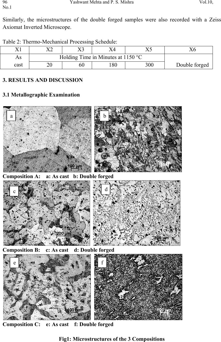 96 Yashwant Mehta and P. S. Mishra Vol.10, No.1 Similarly, the microstructures of the double forged samples were also recorded with a Zeiss Axiomat Inverted Microscope. Table 2: Thermo-Mechanical Processing Schedule: X1 X2 X3 X4 X5 X6 As cast Holding Time in Minutes at 1150 °C Double forged 20 60 180 300 3. RESULTS AND DISCUSSION 3.1 Metallographic Examination Composition A: a: As cast b: Double forged Composition B: c: As cast d: Double forged Composition C: e: As cast f: Double forged Fig1: Microstructures of the 3 Compositions a b c d e f  Vol.10, No.1 Thermo-Mechanical Processing 97 The cast structure of composition A showed large sized ferrite grains (Fig. 1). The cast structure of composition B showed ferrite grains and pearlite grains which were smaller than those of composition A. the cast structure of composition 3 showed dendrites of ferrite and pearlite grains. The microstructures of the double forged samples showed fine untransformed ferrite grains and ferrite grains formed after transformation of austenite grains. 3.2 Mechanical Properties The mechanical properties of the alloys prepared in this study are shown in Table 1. Table 1: Mechanical properties of Fe-0.3P- xC alloys Composition Specimen Conditio n (Processing) Proof / Yield Stress (MPa) Ultimate Te nsile Stress (MPa) Elong ati on (%) A X1 330.86 350.99 4.49 X2 392.52 536.71 18.05 X3 406.21 559.96 22.48 X4 384.38 530.56 25.03 X5 365.27 515.97 26.55 X6 468.53 593.63 24.83 B X1 339.76 495.97 9.5 2 X2 423.63 619.71 24.55 X3 413.95 630.44 25.20 X4 415.91 624.58 23.07 X5 409.65 604.10 20.76 X6 471.08 618.30 24.07 C X1 357.39 432.21 4.93 X2 446.27 673.05 17.79 X3 431.17 663.69 19.53 X4 483.17 688.36 18.84 X5 425.17 636.46 21.37 X6 519.98 706.07 24.84  98 Yashwant Mehta and P. S. Mishra Vol.10, No.1 X1 X2 X3 X4 X5 X6 320 340 360 380 400 420 440 460 480 500 520 540 A B C Proof Stress (MPa) Specimen Condition (Processing) Fig 2: The variation of proof stress with respect to specimen condition. As expected, the proof stress increased with the increase in the percentage of carbon in the compositions (Figure 2). The double forged specimen displayed the maximum proof stress as compared to the as cast and heat treated samples since it had the finest grain structure. The heat treated samples did not show any general trend with respect to the proof stress values. The stress values decreased after about 20 minutes of holding time at 1150 °C for the B and C compositions. X1 X2 X3 X4 X5 X6 300 350 400 450 500 550 600 650 700 750 A B C Ultimate tensile Stress (MPa) Specimen Condition (Processing) Fig 3: The variation of ultimate tensile stress with respect to specimen condition.  Vol.10, No.1 Thermo-Mechanical Processing 99 The ultimate tensile stress showed a rising trend for all the specimen conditions with a rise in the carbon content, as was expected (Figure 3). No general trend could be observed in the stress values displayed by the heat treated compositions. The double forged specimen showed the maximum stress value for each composition due to its fine grained structure. The UTS values of the B & C compositions showed a decreasing trend beyond 20 minutes of heating at 1150 °C. The UTS values of the double forged samples are nearly twice that of the as cast values. X1 X2 X3 X4 X5 X6 0 5 10 15 20 25 30 A B C Elongation (%) Sp e c ime n Con d itio n (Pro c e ssin g ) Fig 4: The variation of percentage elongation with respect to specimen condition. The percentage elongation of the double forged specimen was nearly four to five times that displayed by the as cast samples (Figure 4). The elongation values did not show any general trend in the heat treated category. The elongation values improved with an increase in holding time for the A and C compositions. The elongation of the B composition decreased after 60 minutes of heating at 1150 °C. The elongation of the cast samples of the B composition showed 9.5 % elongation which is significant. The double forged specimens of all the three compositions showed the best ductility values. 4. CONCLUSIO NS a. The UTS values increased with the increase in the carbon content irrespective of the thermo-mechanical processing schedule. b. The proof stress values increased with the increase in the carbon content irrespective of the thermo-mechanical processing schedule.  100 Yashwant Mehta and P. S. Mishra Vol.10, No.1 c. The %age elongation values improved with an increase in holding time for A & C compositions. d. The double forged specimens showed the best combination of strength and ductility. e. All the 3 compositions show better strength in the thermo mechanically processed condition as compared to mild steel. ACKNOWLEDGEMENT The authors are thankful to Shri Ajay Aggarwal Owner of Vaishnav Steel Private Limited, Muzaffernagar for providing the castings of the Fe-0.3P-xC alloys for research purposes. We are also thankful to Prof. K Chandra for his support in this endeavour. REFERENCES Allen N. P. in ‘Iron and its dilute solid solutions’, 1963, New York, Willey Interscience 271-308. Balasubramaniam, R., Corros. Sci., 2000 42 2103–2129. Balasubramaniam R 2002 Delhi iron pillar—New insights (Shimla: Indian Institute of Advanced Study) Clarke B. D. and McIvor I. D., Ironmaking & Steelmaking, 1989, 16, 335-344. Dieter G. E.,’ Mechanical Metallurgy’, 3 rd edn, 1988, London, McGraw-Hill. Goodway M. and Fisher R.M., Hist. Metall., 1988, 22, 21-23 Hopkins B E and Tipler H R 1958 J. Iron Steel Inst. 188, 218 Muchnik S. V., Phosphorus-containing alloys, in: Encyclopedia of Inorganic Materials [in Russian], Vol. 2, USE, Kiev 1977, 666-667. Percy J., ‘Metallurgy- iron and steel’, 1864, London, John Murray. Rostoker W. and Bronson B., ‘Pre industrial iron-its technology and ethnology’, Archaeomaterials Monograph No.1, 1990, Philadelphia, PA, University of Pennsylvania. Stewart J W, Charles J A and Wallach E R 2000 Mater. Sci. Technol. 16, 275 Suzuki S, Obata M, Abiko K and Kimura H 1985 Trans. ISIJ 25, 62 Tikkanen M.H., ‘The application of sintering theory in practice,’ Physics of sintering- Theory and Practice, Edited by M.M.Risti.., 1973, 441-453. Tylecote R. E., ‘The prehistory of metallurgy in the British Isles’, 1986, London, the Institute of Metals. Wiemer K. ‘Early British iron edged tools- a metallurgical survey’ Ph D thesis, University of Cambridge, 1993 Wranglen G Corrosion Science, 1970, 10, 761- 770. |