Paper Menu >>
Journal Menu >>
 Journal of Minerals & Materials Characterization & Engineering, Vol. 9, No.9, pp.775-786, 2010 jmmce.org Printed in the USA. All rights reserved 775 Oxidation Behavior of Fe3Al-5Cr- (0, 0.5, 1.5) Ti Alloys at Temperature Ranges from 800oC to 1200 oC Hossam Halfa Researcher, Steel Technology Department, Central Metallurgical R&D Institute (CMRDI), P. O. Box 87 Helwan, Egypt, hossamhalfa@cmrdi.sci.eg; http://www.cmrdi.sci.eg ABSTRACT As cast Fe3Al-5Cr- (0, 0.5, 1.5) Ti alloys were isothermally oxidized at temperature ranges from 800 to 1200 0C in air, and their oxidation characteristics were studied using thermogravimetric analyzer, X-ray diffractometer, optical microscope and scanning electron microscope. It was found that Ti increased the oxidation resistance of Fe3Al- Cr alloys to a certain extent. The oxide scales that formed on the unalloyed Fe3Al alloys consisted primarily of α-Al2O3 containing a small percentage of dissolved iron and chromium ions. The experimental result of unalloyed Fe3Al alloy shows also, an Al-free, Fe-enriched zone was formed beneath the oxide scale, owing to Al consumption to form the oxide scale. The oxide scale on unalloyed Fe3Al alloy had poor adherence. On the other hand, the result shows that, the oxidation rate decreased for titanium alloyed Fe3Al alloy, which has been explained by a change in the nature of the surface scale. Analysis of the oxidation product revealed that the presence of titanium as alloying elements change the nature of formed oxide scale and protect the bulk alloy from further oxidation. Keywords: Intermetallic, compound, Fe3Al, scale, oxidation resistance, High temperature 1. INTRODUCTION Development of iron aluminides, based on Fe3Al, for applications in high temperature environments is an important area of research, as these materials possess unique properties such as, high strength to weight ratio, good wear resistance, good cavitation resistance, excellent oxidation and sulfidation resistance [1–14]. Iron aluminides are well known to have good oxidation and sulfidation resistance due to the formation of an external, protective alumina scale [15–19], which is more stable under these environmental conditions. In addition to these, they cost relatively less than stainless steels and also by application of these alloys it would be possible to avoid the use of strategic elements like Ni. Due to these added  776 Hossam Halfa Vol.9, No.9 advantages these materials are considered as potential candidates for the replacement of stainless steel. The major limitations of these intermetallics are however poor ductility at ambient temperatures and a decrease in strength above 600 oC [10-14]. These mechanical properties can be improved most efficiently by controlling the microstructure and adding suitable alloying element especially Cr, Ti, V. Therefore, it is of increasing interest to study the high temperature oxidation of the new and developed Fe3Al-CrTiV alloys. The oxidation property is an important factor for successful utilization of these materials. Chromium apparently accelerated the initial growth of Al2O3, so that rapid weight gains occurred during initial oxidation [20-22]. In preceding paper we will study the oxidation behavior of Fe3Al-5Cr- (0, 0.5, 1.5) Ti alloys at temperature ranges from 800 to 1200 0C. 2. EXPERIMENTAL WORK 2.1 Melting and Casting To study the effect of titanium as alloying element, three alloying chemical composition range from 0 wt% titanium to 1.3 wt% were titanium investigated. Five kilograms of each of the Fe3Al alloys were melted from pure elements in a skull induction-melting furnace (ISM), which employed a water-cooled copper crucible. High purity argon was used as an inert gas, and titanium getters were melted to minimize interstitial gases including oxygen and nitrogen from the furnace atmosphere before melting. Different component of the alloy were arranged by special manner as shown in Figure 1. The alloying elements (chromium, titanium and vanadium) were loaded between the two parts of iron melt stock. New and developed batch of Fe3Al alloying elements was loaded into the skull induction melting furnace crucible under vacuum with pressure 1*10-3 mbar. Different component of the alloy were arranged by special manner as shown in Figure 1. The entire crucible was inductively heated noting the power (based on voltage, current, and time at each setting) required for melting. The aluminum melt stock was melted slowly to the iron melt stock, number (1) exothermic reaction will be done after determining that the entire iron melt stock number (2) was molten. The exothermic reaction between iron and aluminum in upper part of the crucible resulted in a sudden increase in temperature recorded by well calibrated pyrometer. The temperature rose steadily as melting and reaction of the product of exothermic reaction in upper part continued with the iron stock in the lower part of the furnace. This was accompanied by extreme brightness with white radiation, and a vapor cloud escaped from the crucible for several minutes. Oxidation of aluminum resulted in a reduction of oxides may be contained in the charge material (iron, ferrochrome, titanium turns) and part of the temperature rise may be attributed to the oxidation of aluminum. The skull induction melting ingot was melted six times, inverting the ingot after each melting to ensure homogeneity. Cylindrical samples were obtained by drop casting into a Cu-mould of diameter 20 mm. 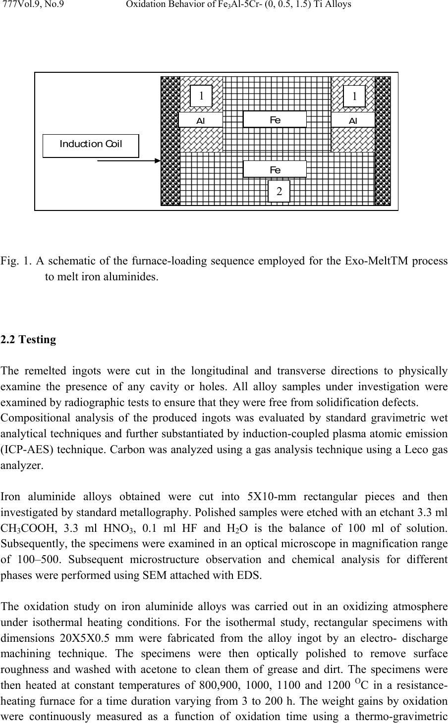 Vol.9, No.9 Oxidation Behavior of Fe3Al-5Cr- (0, 0.5, 1.5) Ti Alloys 777 Fig. 1. A schematic of the furnace-loading sequence employed for the Exo-MeltTM process to melt iron aluminides. 2.2 Testing The remelted ingots were cut in the longitudinal and transverse directions to physically examine the presence of any cavity or holes. All alloy samples under investigation were examined by radiographic tests to ensure that they were free from solidification defects. Compositional analysis of the produced ingots was evaluated by standard gravimetric wet analytical techniques and further substantiated by induction-coupled plasma atomic emission (ICP-AES) technique. Carbon was analyzed using a gas analysis technique using a Leco gas analyzer. Iron aluminide alloys obtained were cut into 5X10-mm rectangular pieces and then investigated by standard metallography. Polished samples were etched with an etchant 3.3 ml CH3COOH, 3.3 ml HNO3, 0.1 ml HF and H2O is the balance of 100 ml of solution. Subsequently, the specimens were examined in an optical microscope in magnification range of 100–500. Subsequent microstructure observation and chemical analysis for different phases were performed using SEM attached with EDS. The oxidation study on iron aluminide alloys was carried out in an oxidizing atmosphere under isothermal heating conditions. For the isothermal study, rectangular specimens with dimensions 20X5X0.5 mm were fabricated from the alloy ingot by an electro- discharge machining technique. The specimens were then optically polished to remove surface roughness and washed with acetone to clean them of grease and dirt. The specimens were then heated at constant temperatures of 800,900, 1000, 1100 and 1200 OC in a resistance- heating furnace for a time duration varying from 3 to 200 h. The weight gains by oxidation were continuously measured as a function of oxidation time using a thermo-gravimetric 2 Al Fe Al Fe Induc tio n Coil 2 1 1  778 Hossam Halfa Vol.9, No.9 analyzer. Because of a high degree of scattering relative to the quite small weight gains [21], duplicate runs were carried out to assure the reproducibility of data. Identification of different phases present in the produced in the produced ingots of alloy samples and oxide layers was carried out by X-ray diffraction (XRD) using Cu Ka radiation (λ = 0.154 nm) with a nickel filter and a secondary beam monochromator. One gram of each alloy sample taken in powder form was scanned from 20o to 110o at a scanning rate of 2o /min. The measured ‘d’ values with their corresponding intensities were compared with the data reported in the standard ASTM card index for the identification of the desired phases. 3. RESULT & DISCUSSION 3.1 Alloy Melting and Casting The ingots weighing 5 kg were produced by top pouring using water cooled copper mold. They had a satisfying surface appearance and no crack was detected. Table 1 lists their chemical compositions determined by conventional chemical analysis and induction-coupled plasma atomic emission (ICP-AES) technique. Both titanium free and titanium containing Fe3Al alloys are also presented for comparison. The aluminum compositions at different sections, including the upper, center and bottom of ingot, were measured. By vacuum induction melting, the compositions of Fe3Al-based alloys can be well controlled for complex (Fe3Al–CrTiV) alloys. The aluminum composition has an acceptable difference level at different sections of the ingot. The levels of phosphorus and sulfur impurity were found to be low. Table 1. Compositions of 5 Kg - ingot Fe3Al-based alloys prepared by vacuum induction melting and top cast. Chemical composition Alloy No. Alloy Designation C Al S P Ti V Cr Mn Fe 1 Fe3Al 0.5 Top 13.55 Center 13.61 Bottom 13.45 0.0 77 <0.0020 0.04 5 5.8 5 0.19 1 Balance 2 Fe3Al(0.5Ti) 0.5 Top 13.45 Center 13.43 Bottom 13.41 0.0 71 <0.0020.5 0.03 5 5.9 0 0.18 1 Balance 3 Fe3Al(1.3Ti) 0.5 Top 13.62 Center 13.7 Bottom 13.55 0.0 79 <0.0021.3 0.03 5 5.9 4 0.19 1 Balance 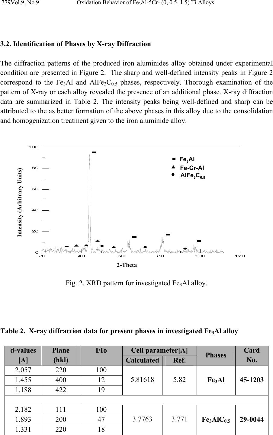 Vol.9, No.9 Oxidation Behavior of Fe3Al-5Cr- (0, 0.5, 1.5) Ti Alloys 779 3.2. Identification of Phases by X-ray Diffraction The diffraction patterns of the produced iron aluminides alloy obtained under experimental condition are presented in Figure 2. The sharp and well-defined intensity peaks in Figure 2 correspond to the Fe3Al and AlFe3C0.5 phases, respectively. Thorough examination of the pattern of X-ray or each alloy revealed the presence of an additional phase. X-ray diffraction data are summarized in Table 2. The intensity peaks being well-defined and sharp can be attributed to the as better formation of the above phases in this alloy due to the consolidation and homogenization treatment given to the iron aluminide alloy. 20 40 60 80100120 0 20 40 60 80 100 Fig. 2. XRD pattern for investigated Fe3Al alloy. Table 2. X-ray diffraction data for present phases in investigated Fe3Al alloy Cell parameter[A] d-values [A] Plane (hkl) I/Io Calculated Ref. Phases Card No. 2.057 220 100 1.455 400 12 1.188 422 19 5.81618 5.82 Fe3Al 45-1203 2.182 111 100 1.893 200 47 1.331 220 18 3.7763 3.771 Fe3AlC0.5 29-0044 Fe 3 A l Fe-Cr-Al AlFe 3 C 0.5 Intensity (Arbitrary Units) 2-Theta  780 Hossam Halfa Vol.9, No.9 3.3 Microstructure Effect of titanium on additional phases presence on Fe3Al alloys under investigation was discussed by means of optical microscope and scanning electron microscope equipped with EDS unit. All as-cast alloys have been examined by light optical microscopy as well as by scanning electron microscope and some typical microstructures of each group of alloys are shown in Figure 3. This figure shows that the structure of alloys under investigation consists of ordered Fe3Al. Thorough examination of the specimen revealed the presence of an additional unknown phase. Arrowheads in Figure 3-a and 3-b mark the particles of this phase. This figure also show that, a uniform distribution of coarse particles, in the form of slightly elongated blocky particles and needle particles, see Fig. 3, spread throughout the grains and lining the grain boundaries. The EDS analysis has shown that the composition of this phase is approximately Al–9 wt% Cr–20 wt% Fe is the balance. (3a) Fe3Al-0Ti Fe3Al-0.5 Ti Fe3Al-1.3Ti (3-b) Fig. 3. Show metallographic examination of investigated Fe3Al alloys by a) light optical microscopy b) scanning electron microscope accompanying with the analysis of unknown phase present in such alloys. 3.4. Oxidation Study on Iron Aluminide Alloys An evaluation of the oxidation resistance of iron aluminide alloys was carried out under isothermal heating conditions by monitoring their change in weight with time. Plots showing pattern of the above alloys are shown in Figures 4 and 5. Oxidation kinetics data (figure 4 and 5) shows the Ti free alloy to be oxidizing at a considerably greater rate than Ti-containing Al 9.2 % Cr 20.6 % Fe 70.2 % Al 8.7 % Cr 19.4 % Fe 71.9 %  Vol.9, No.9 Oxidation Behavior of Fe3Al-5Cr- (0, 0.5, 1.5) Ti Alloys 781 alloys. After 200 hr oxidation, weight gain of Ti free alloy (alloy No. 1) was found to be nearly five times greater than that of the Ti-containing alloys (alloy No. 2 and alloy No.3). 0 5E-09 1E-08 1.5E-08 2E-08 2.5E-08 050100 150 200 Wt Gain , Mg2/Cm 4 time, hr Fe3Al-0 Ti Fe3Al-0 .5 Ti Fe3Al-1.3 Ti 800 0.E+00 5.E-08 1.E-07 2.E-07 2.E-07 3.E-07 3.E-07 050100 150 200 wt gain , mg2/cm 4 time, hr Fe3Al -0 Ti Fe3Al -0.5 Ti Fe3Al -1.3 Ti 1000 Fig. 4. Squares of the mass gain as a function of oxidation time for investigated iron aluminides alloy at (a) 800 °C, (b) 1000 °C during 200 hours.  782 Hossam Halfa Vol.9, No.9 0.E+00 2.E-06 4.E-06 6.E-06 8.E-06 1.E-05 1.E-05 050100 150 200 wt gain , mg2/cm 4 time, hr Fe3Al -0 Ti Fe3Al -0.5 Ti Fe3 A l -1.3 Ti 1100 0.E+00 5.E-04 1.E-03 2.E-03 2.E-03 3.E-03 050100 150 200 250 wt gain , mg2/cm4 Time, hr Fe3Al -0 Ti Fe3Al -0.5 Ti Fe3Al -1.3 Ti 1200 Fig. 5. Squares of the mass gain as a function of oxidation time for investigated iron aluminides at (a) 1100 °C, (b) 1200 °C during 200 hours. Figure 6 shows a cross-sectional image of the oxide scale formed on alloys under investigation Fe3Al-CrTiV after oxidation at 1100 oC for 200 hr. In the case of Fe3Al with low titanium content, the cross-sectional image reveals the non-adherent, fragile oxide scales. The oxide scale spalled not only during oxidation testing but also during sample handling at room temperature. From the initial oxidation stage, the scales were susceptible to spallation. After spalling, another healing oxide layer, which was also non-adherent, formed. It is known that the scale detachment is assisted by the formation of voids or cavities that form owing to the coalescence of vacancies induced by the uneven flux of anions and cations around the  Vol.9, No.9 Oxidation Behavior of Fe3Al-5Cr- (0, 0.5, 1.5) Ti Alloys 783 scale matrix interface [23]. In the other case, for Fe3Al high titanium content, Spallation of the formed scale was not observed for the investigated alloys. Fe3Al blank Top Bottom Fig. 6. Optical microscope image of the oxide scale formed on Fe3Al-CrTiV after oxidation at 1100 oC for 200 h. On the other hand, presence of second phase has a great effect on oxidization resistance of investigated alloys. By using the metallographic photos of the alloy (before and after oxidation test) and EDS of the second phase simultaneously with the kinetic data of oxidation we found that, by increase percentages of second phase with chemical composition (approximately Al–9 wt% Cr–20 wt% Fe is the balance) oxidation resistance increase. The previous result was confirmed by many investigators [24, 25]. Sadique et al[23] and Liu et al[24] concluded that , the oxidation resistance of Fe-Cr-A1 alloy, at 20wt% Cr or greater, 5wt% A1 is usually attributed to the formation of protective, dense and adherent oxides. In order to investigate the reason for the considerable difference in oxidation rates and oxidation behavior (figures (4-5) of the investigated alloys, oxide scales were characterized. The result of XRD (Fig.(7)) revealed that the formed oxide region was mainly composed of Fe3AlC0.5, titanium oxide (TiO2) and aluminide also existed in the region. In addition, The XRD shown in Figure 7 indicates that Fe and Cr ions from the matrix penetrated into the α- Al2O3 oxide scale. These ions are known to accelerate the transformation of θ- to α- Al2O3, because the transient formation of hexagonal Fe2O3 and Cr2O3 favors the nucleation of α- Al2O3 [26-28]. This may be the main reason for the absence of any θ - Al2O3 in the oxide scales formed on Fe3Al-CrTiV alloys, as shown in Figure 7. So, we can concluded that, titanium as alloying elements has a positive potential on increasing the oxidation resistance of the investigated alloys through increase the volume fraction of second phase and share as titanium oxide on the formed scale. The XRD resultant can be interpretation as follows: during the heating process, Al in the surface were oxidizes at the same time, the consumption of aluminum promotes the moving of Ti, Cr and Fe atoms in the outwards direction because it increases the crystal lattice aberrance and vacant. During the process, parts of the pores go out of the oxidation product 1 2 3 1 2 3 1 2 3  784 Hossam Halfa Vol.9, No.9 layer. The decrease and closure of pores in the oxidation product (region A) is beneficial to the oxidation resistance, for it lowers the oxygen entrance. It also appear from the XRD, for alloy No.3, that high titanium content restrict the moving of Cr and Fe and decrease its content in oxide layer which lead to lower pores in the oxidation product region and protect the matrix from further oxidation. In other words, the titanium content in these alloys is high enough to ensure the production of an oxide layer composed of pure alumina (free from Cr2O3 and Fe2O3), which is a slow-growing phase. 20 40 60 8030 50 70 0 400 800 1200 1600 0 400 800 1200 1600 0 400 800 1200 1600 Fe 3 Al 5Cr-1.5Ti Fe 3 Al 5Cr-0.5Ti 2 - T h e t a - S c a l e L i n ( C o u n t s ) Al 2 O 3 Al 1.98 Cr .08 O 3 Fe 3 Al TiO 2 Fe 3 AlC 0.5 Fe 3 Al 5Cr-0Ti Fig. 7. XRD pattern of the oxidation product after 200-hour exposure at 1100 OC in air for investigated Fe3Al.  Vol.9, No.9 Oxidation Behavior of Fe3Al-5Cr- (0, 0.5, 1.5) Ti Alloys 785 4. CONCLUSIONS From the preceding results, it can be concluded that 1. The produced alloy has exhibited a homogenized composition, refined microstructure, and high hardness with adequate oxidation resistance suitable for high temperature application. 2. Titanium as alloying elements has a positive potential on increasing the oxidation resistance of the investigated alloys through increase the volume fraction of second phase and share as titanium oxide on the formed scale. 3. The oxidation rate decreased in the order of Fe3Al5Cr-0Ti, Fe3Al6Cr-0.5Ti and Fe3Al5Cr-1.5Ti. The oxide scales that formed on Fe3AlCr-0Ti alloy consisted primarily of α- Al2O3 containing a small percentage of Fe and less than 1% of Cr. They were non-adherent and fragile. 4. In the case of Ti containing alloys, the result of XRD revealed that the formed oxide region was mainly composed of Fe3AlC0.5, titanium oxide (TiO2) and aluminide also existed in the region. 5. In the case of Ti containing alloys, although there is some Al1.98Cr0.08O3, at the surface layer there is no obvious sign of crack or other fault found on the surface layer, which proves that the formed surface layer can prevent the substrate from rapid degradation in oxygen-containing atmospheres. REFERENCES 1. W.J. Quadakkers, D. Naumenko, and E. Wessel, Oxidation of Metals 61(l/2), 17, 2004. 2. H. Al-Badairy and G.J. Tatlock, Oxidation bf Metals 53(1/2), 157, 2000. 3. I.G. Wright, R. Peraldi, and B.A. Bint, Materials Science Forum 4 6 1 -464, 579, 2004. 4. S.J. Taniguchi and A. Andoh, Oxidation of Metals52 (1/2), 1, 1999. 6. N.S. Stoloff, Int. Met. Rev. 29, 123, 1984. 7. C.G. McKamey, J.H. DeVan, P.F. Tortorelli, V.K. Sikka, J. Mater.Res. 6, 1779, 1991. 8. S.C. Deevi, V.K. Sikka, Intermetallics 4, 357, 1996. 9. C.T. Liu, J.O. Stiegler, F.H. Froes, Ordered intermetallics, 10th ed., Metals Handbook, vol. 2, ASM, Metals Park, USA, 913, 1990. 10. C.T. Liu, K.S. Kumar, Ordered intermetallic alloys, part 1, nickel and iron aluminides, J. Metals 45, 38 1993. 11. C.T. Liu, J.O. Stiegler, F.H. Froes, Ordered intermetallics, 10th ed., Metals Handbook, vol. 2, ASM, Metals Park, USA, 913, 1990. 12. W.J. Quadakkers, D. Naumenko, and E. Wessel, Oxidation of Metals 61(l/2), 17, 2004. 13. H. Al-Badairy and G.J. Tatlock, Oxidation of Metals 53(1/2), 157, 2000. 14. I.G. Wright, R. Peraldi, and B.A. Bint, Materials Science Forum 461-464, 579, (2004). 15. S.J. Taniguchi and A. Andoh, Oxidation of Metals52(1/2), 1, 1999. 16. P.F. Tortorelli, J.H. DeVan, Mater. Sci. Eng., A Struct. Mater.: Prop. Microstruct. Process. 153, 573 ,1992.  786 Hossam Halfa Vol.9, No.9 17. S.W. Banovic, J.N. DuPont, A.R. Marder, Oxid. Met. 54, 339, 2000. 18. P.F. Tortorelli, K. Natesan, Mater. Sci. Eng., A Struct. Mater.: Prop. Microstruct. Process. 258, 115 ,1998. 19. K. Natesan, Mater. Sci. Eng., A Struct. Mater.: Prop. Microstruct. Process. 258, 126, 1998. 20. B.A. Pint, P.F. Tortorelli, I.G. Wright, Mater. High Temp. 16, 1, 1999. 21. J.H. DeVan, in: T. Grobstein, J. Doychak (Eds.), Oxidation of High-Temperature Intermetallics, TMS, Warrendale, PA, 107, 1989. 22. P.F. Tortorelli, J.H. DeVan, in: J.H. Schneibel, M.A. Crimp (Eds.), Processing, Properties and Application of Iron Aluminides, TMS, Warrendale, PA, 257, 1994. 23. P.F. Tortorelli, J.H. DeVan, Mater. Sci. Eng. A153, 573, 1992. 24. G.H. Meier, in: H.J. Grabke, M. Schu¨ tze (Eds.), Oxidation of Intermetallics, Wiley_/VCH, New York, 15, 1997. 25. S.E. Sadique, A.H. Mollah, and M.S. Islam, Oxidation of Metals 54(5/6), 385, 2000. 26. P.S. Liu, Rare Materials and Engineering 329, 681, 2003 (in Chinese). 27. G.C. Bye, G.T. Simpkin, J. Am. Ceram. Soc. 57, 367, 1974. 28. S.C. Choi, H.J. Cho, D.B. Lee, Oxid. Met. 46, 109, 1996. 29. B.A. Pint, J.R. Martin, L.W. Hobbs, Solid State Ionics 78, 99, 1995. |