Paper Menu >>
Journal Menu >>
 Journal of Minerals & Materials Characterization & Engineering, Vol. 9, No.8, pp.693-708, 2010 jmmce.org Printed in the USA. All rights reserved 693 Effects of Heat Treatment on the Mechanical Properties of Rolled Medium Carbon Steel O.O. Daramola, B.O. Adewuyi and I.O. Oladele Ajaokuta Steel Company Limited, Ajaokuta Steel City, Kogi State, Nigeria., and Metallurgical and Materials Engineering Department, Federal University of Technology, Akure, Ondo State, Nigeria Corresponding Author: Ojayth ompsoms@yahoo.com ABSTRACT Investigations were carried out to study the effects of heat treatment on the mechanical properties of rolled medium carbon steel. The steel was heated to the austenizing temperature of 8300C and water quenched; It was reheated to the ferrite – austenite two phase region at a temperature of 7450C below the effective Ac3 point. The steel was then rapidly quenched in water and tempered at 4800C to provide an alloy containing strong, tough, lath martensite (fibres) in a ductile soft ferrite matrix. The result shows that the steel developed has excellent combination of tensile strength, impact strength and ductility which is very attractive for structural use. Keywords: Lath martensite, Ferrite, Austenite, Tensile strength and Ductility. 1. INTRODUCTION Steel is an alloy of iron and carbon, where other elements are present in quantities too small to affect the properties. The other alloying elements allowed in plain-carbon steel are manganese (1.65% max) and silicon (0.60% max) [13]; Steel with low carbon content has the same properties as iron, soft but easily formed. As carbon content rises, the metal becomes harder and stronger but less ductile and more difficult to weld. Higher carbon content lowers steel melting point and its temperature resistance in general [18]. Rolled medium carbon steel products are produced through a forming process called rolling. The process is carried out in a rolling mill which consist of a complex machine for deforming metal in rotary rolls and performing auxiliary operations such as transportation of stock to rolls, disposal after rolling, cutting, cooling, piling  694 O.O. Daramola, B.O. Adewuyi and I.O. Oladele Vol.9, No.8 or coiling e-t-c. Carbon billets are charged into a reheating furnace with the aid of charging devices, the roller tables takes the billet to the reheating furnace one at a time, the billets are preheated and latter discharged and made to pass through the working group of stands where reduction is effected. Heat treatment involves the application of heat, to a material to obtain desired material properties (e.g. mechanical, corrosion. electrical, magnetic, e-t-c.). During the heat treatment process, the material usually undergoes phase microstructural and crystallographic changes [14]. The purpose of heat treating carbon steel is to change the mechanical properties of steel, usually ductility, hardness, yield strength tensile strength and impact resistance. The electrical, corrosion and thermal conductivity are also slightly altered during heat treatment process. The standard strengths of steels used in the structural design are prescribed from their yield strength. Most engineering calculations for structure are based on yield strength [11]. Recent urban building in Nigeria have become taller for more effective utilization of above ground space and have increased in size and complexity through the adoption of new structural design. These trends have led to demand for steel of greater strength, good ductility and toughness. The special objectives of the research work are to carry out heat treatment process on locally produced rolled medium carbon steel, evaluate the effect of heat treatment processes on the mechanical properties such as tensile strength, ductility, toughness and hardness of the rolled steel and determine high strength, high ductility and low yield ratio of the rolled medium carbon steel. 2. MATERIALS AND METHODS The material used in this study was 12mm diameter rolled medium carbon steel bars. Samples of the material were collected and prepared into tensile, impact, hardness and metallographic examination specimens. The spectrometric analysis of the steel was carried out to determine its chemical composition. The result is shown in Table 1. 2.1 Determination of operating Temperature. The lower critical temperature (AC1) and upper critical temperature (AC3) were determined by Grange empirical formula [9] as presented here AC1(0C) = (133 – 25Mn + 40si + 42Cr – 26Ni) – (32) 5/9----------------1.1 AC3(0C) = (1570 – 323C – 25Mm + 80si – 3Cr – 32Ni) – (32)5/9-------1.2 The carbon equivalent and estimate of austenite carbon in equilibrium are calculated from the chemical composition as given by [11] and [1] Ceq = %C + %Mn + (Cr+Mo+v ) + %(Ni+Cu)…… … ……1.3 6 5 15  Vol.9, No.8 Effects of Heat Treatment 695 Co = T - 0.17Si - 0.95………………………………….1.4 420 Where T = Austenite Temperature The results are presented in Table 1. Table 1: Chemical Composition of As- Roll e d M ed i u m C a rb o n S t e el . C Si Mn P S Cr Mo Ni Al Co 0.353 0.290 0.987 0.050 0.057 0.071 0.00500.110 0.025 0.015 Cu Nb Ti V W Pb Sn Zn Fe 0.185 0.0050 0.0037 0.0057 0.010 0.00500.026 0.007697.805 Table 2: Carbon equivalent (Ceq) and Estimate of Austenite Carbon in Equilibrium (Co) of the Steel. Ceq Co(7350C) Co(7450C) Co(8400C) 0.55 0.790 0.82 1.05 2.2 Heat Treatment Processes Representative samples of as-rolled medium carbon steel were subjected to heat treatment processes. 2.2.1 Quenching + Quenching + Lamelarizing + Temperin g (Q+Q+L+T). The steel specimens were heated to the austenizing temperature of 8300C, soaked for 20 minutes and quenched in water, this process was repeated again before the specimens were thereafter heated to the dual phase region at a temperature of 7450C, soaked for 20 minutes and quenched in water. The specimens were finally tempered at a temp er at ur e of 48 00C for 30 minutes. 2.2.2 Quenching, Lamelarizing and Temp ering (Q+L+T). The steel specimens were heated to 8300C, soaked for 20 minutes and quenched in water, the specimens were reheated to the dual phase region at a temperature of 7450C, soaked for 20 minutes and quenched in water. The specimens were tempered at temperature of 4800C for 30 minutes. 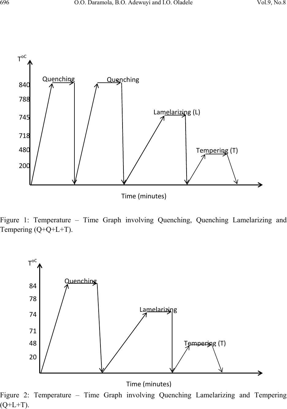 696 O.O. Daramola, B.O. Adewuyi and I.O. Oladele Vol.9, No.8 Figure 1: Temperature – Time Graph involving Quenching, Quenching Lamelarizing and Tempering (Q+Q+L+T). Figure 2: Temperature – Time Graph involving Quenching Lamelarizing and Tempering (Q+L+T). 200 480 718 745 788 840 ToC QuenchingQuenching Lamelarizing(L) Tempering(T) Time(minutes) 20 48 71 74 78 84 ToC Quenchin g Lamelarizin g Tem p erin g ( T ) Time ( minutes ) 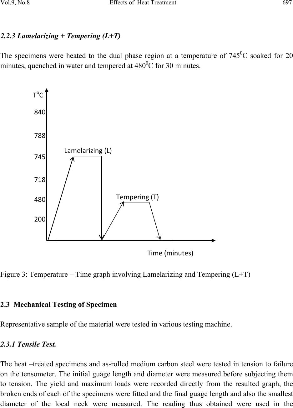 Vol.9, No.8 Effects of Heat Treatment 697 2.2.3 Lamelarizing + Tempering (L+T) The specimens were heated to the dual phase region at a temperature of 7450C soaked for 20 minutes, quenched in water and tempered at 4800C for 30 minutes. Figure 3: Temperature – Time graph involving Lamelarizing and Tempering (L+T ) 2.3 Mechanical Testing of Specimen Representative sample of the material were tested in various testing machine. 2.3.1 Tensile Test. The heat –treated specimens and as-rolled medium carbon steel were tested in tension to failure on the tensometer. The initial guage length and diameter were measured before subjecting them to tension. The yield and maximum loads were recorded directly from the resulted graph, the broken ends of each of the specimens were fitted and the final guage length and also the smallest diameter of the local neck were measured. The reading thus obtained were used in the 200 480 718 745 788 840 ToC Lamelarizing(L) Tempering(T) Time(minutes) 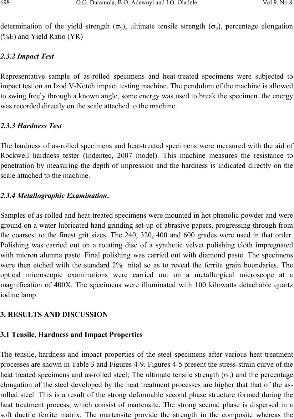 698 O.O. Daramola, B.O. Adewuyi and I.O. Oladele Vol.9, No.8 determination of the yield strength (y), ultimate tensile strength (u), percentage elongation (%E) and Yield Ratio (YR) 2.3.2 Impact Test Representative sample of as-rolled specimens and heat-treated specimens were subjected to impact test on an Izod V-Notch impact testing machine. The pendulum of the machine is allowed to swing freely through a known angle, some energy was used to break the specimen, the energy was recorded directly on the scale attached to t he machine. 2.3.3 Hardness Test The hardness of as-rolled specimens and heat-treated specimens were measured with the aid of Rockwell hardness tester (Indentec, 2007 model). This machine measures the resistance to penetration by measuring the depth of impression and the hardness is indicated directly on the scale attached to the m a c h in e . 2.3.4 Metallographic Examination. Samples of as-rolled and heat-treated specimens were mounted in hot phenolic powder and were ground on a water lubricated hand grinding set-up of abrasive papers, progressing through from the coarsest to the finest grit sizes. The 240, 320, 400 and 600 grades were used in that order. Polishing was carried out on a rotating disc of a synthetic velvet polishing cloth impregnated with micron alumna paste. Final polishing was carried out with diamond paste. The specimens were then etched with the standard 2% nital so as to reveal the ferrite grain boundaries. The optical microscopic examinations were carried out on a metallurgical microscope at a magnification of 400X. The specimens were illuminated with 100 kilowatts detachable quartz iodine lam p. 3. RESULTS AND DISCUSSION 3.1 Tensile, Hardness and Impact Properties The tensile, hardness and impact properties of the steel specimens after various heat treatment processes are shown in Table 3 and Figures 4-9. Figures 4-5 present the stress-strain curve of the heat treated specimens and as-rolled steel; The ultimate tensile strength (u) and the percentage elongation of the steel developed by the heat treatment processes are higher that that of the as- rolled steel. This is a result of the strong deformable second phase structure formed during the heat treatment process, which consist of martensite. The strong second phase is dispersed in a soft ductile ferrite matrix. The martensite provide the strength in the composite whereas the 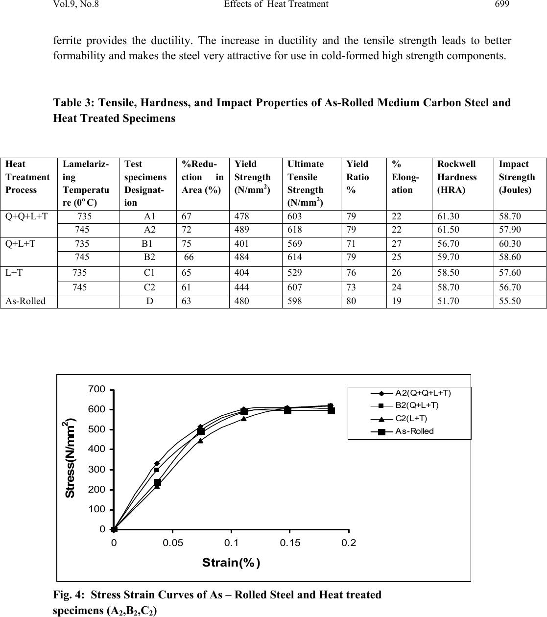 Vol.9, No.8 Effects of Heat Treatment 699 ferrite provides the ductility. The increase in ductility and the tensile strength leads to better formability and makes the steel very attractive for use in cold-formed high strength components. Table 3: Tensile, Hardness, and Impact Properties of As-Rolled Medium Carbon Steel and Heat Treated Specimens Heat Treatment Process Lamelariz- ing Temperatu re (0o C) Test specimens Designat- ion %Redu- ction in Area (%) Yield Strength (N/mm2) Ultimate Tensile Strength (N/mm2) Yield Ratio % % Elong- ation Rockwell Hardness (HRA) Impact Strength (Joules) Q+Q+L+T 735 A1 67 478 603 79 22 61.30 58.70 745 A2 72 489 618 79 22 61.50 57.90 Q+L+T 735 B1 75 401 569 71 27 56.70 60.30 745 B2 66 484 614 79 25 59.70 58.60 L+T 735 C1 65 404 529 76 26 58.50 57.60 745 C2 61 444 607 73 24 58.70 56.70 As-Rolled D 63 480 598 80 19 51.70 55.50 0 100 200 300 400 500 600 700 00.05 0.1 0.15 0.2 Strain(%) Stress(N/mm 2 ) A2(Q+Q+L+T) B2(Q+L+T) C2(L +T) As-Rolled Fig. 4: Stress Strain Curves of As – Rolled Steel and Heat treated specimens (A2,B2,C2) 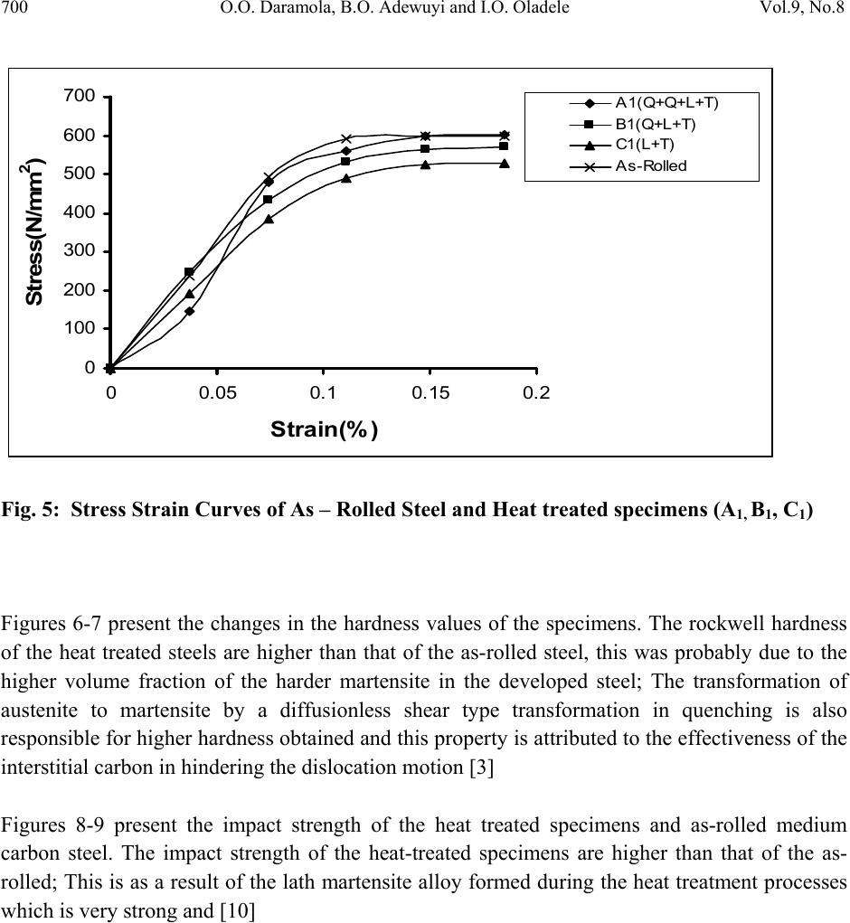 700 O.O. Daramola, B.O. Adewuyi and I.O. Oladele Vol.9, No.8 0 100 200 300 400 500 600 700 00.05 0.10.15 0.2 Strain(%) Stress(N/mm 2 ) A1 (Q+Q+L+T) B1(Q+L+T) C1(L+ T ) As-Rolled Fig. 5: Stress Strain Curves of As – Rolled Steel and Heat treated specimens (A1, B1, C1) Figures 6-7 present the changes in the hardness values of the specimens. The rockwell hardness of the heat treated steels are higher than that of the as-rolled steel, this was probably due to the higher volume fraction of the harder martensite in the developed steel; The transformation of austenite to martensite by a diffusionless shear type transformation in quenching is also responsible for higher hardness obtained and this property is attributed to the effectiveness of the interstitial carbon in hindering the dislocation motion [3] Figures 8-9 present the impact strength of the heat treated specimens and as-rolled medium carbon steel. The impact strength of the heat-treated specimens are higher than that of the as- rolled; This is as a result of the lath martensite alloy formed during the heat treatment processes which is very strong and [10]  Vol.9, No.8 Effects of Heat Treatment 701 46 48 50 52 54 56 58 60 62 64 1 Heat Treatme nt Process Rockwell Hardness (HRA) A1(Q-+Q+L+T) B1(Q+L+T) C1 (L+T) D (As-Rolled) Figure 6: Rockwell Hardness number after various Heat Treatment Processes 46 48 50 52 54 56 58 60 62 64 1 Heat Treatment Process Rockwell Hardness (HRA) A2 (Q-+Q+L+T) B2 (Q+L+T) C2 (L+T) D (As-Rolled) Figure 7: Rockwell Hardness number after various Heat Treatment Processes  702 O.O. Daramola, B.O. Adewuyi and I.O. Oladele Vol.9, No.8 53 54 55 56 57 58 59 60 61 1 Heat Treatment Process Impact Strength (joules) A1 (Q-+Q+L+T) B1 (Q+L+T) C1 (L+T) D (As-Rolled) Figure 8: Impact Strength of Heat Treated Specimens and As–Rolled Medium Carbon Steel. 53.5 54 54.5 55 55.5 56 56.5 57 57.5 58 58.5 59 1 Heat Treatment Proces s Impact S tre ngth (joules) A2 (Q-+Q+L+T) B2 (Q+L+T) C2 (L+T) D (As-Rolled) Figure 9: Impact Strength of Heat Treated Specimens and As–Rolled Medium Carbon Steel  Vol.9, No.8 Effects of Heat Treatment 703 3.2 Microstructures The microstructures obtained are shown in the Plates 1-7. The microstructure produced by the as-rolled steel consist of pearlite while the microstructures produced by Q + Q + L + T, Q + L + T and L + T processes consist of a duplex ferrite martensite microstructure, the strong deformable second phase consists of predominantly of martensite but may contain bainite and retained austenite. The strong second phase is dispersed in a soft ductile ferrite matrix, martensite provides the strength in the composite whereas the ferrite provides the ductility. The L + T and Q+L + T processes increase the ferrite volume fraction resulting in a lower yield strength; Although the volume fraction of the second phase declines, the concentration of carbon raises hardness, which in turn prevents tensile strength from declining. This mechanism allows Q+Q+L + T, Q+L + T, and L + T processes to produce low yield-to-tensile strength ratio of 73% to 79%. Plate 1: Microstructure of As – Rolled 5SP Steel etched in 2% Nital (400X) (Pearlitic Structure)  704 O.O. Daramola, B.O. Adewuyi and I.O. Oladele Vol.9, No.8 Plate 2: Microstructure of Heat Treated Specimen A2 (Q+Q+L+T) (400X) (Duplex Ferrite – Martensite Microstructure) Plate 3: Microstructure of Heat Treated Specimen B2 (Q+L+T) (400X) (Duplex ferrite – Martensite Microstructure 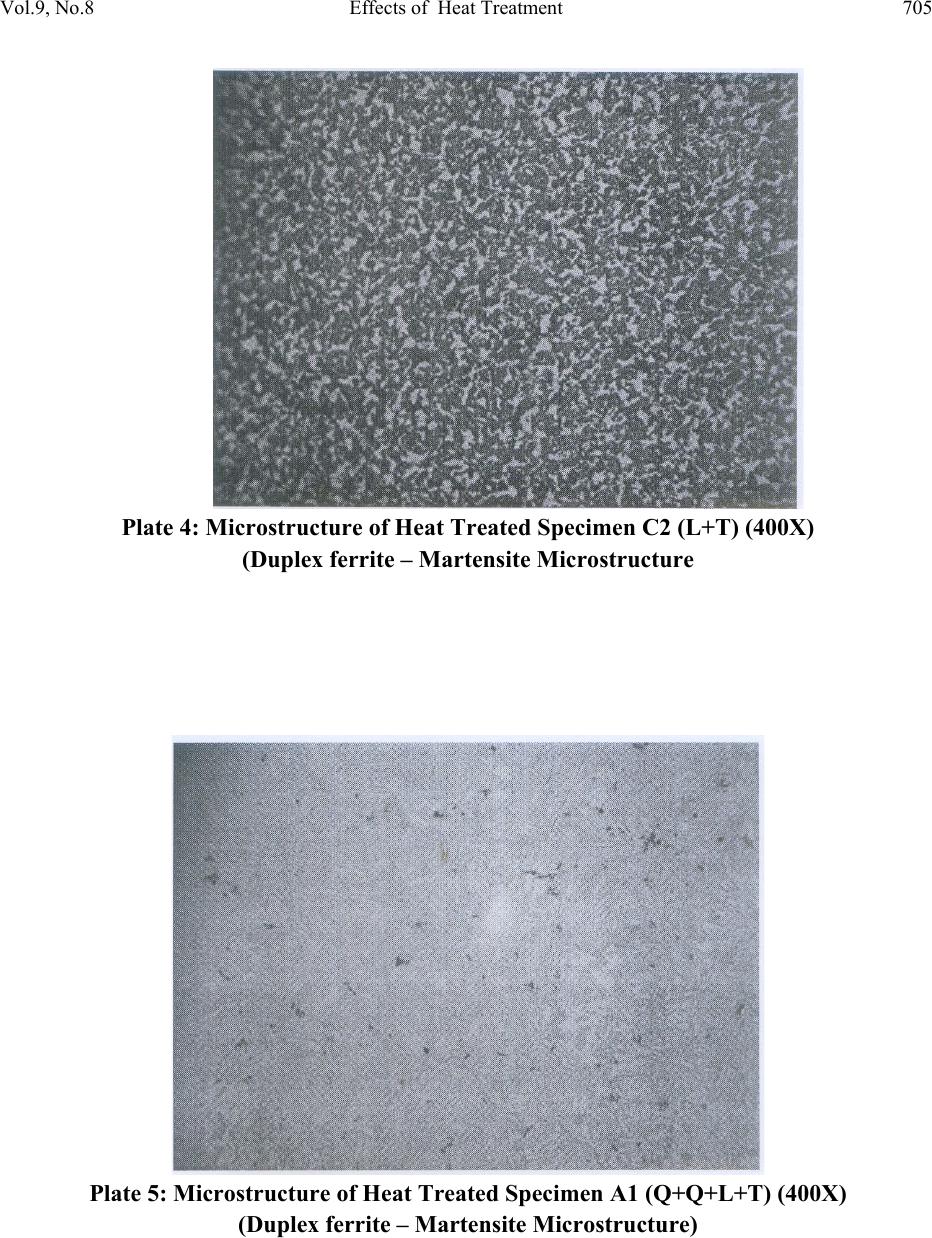 Vol.9, No.8 Effects of Heat Treatment 705 Plate 4: Microstructure of Heat Treated Specimen C2 (L+T) (400X) (Duplex ferrite – Martensite Microstructure Plate 5: Microstructure of Heat Treated Specimen A1 (Q+Q+L+T) (400X) (Duplex ferrite – Martensite Microstructure) 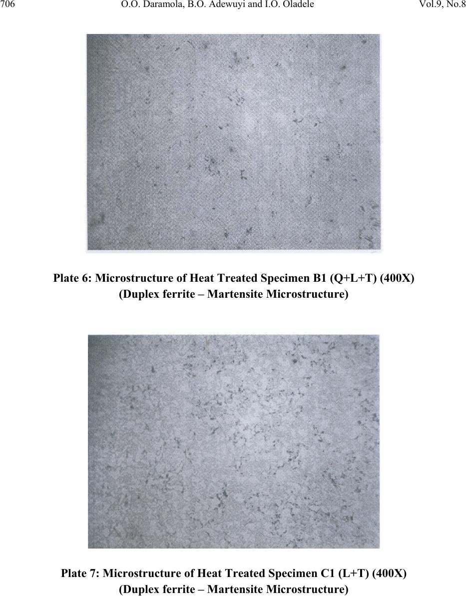 706 O.O. Daramola, B.O. Adewuyi and I.O. Oladele Vol.9, No.8 Plate 6: Microstructure of Heat Treated Specimen B1 (Q+L+T) (400X) (Duplex ferrite – Martensite Microstructure) Plate 7: Microstructure of Heat Treated Specimen C1 (L+T) (400X) (Duplex ferrite – Martensite Microstructure) 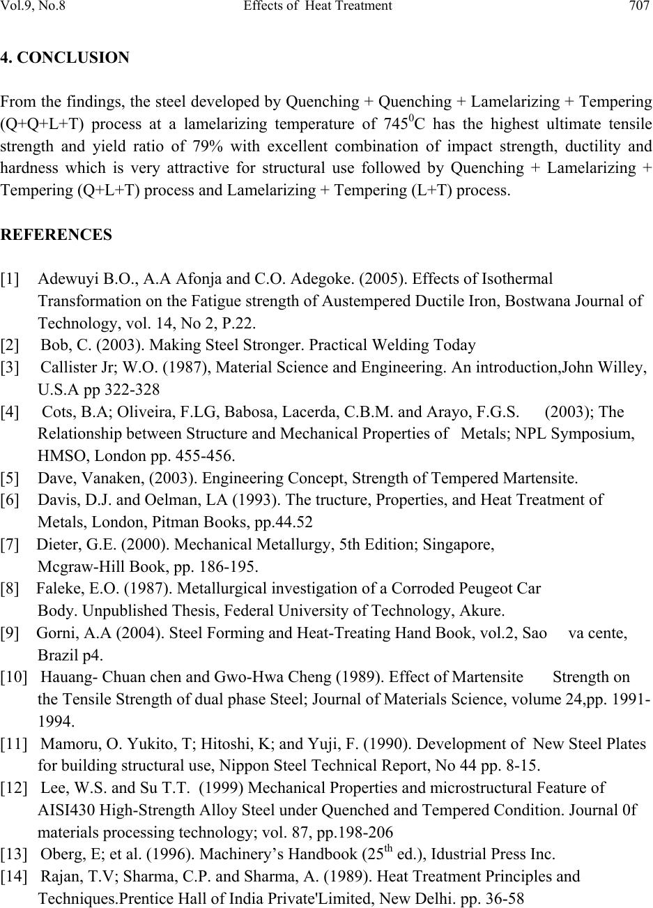 Vol.9, No.8 Effects of Heat Treatment 707 4. CONCLUSION From the findings, the steel developed by Quenching + Quenching + Lamelarizing + Tempering (Q+Q+L+T) process at a lamelarizing temperature of 7450C has the highest ultimate tensile strength and yield ratio of 79% with excellent combination of impact strength, ductility and hardness which is very attractive for structural use followed by Quenching + Lamelarizing + Tempering (Q+L+T) process and Lamelarizing + Tempering (L+T) process. REFERENCES [1] Adewuyi B.O., A.A Afonja and C.O. Adegoke. (2005). Effects of Isothermal Transformation on the Fatigue strength of Austempered Ductile Iron, Bostwana Journal of Technology, vol. 14, No 2, P.22. [2] Bob, C. (2003). Making Steel Stronger. Practical Welding Today [3] Callister Jr; W.O. (1987), Material Science and Engineering. An introduction,John Willey, U.S.A pp 322-328 [4] Cots, B.A; Oliveira, F.LG, Babosa, Lacerda, C.B.M. and Arayo, F.G.S. (2003); The Relationship bet we en Str uct ure an d Mec han ica l Properties of Metals; NPL Symposium, HMSO, London pp. 455-456. [5] Dave, Vanaken, (2003). Engineering Concept, Strength of Tempered Martensite. [6] Davis, D.J. and Oelman, LA (1993). The tructure, Properties, and Heat Treatment of Metals, London, Pitman Books, pp.44.52 [7] Dieter, G.E. (2000). Mechanical Metallurgy, 5th Edition; Singapore, Mcgraw-Hill Book, pp. 186-195. [8] Faleke, E.O. (1987). Metallurgical investigation of a Corroded Peugeot Car Body. Unpublished Thesis, Federal University of Technology, Akure. [9] Gorni, A.A (2004). Steel Forming and Heat-Treating Hand Book, vol.2, Sao va cente, Brazil p4. [10] Hauang- Chuan chen and Gwo-Hwa Cheng (1989). Effect of Martensite Strength on the Tensile Strength of dual p h ase Steel; Journal of Materials Science, volume 24,pp. 1991- 1994. [11] Mamoru, O. Yukito, T; Hitoshi, K; and Yuji, F. (1990). Development of New Steel Plates for building structural use, Nippon Steel Technical Report, No 44 pp. 8-15. [12] Lee, W.S. and Su T.T. (1999) Mechanical Prope r ties and microstructural Feature of AISI430 High-Strength A l lo y S te e l un d er Q u enched and Tempered Condition. Journal 0f materials processing technology; vol. 87, pp.198-206 [13] Oberg, E; et al. (1996). Machinery’s Handbook (25th ed.), Idustrial Press Inc. [14] Rajan, T.V; Sharma, C.P. and Sharma, A. (1989). Heat Treatment Principles and Techniques.Prentice Hall of India Private'Limited, New Delhi. pp. 36-58 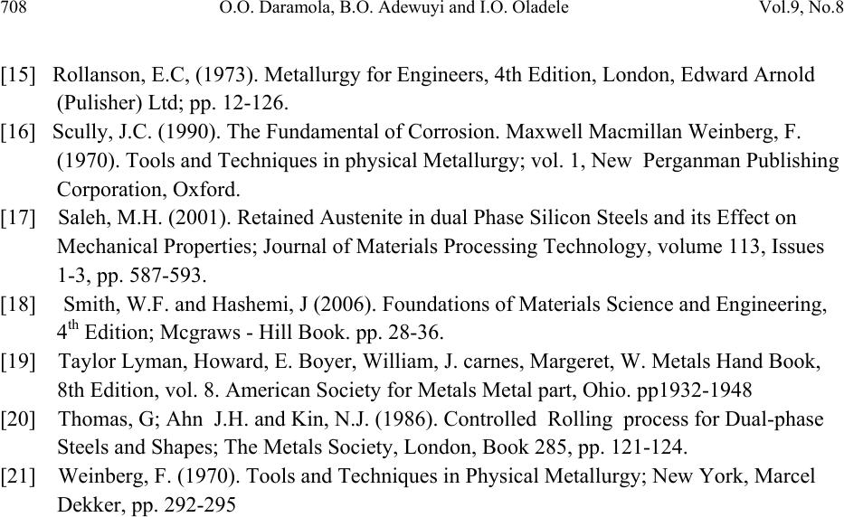 708 O.O. Daramola, B.O. Adewuyi and I.O. Oladele Vol.9, No.8 [15] Rollanson, E.C, (1973). Metallurgy for Engineers, 4th Edition, London, Edward Arnold (Pulisher) Ltd; pp. 12-126. [16] Scully, J.C. (1990). The Fundamental of Corrosion. Maxwell Macmillan Weinberg, F. (1970). Tools and Techniques in physical Metallurgy; vol. 1, New Perganman Publishing Corporation, Oxford. [17] Saleh, M.H. (2001). Retained Austenite in dual Phase Silicon Steels and its Effect on Mechanical Properties; Journal of Materials Processing Technology, volume 113, Issues 1-3, pp. 587-593. [18] Smith, W.F. and Hashemi, J (2006). Foundations of Materials Science and Engineering, 4th Edition; Mcgraws - Hill Book. pp. 28-36. [19] Taylor Lyman, Howard, E. Boyer, William, J. carnes, Margeret , W. Metals Hand Book, 8th Edition, vol. 8. American Society for Metals Metal part, Ohio. pp1932-1948 [20] Thomas, G; Ahn J.H. and Kin, N.J. (1986). Controlled Rolling process for Dual-phase Steels and Shapes; The Metals Society, London, Book 285, pp. 121-124. [21] Weinberg, F. (1970). Tools and Techniques in Physical Metallurgy; New York, Marcel Dekker, pp. 292-295 |