Paper Menu >>
Journal Menu >>
 Journal of Minerals & Materials Characterization & Engineering, Vol. 9, No.7, pp.581-591, 2010 jmmce.org Printed in the USA. All rights reserved 581 Design of a Diesel Fired Heat-Treatment Furnace *K.K. Alaneme and S.O. Olanrewaju Department of Metallurgical and Materials Engineering Federal University of Technology, Akure, PMB 704, Nigeria *Corresponding Author: kalanemek@yahoo.co.uk ABSTRACT This research is centered on the design of a diesel fired heat-treatment furnace using locally sourced materials. The design philosophy is to eliminate the use of heating elements requiring electric power which is poorly supplied in the country. Design drawings were produced and mild steel was used for the fabrication of the furnace casing, while the other components needed for the design were selected based on functionality, durability, cost and local availability. The furnace was assembled by lining the inner wall of the casing with refractory blocks made from heated mixture of kaolin, clay, sawdust and water after which the inner pot and electro technical devices (temperature controller, light indicator etc) were positioned. Testing was subsequently performed to evaluate the performance of the furnace. It was observed that the furnace has a fast heating rate (61.240C/min to attain a pre-set temperature of 9000C); and a fuel consumption rate less than 1.41litres/hr. It was also observed that the furnace has good heat retaining capacity; can be easily maintained and safe for use. Keywords: Diesel-fired; Furnace; Refractory; Design; Performance 1. INTRODUCTION The modification of microstructures to achieve desired properties is a fundamental approach in metallic materials development. Heat-treatment which is one of the primary routes of developing microstructures requires the use of furnaces to be able to attain desired temperatures, heating and cooling rates; and holding environments required to induce phase transformations [1]. Heat- treatment furnaces with effective temperature sensing, heat retaining capacity and controlled environment are necessary for heat-treatment operations to be successfully performed. Some of  582 K.K. Alaneme and S.O. Olanrewaju Vol.9, No.7 the processes require heating cycles for durations spanning a few minutes to several hours depending of the material and the properties desired [2 – 3]. The absence of constant power supply in the country has made it difficult for a wide range of heat-treatment operations to be effectively performed. In the Universities and research institutes this situation has affected research output for many research scholars who are interested in microstructure development through heat-treatment. This challenge is the motivation for this research aimed at the development of a portable heat-treating furnace that relies on diesel to fire and generate the heat needed to raise the temperature of the furnace to the desired level. The elimination of the use of heating elements which requires electric power to function is the fundamental design principle justifying the research work. A good number of research works have been reported on the design of furnaces to meet the needs of the Nigerian scientific and technological environment [4 -5]; but very little literature is available on the design of diesel fired heat-treatment furnaces. The design on completion will significantly reduce the dependence on electric muffle furnaces and guarantee uninterrupted experimental heat-treatment research work. 2. MATERIALS AND METHOD 2.1 Materials The materials utilized for the design of the diesel fired heat-treatment furnace are: 2mm thick steel sheets, kaolin clay derived from two deposits in south western Nigeria – Ijapo and Ikere Clays, silica refractory bricks, hard wood saw dust, temperature controller, thermocouple, switch, light indicators, w ire, diesel, plug, burner, and chrome based alloy steel pot. 2.2 Design 2.2.1 Furnace casing The steel sheet selected is a mild steel of composition: 0.15%C, 0.45%Mn, 0.18%Si, 0.18%Si, 0.031%S, 0.001%P, 0.0005%Al, 0.0008%Ni and balance Fe. It was selected for the fabrication of the furnace casing because of its light weight, good strength, excellent formability, weldability, availability, and low cost of purchase. The furnace casing houses all the components of the furnace including: the refractory bricks and lining, the electro-technical devices (temperature controller, light indicator etc), the burner, exhaust, and heat-treating pot (chamber). The design was made taking into consideration that the control box should be attached to the casing, and the control box must have holes for easy wiring and uniform de-steaming. The size of the burner was utilized in the design of the burner nose inlet. The configuration of the exhaust duct was made rectangular and big enough to give allowance for lining. The exhaust was made long enough to ensure the expulsion of exhaust gases far away from the heat-treating environment to ensure safety of the operator. The design drawings are presented in Figure 1. 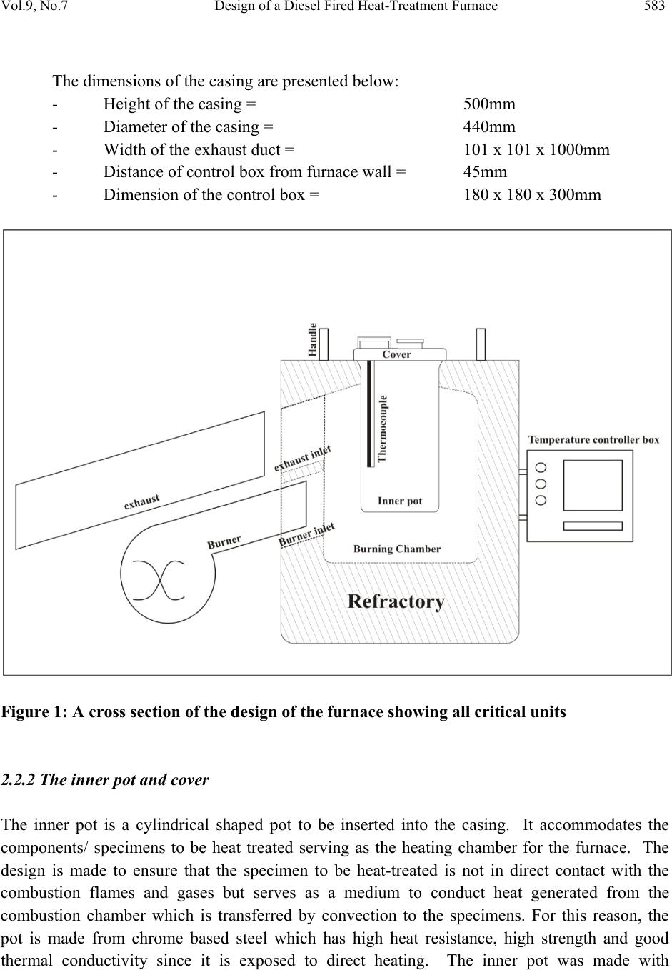 Vol.9, No.7 Design of a Diesel Fired Heat-Treatment Furnace 583 The dimensions of the casing are presented below: - Height of the casing = 500mm - Diameter of the casing = 440mm - Width of the exhaust duct = 101 x 101 x 1000mm - Distance of control box from furnace wall = 45mm - Dimension of the control box = 180 x 180 x 300mm Figure 1: A cross section of the design of the furnace showing all critical units 2.2.2 The inner pot and cover The inner pot is a cylindrical shaped pot to be inserted into the casing. It accommodates the components/ specimens to be heat treated serving as the heating chamber for the furnace. The design is made to ensure that the specimen to be heat-treated is not in direct contact with the combustion flames and gases but serves as a medium to conduct heat generated from the combustion chamber which is transferred by convection to the specimens. For this reason, the pot is made from chrome based steel which has high heat resistance, high strength and good thermal conductivity since it is exposed to direct heating. The inner pot was made with  584 K.K. Alaneme and S.O. Olanrewaju Vol.9, No.7 dimensions 10mm thickness, 140mm diameter and 200mm length. The base was covered with double layers of the same steel material making its thickness 20mm. A circular flange was constructed round the pot to hold it in place during the assembly. Two rings were welded to the flange to hold the specimens in place during heat treatment. The cover also was made from the 2mm mild steel flat sheet. The cover was fitted with a peep hole and a handle for opening the furnace for placement of specimens for heat-treatment. 2.3 Fabrication Procedure 2.3.1 Furnace casing The casing was made from a 2mm thick flat sheet of mild steel. The sheet was cut to height of 500mm and then rolled into a cylinder with diameter of 440mm. The folding joint was seam welded for strength and rigidity. A circular plate of diameter 440mm was cut and seam welded to cover the bottom of the cylinder to form the casing. A rectangular hole of 100x100mm was cut for the exhaust 126mm from the upper part of the casing and a circular hole at the bottom making a horizontal angle of 450 to the exhaust hole. A flat sheet folded into square box shape of 100x100x100mm was welded to the exhaust hole to form the exhaust. Another detachable exhaust pipe was fabricated to release the smoke into the atmosphere. A square pipe of 101x101x1000mm was formed from the sheet of mild steel and seam welded. Next was the electro-technical units housing, which was formed by folding a sheet into a hollow square box of dimension 180x180x300mm. One end of the box was covered with a flat sheet of 180x180mm. Both piece are welded together and then to the body of the casing with some allowance between the body and the housing. The housing is tilted 300 to the vertical for easy viewing when standing. A cover is then made for the other end of the box but it is not welded but to carry the devices by screwing and then used to cover the box by just keying in. this is actually removable. Another circular hole of 100mm in diameter is cut at the lower end of the casing to accommodate the burner for firing the heating chamber. 2.3.2 Refractory lining The refractory lining for the furnace was made by blending Ijapo Clay, Ikere Clay (which is rich in kaolin); fine saw dust of hard wood, and water in the ratio 4:12:3:1 by volume percent. The thoroughly blend mixture was cast into trapezoidal and rectangular shapes. The clay mould lining was allowed to air dry for at least one week, after which the lining was fired at progressively increasing temperature cycles ranging from 1000C – 10000C for between 3 – 48 hours. The saw dust in the mixture is burnt off during the heating leaving pores which contribute to the insulative property of the refractory lining. The lining of the furnace involves three stages:  Vol.9, No.7 Design of a Diesel Fired Heat-Treatment Furnace 585 • Flooring: this is done by first lining round the internal casing wall with refractory to create support and filling the centre of the base with dry sand. The surface of which made wet with water for setting after the walls of the furnace has been lined; • Setting of bricks: the wall of the furnace is then lined with refractory bricks which are held by a plaster made of the mixture of clay, kaolin, and water. The inner pot is then carefully place and final plastering and finishing touch is carried out; and • Drying: the assembly is then allowed to dry for two weeks and any breach or cracks observed are repaired as the clay dries. The clay contracts and cracks during drying which necessitates proper repair to enhance the working efficiency and life span of the furnace. The refractory materials utilized are shown in Figure 2. Figure 2: Locally Sourced Refractory Materials and Bricks 2.4 Assembly The parts to be assembled include: the casing and inner pot, the refractory, the burner and the electro-technical devices. The casing is first positioned and lined with refractory up to 100mm thickness on the sides and 200mm at the floor and plastered with a mixture of kaolin and clay with binder. The pot is then placed in the casing and held by refractory at the flanges leaving a combustion zone of 50mm round the pot and 100mm between the base of the pot and the flooring. The casing, inner pot, and the refractory are left for days to dry. The refractory shrinks due to loss of water thereby opening up some gaps. These breaches are then repaired using more refractory mixture to plaster. This process is done to prevent explosion or loss of heat due to improper refractory moulding and support. The furnace cover and job holder are also fixed. The exhaust pipe is then fitted. The casing is designed such that the exhaust hole protrudes outward preventing heat concentration at the exit which can damage the furnace. The protruded  586 K.K. Alaneme and S.O. Olanrewaju Vol.9, No.7 length is about 100mm being 2mm smaller the dimension of the inner cross section of the exhaust pipe. This is to aid the unidirectional flow of heat and smoke out of the chamber through convection. Next is the burner. It is placed in the hole at an angle of 450 on the horizontal plane below the exhaust. The position is to allow for homogenous and enough heat residential time in the burning chamber before heat exit through the exhaust. The burner is placed in such a way that the flame is directed to the bottom of the pot at some distance away from it. With this setting the temperature in the burning zone could be as high as 11000C in the burning chamber and 900- 10000C in the inner pot. The electro-technical devices are then connected for the automation of the furnace system. This involves the connection of the thermocouple through the thermocouple lead to the temperature controller. The controller switches on and off the burner as the set temperature is reached. This controller box is joined to the furnace but separated with few centimeters to avoid heating the temperature controller devices. The controller box is tilted 300 to the vertical for easy viewing even while standing. The furnace is switched on via an industrial switch and the working progress indicated by LED indicator light. 2.5 Electrical Connection This involves the connection between the electro –technical devices and the burner for the functionality of the furnace. The thermocouple is placed in the inner pot to read temperature and it is connected to the temperature controller. AC current is connected to the system via an industrial switch. A flexible cable is used to connect the life of the current to the switch. The switch is then connected to the temperature controller. The timer is then used to connect the controller to the sparker transformer for ignition of the burner using the flexible cable. Also the controller is directly connected to the pump of the burner to supply fuel for combustion. LED indicator lights are also connected in such a way that they indicate when the furnace is on, the burner is turned on and the furnace is working respectively. Figure 3 shows the electrical circuit diagram for the furnace.  Vol.9, No.7 Design of a Diesel Fired Heat-Treatment Furnace 587 Figure 3: Electrical Circuit Diagram for the Furnace 3. PERFORMANCE EVALUATION The performance of the diesel fired heat-treating furnace was evaluated by considering the functionality and efficiency of the furnace, ease of maintenance, safety and health considerations, and the cost effectiveness of the furnace. 3.1 Functionality and Efficiency of the Furnace The thermocouple tip is positioned in the furnace inner pot (1/3) one – third from the base close to the position the specimens are anchored to ensure that accurate temperature of the specimen and not that of the furnace environment is sensed. Also, the temperature controller is digital with the capability of sensing fractions of temperature thereby improving the precision and accuracy of the readings obtained from the furnace. Regular calibration of the temperature controller using an external probe is performed to ensure reliability of the temperature readings obtained from the furnace. The furnace has a high heating rate – as fast as 61.240C/min if a temperature of 9000C is the target holding temperature. This rate of heating is far higher than that of many conventional muffle furnaces which take between 3.75 – 5.000C/min to attain 9000C. Thus within 17 minutes a  588 K.K. Alaneme and S.O. Olanrewaju Vol.9, No.7 temperature of 9000C can be attained resulting in time savings. Also the fuel consumption rate is less than 1.41 litres/hr. This consumption rate reduces the longer the holding time during heat- treatment because the design is made to switch off the fuel supply to the burner once the temperature of the furnace exceeds the preset temperature of the furnace by 20C and then restored automatically once the temperature drops 20C from the pre-set temperature. Thus fuel savings will be achieved for longer holding times. The furnace refractory was observed to have good heat retaining capacity, as temperatures within 9500C and below, the heat from the furnace environment is tolerable for the operator and those in the surrounding. This indicates that the refractory linings have good efficiency and effectiveness in the prevention of heat transfer from the heating chamber to the surroundings. 3.2 Safety and Maintenance The thermocouple should not be removed from its position in the inner pot, as its removal will result in the overheating and damage to the inner pot of the furnace. During operation, it is mandatory to have more than the estimated fuel supply to ensure that there is no cut in the supply of fuel to the burner which could result in explosion. Regular calibration of the temperature controller is required to ensure that accurate readings are obtained. The specimens for heat- treatment should be properly dried before inserting into the furnace as moisture from the specimens could explode and cause damage to the furnace during usage [6]. Fluctuating power voltage to the burner should be avoided as it can cause damage to the blower motor. Also, servicing of the blower/pump should be carried out at least twice a year to guarantee optimum performance of the furnace. The operator should always put on personal protection equipment (safety gadgets) such as hand gloves, heat protectors; and after the days work ensure that beverage rich in milk is taken to compensate for the effects of heat radiation from the furnace [7]. The furnace is positioned in a well ventilated environment to avoid suffocation and proper elimination of CO2 gas produced as shown in Figure 4. The design makes it easy for all the parts of the furnace to be easily detached for repairs when the need arises, and damaged parts can be easily replaced since all parts are r e latively cheap and are sourced locally. 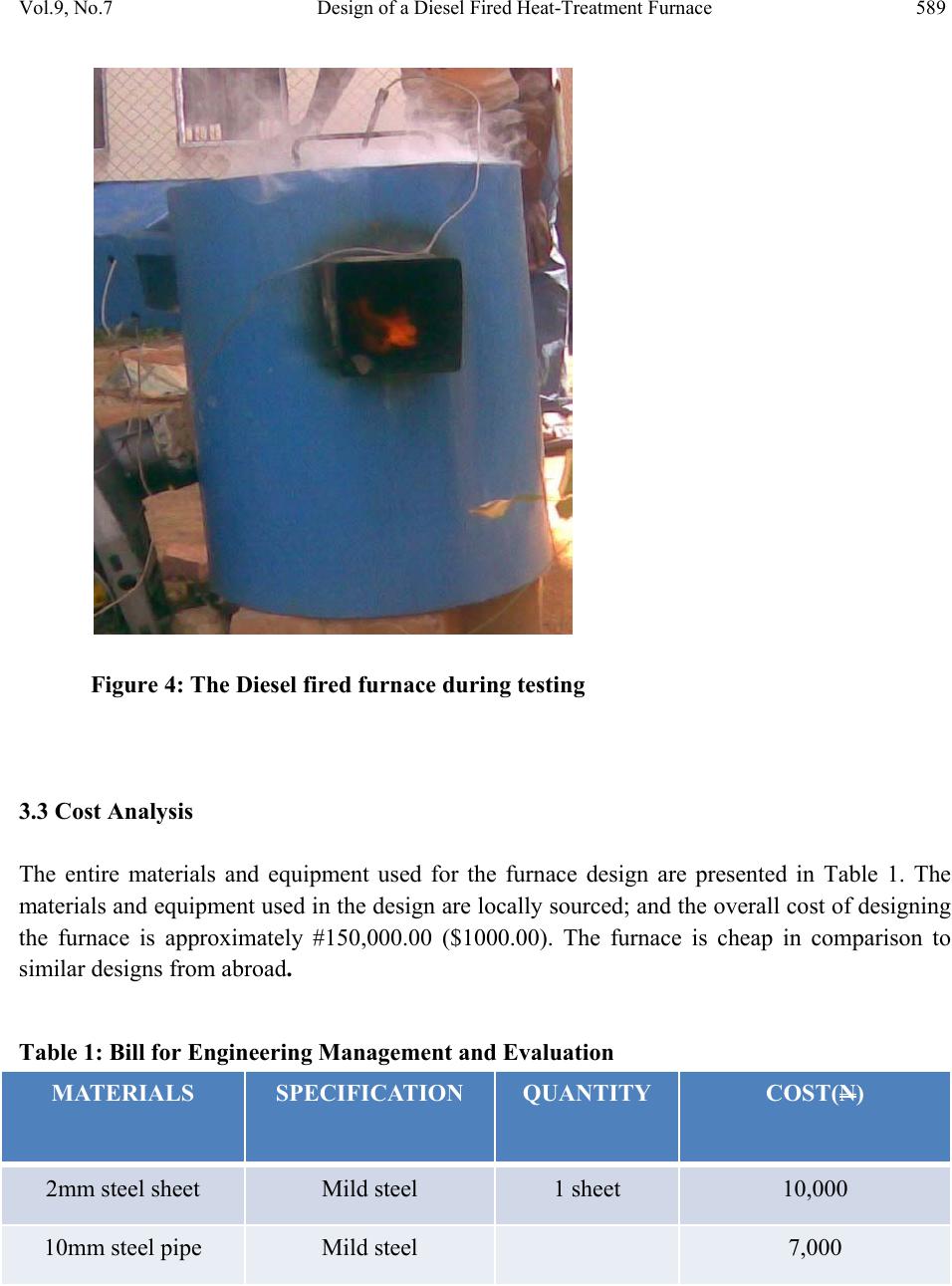 Vol.9, No.7 Design of a Diesel Fired Heat-Treatment Furnace 589 Figure 4: The Diesel fired furnace during testing 3.3 Cost Analysis The entire materials and equipment used for the furnace design are presented in Table 1. The materials and equipment used in the design are locally sourced; and the overall cost of designing the furnace is approximately #150,000.00 ($1000.00). The furnace is cheap in comparison to similar designs from abroad. Table 1: Bill for Engineering Management and Evaluation MATERIALS SPECIFICATION QUANTITY COST(N) 2mm steel sheet Mild steel 1 sheet 10,000 10mm steel pipe Mild steel 7,000  590 K.K. Alaneme and S.O. Olanrewaju Vol.9, No.7 100x100mm² pipe Mild steel 3,200 Body filler 2 300 Paint Premier 2 Red oxide Apex 1/4tin 100 Electrode Mild steel ½ packet 600 Silica bricks Lot 4,000 Binder & kaolin Lot 3,000 Burner. sparker, etc 1 45,000 Temp. controller Nutronix 1 40,000 Thermocouple Nutronix 1 2,800 Timer Nutronix 1 2,500 Switch Nutronix 1 600 Plug 15 Amps 1 100 Wire Industrial & Flexible lot 2,000 Tape Black & Thread 3 300 Transportation 5,000 Labour 7,000 TOTAL 133,500  Vol.9, No.7 Design of a Diesel Fired Heat-Treatment Furnace 591 4. CONCLUSION This research was centered on the design of a diesel fired heat-treatment furnace using locally sourced materials. The design philosophy is to eliminate the use of heating elements requiring electric power which is poorly supplied in the country. On completion and testing, it was observed that the furnace has a fast heating rate (61.240C/min to attain a pre-set temperature of 9000C); and very good fuel economy – consuming less than 1.41litres/hr. It was also observed that the furnace has good heat retaining capacity; can be easily maintained and is safe for use. REFERENCES 1. Dossee, T. and Boyer, H. Practical Heat Treating. Journal of Materials Processing Technology, 1997, 14(7): 235-257. 2. George, E. Totten: Steel Heat Treatment Handbook, 2nd Edition; 2002, pp 91-105. 3. Netsushori, K.: Various Heat Treatment Technology. Trends and prospects of heat treatment in 21st Century. 3rd Edition. 1998, pp. 201-233. 4. Olanrewaju, S.O.: Practical approach to metal hardening in our metallurgical industries, NMS Conference, National Metallurgical Development Center (NMOC), Jos, 2000, pp 6- 15. 5. Oyawale, F. A. (2007): Design and Prototype development of a mini-Electric Arc Furnace. Pacific Journal of Science and Technology. 2007, 8(1):12 – 16. 6. Bundgardt, K., Brandis, H. and Kroy, P. Salt Bath Carburizing and Case Hardened Steels at 9000C – 10000C., Harterei-technical publisher, 1994,19(3): 146-153. 7. Fairbanks, L.H. and Palthorpe, L.G.W.: Controlled Atmospheres for Heat Treatment of Metals. Revised Edition; Iron and Steel Institutes, Spain. 1998, pp. 45-60. |

