Paper Menu >>
Journal Menu >>
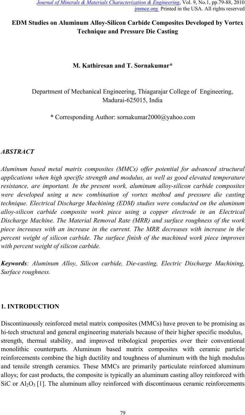 Journal of Minerals & Materials Characterization & Engineering, Vol. 9, No.1, pp.79-88, 2010 jmmce.org Printed in the USA. All rights reserved 79 EDM Studies on Aluminum Alloy-Silicon Carbide Composites Developed by Vortex Technique and Pressure Die Casting M. Kathiresan and T. Sornakumar* Department of Mechanical Engineering, Thiagarajar College of Engineering, Madurai-625015, India * Corresponding Author: sornakumar2000@yahoo.com ABSTRACT Aluminum based metal matrix composites (MMCs) offer potential for advanced structural applications when high specific strength and modulus, as well as good elevated temperature resistance, are important. In the present work, aluminum alloy-silicon carbide composites were developed using a new combination of vortex method and pressure die casting technique. Electrical Discharge Machining (EDM) studies were conducted on the aluminum alloy-silicon carbide composite work piece using a copper electrode in an Electrical Discharge Machine. The Material Removal Rate (MRR) and surface roughness of the work piece increases with an increase in the current. The MRR decreases with increase in the percent weight of silicon carbide. The surface finish of the machined work piece improves with percent weight of silicon carbide. Keywords: Aluminum Alloy, Silicon carbide, Die-casting, Electric Discharge Machining, Surface roughness. 1. INTRODUCTION Discontinuously reinforced metal matrix composites (MMCs) have proven to be promising as hi-tech structural and general engineering materials because of their higher specific modulus, strength, thermal stability, and improved tribological properties over their conventional monolithic counterparts. Aluminum based matrix composites with ceramic particle reinforcements combine the high ductility and toughness of aluminum with the high modulus and tensile strength ceramics. These MMCs are primarily particulate reinforced aluminum alloys; for cast products, the composite is typically an aluminum casting alloy reinforced with SiC or Al2O3 [1]. The aluminum alloy reinforced with discontinuous ceramic reinforcements  80 M. Kathiresan and T. Sornakumar Vol.9, No.1 is rapidly replacing conventional materials in various automotive, aerospace and automobile industries [2]. Electrical discharge machining (EDM) is a non-traditional manufacturing process where the material is removed by a succession of electrical discharges, which occur between the electrode and the work piece. These are submersed in a dielectric liquid such as kerosene or deionised water. The electrical discharge machining process is widely used in the aerospace, automobile and moulds industries to machine hard metals and its alloys. During the electrical discharge, a discharge channel is created where the temperature reaches approximately 12,000 0C, removing material by evaporation and melting from both the electrode and the work piece. When the discharge ceases there is a high cooling on the surface of the work piece creating a zone affected by the heat that contains the white layer. Electrical discharge machining is governed by a thermal phenomenon therefore not only removes material from the work piece but also changes the metallurgical constituents in the zone affected by the heat [3]. Metal matrix composites (MMCs) contain a certain amount of secondary hard and abrasive reinforcements to give high strength, hardness and stiffness. However the machining of MMCs using conventional tool materials is very difficult due to the presence of the abrasive reinforcing phases, which cause severe tool wear. The greater the reinforcement in a composite the faster is the tool wear. Thus non-traditional machining like electric discharge machining (EDM) can be used to perform the precision machining of MMCs [4]. Metal matrix composites (MMCs) are well known for their superior mechanical properties over un- reinforced alloys . These composite material s are composed of a metallic base material called matrix, which is reinforced with ceramic fiber, whisker or particulates that impart a combination of properties not achievable in either of the constituents individually. A full scale application of these advanced materials however has been hindered due to their high cost of machining. They can be machined with either electroplated diamond-grinding wheel or with carbide / poly crystalline diamond cutting tools. In view of difficulties encountered e.g. high tool wear and high tooling cost, during conventional machining, non-contact material removal processes such as the electric discharge machining (EDM) offer an effective alternative [5]. Lloyd (1994) reported that vortex mixing technique was suitable for the preparation of ceramic particle dispersed aluminum composite [6]. The vortex mixing technique for the preparation of ceramic particle dispersed aluminum matrix composites was developed by Surappa and Rohatgi [7]. The stir casting involves incorporation of ceramic particulate into liquid aluminum melt and allowing the mixture to solidify. Here, the crucial thing is to create good wetting between the particulate reinforcement and the liquid aluminum alloy melt. The simplest and most commercially used technique is known as vortex technique or stir casting technique. The vortex technique involves the introduction of pre-treated ceramic particles into the vortex of molten alloy created by the rotating impeller [8]. Bronze–alumina composite was developed using stir casting method [9].  Vol.9, No.1 EDM Studies on Aluminum Alloy-Silicon Carbide Composites 81 The development of the pressure die casting process should have a priority over other metal casting technologies since it ensures the production of thin walled cast articles of a complicated shape with a high yield and high dimensional precision. Such products effectively do not need further mechanical treatment. A distinctive feature of the process is structural inhomogeneity of metal due to the formation of a fine grained layer 0.3–0.8 mm thick on the surface of die castings. It is formed during the near instantaneous (0.01–0.05 s) solidification in a water cooled die under high pressure [10]. Pressure die casting is a process ideally suited to manufacture mass produced metallic parts of complex shapes requiring precise dimensions. In this process, molten metal is forced into a cold empty cavity of a desired shape and is then allowed to solidify under a high holding pressure. The entire cycle can be divided into three stages, the first or slow speed stage, the second or high speed stage and the third or intensification stage, where hydraulic pressure is exerted to avoid shrinkage or gas problems. The high pressure die comprises two basic parts, the fixed half and the moving or ejector half. When the die is opened, the casting is retained in the moving half, from which it is ejected by pins activated either hydraulically or mechanically [11]. The attractiveness of die casting is its ability to make near net shape parts with tight tolerances and requiring little or no machining. The more applied of the different die casting processes is high pressure die casting (HPDC) with high rates of production. The automotive industry uses an extensive range of aluminum HPDC parts including transmission housings, cylinder heads, inlet manifolds, engine sumps as well as decorative trim. This trend is increasing as replacement of steel parts with lighter aluminum HPDC parts grows (Tharumarajah, 2008) [12]. 2. EXPERIMENTAL PROCEDURE In the present work, aluminum alloy and different weight compositions of silicon carbide were die casted, using LM24 aluminum alloy as the matrix material and silicon carbide particles of average particle size of 16 microns as a reinforcement material. The aluminum alloy was melted in a graphite crucible at a controlled temperature protected with an argon gas atmosphere. The graphite stirrer was introduced into the crucible to perform mixing process when the molten temperature reached 850 0C. The stirring was carried out for 45 minutes at the rate of 200 rpm. Silicon carbide particles were preheated to 200 0C and introduced into the vortex created in the molten alloy. The internal surface of the die was applied with a water based die coat before each casting which acts as a lubricant between the molten metal and die, and also prevents the adhesion between the die cast metal and die. A 420 ton cold chamber hydraulic type die casting machine was used for making the castings. The pouring temperature of molten mixture was 850 0C and molten metal was injected into the runner of the closed die with the initial velocity of 0.23 m/sec up to runner gate. Then the ram movement is given with 1.8 m/sec for injection and simultaneously shot in the die. The molten mixture was poured into the plunger sleeve and forced into the die cavity with pressure of 100 MPa. The shot accumulation force of 420 tons is applied at the end of injection and the die is simultaneously cooled with demineralized water. Then the MMC was 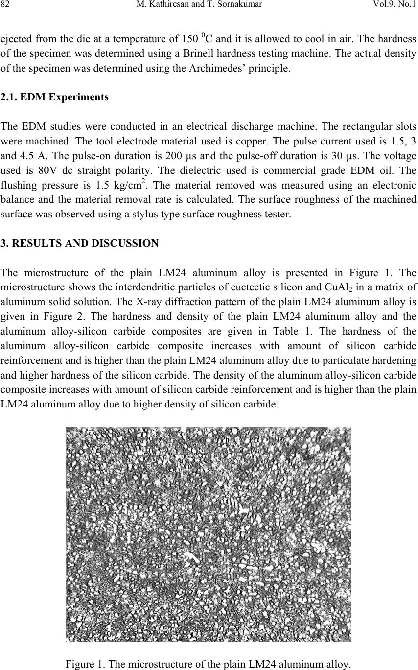 82 M. Kathiresan and T. Sornakumar Vol.9, No.1 ejected from the die at a temperature of 150 0C and it is allowed to cool in air. The hardness of the specimen was determined using a Brinell hardness testing machine. The actual density of the specimen was determined using the Archimedes’ principle. 2.1. EDM Experiments The EDM studies were conducted in an electrical discharge machine. The rectangular slots were machined. The tool electrode material used is copper. The pulse current used is 1.5, 3 and 4.5 A. The pulse-on duration is 200 µs and the pulse-off duration is 30 µs. The voltage used is 80V dc straight polarity. The dielectric used is commercial grade EDM oil. The flushing pressure is 1.5 kg/cm2. The material removed was measured using an electronic balance and the material removal rate is calculated. The surface roughness of the machined surface was observed using a stylus type surface roughness tester. 3. RESULTS AND DISCUSSION The microstructure of the plain LM24 aluminum alloy is presented in Figure 1. The microstructure shows the interdendritic particles of euctectic silicon and CuAl2 in a matrix of aluminum solid solution. The X-ray diffraction pattern of the plain LM24 aluminum alloy is given in Figure 2. The hardness and density of the plain LM24 aluminum alloy and the aluminum alloy-silicon carbide composites are given in Table 1. The hardness of the aluminum alloy-silicon carbide composite increases with amount of silicon carbide reinforcement and is higher than the plain LM24 aluminum alloy due to particulate hardening and higher hardness of the silicon carbide. The density of the aluminum alloy-silicon carbide composite increases with amount of silicon carbide reinforcement and is higher than the plain LM24 aluminum alloy due to higher density of silicon carbide. Figure 1. The microstructure of the plain LM24 aluminum alloy. 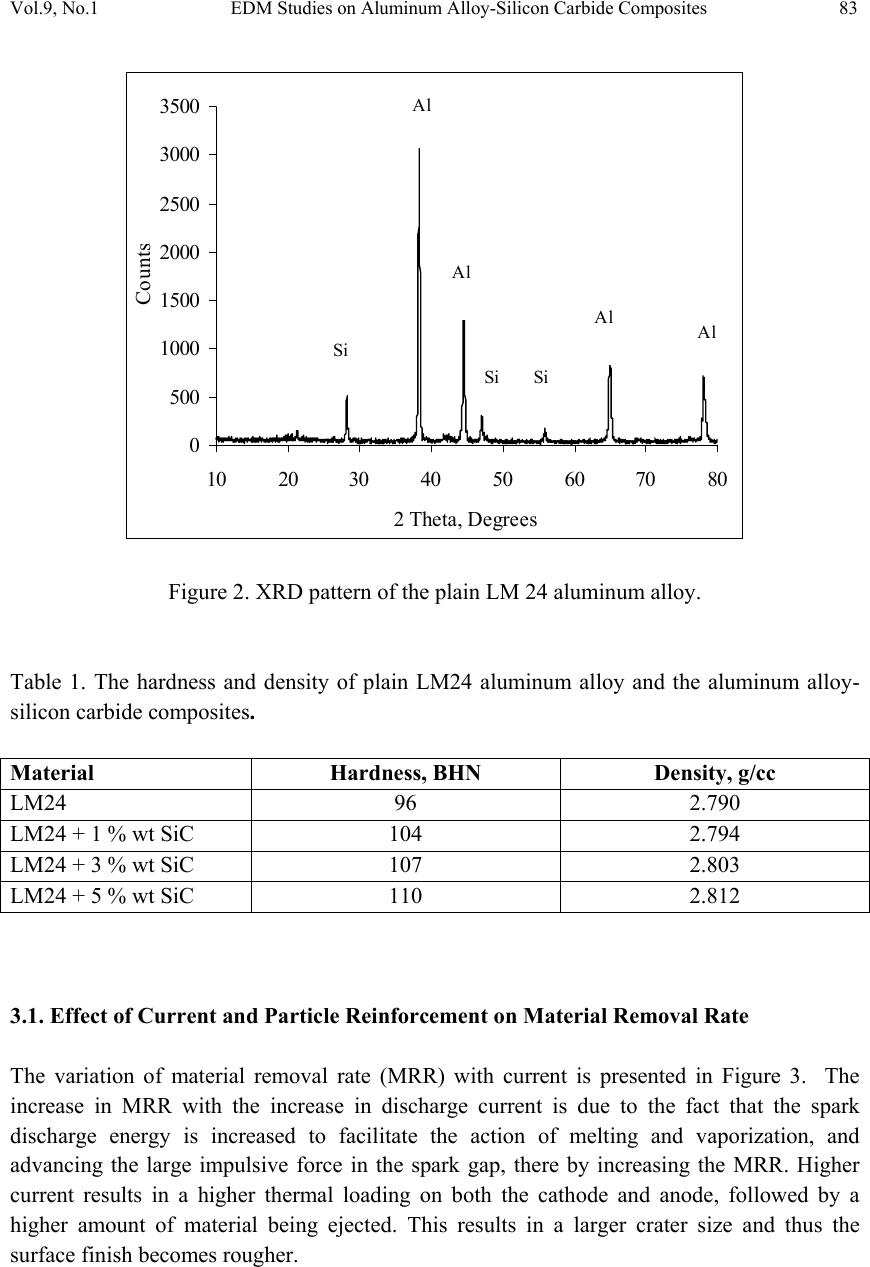 Vol.9, No.1 EDM Studies on Aluminum Alloy-Silicon Carbide Composites 83 0 500 1000 1500 2000 2500 3000 3500 10 2030 40 50 6070 80 2 Theta, Degrees Count s Si Si Al Al Al Si Al Figure 2. XRD pattern of the plain LM 24 aluminum alloy. Table 1. The hardness and density of plain LM24 aluminum alloy and the aluminum alloy- silicon carbide composites. Material Hardness, BHN Density, g/cc LM24 96 2.790 LM24 + 1 % wt SiC 104 2.794 LM24 + 3 % wt SiC 107 2.803 LM24 + 5 % wt SiC 110 2.812 3.1. Effect of Current and Particle Reinforcement on Material Removal Rate The variation of material removal rate (MRR) with current is presented in Figure 3. The increase in MRR with the increase in discharge current is due to the fact that the spark discharge energy is increased to facilitate the action of melting and vaporization, and advancing the large impulsive force in the spark gap, there by increasing the MRR. Higher current results in a higher thermal loading on both the cathode and anode, followed by a higher amount of material being ejected. This results in a larger crater size and thus the surface finish becomes rougher. 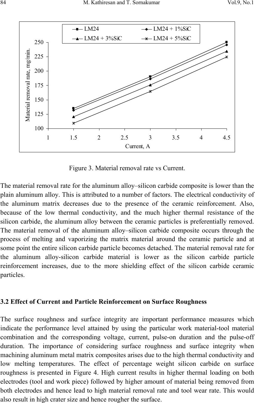 84 M. Kathiresan and T. Sornakumar Vol.9, No.1 100 125 150 175 200 225 250 11.522.533.544.5 Current, A Material removal rate, mg/min. LM24 LM24 + 1%SiC LM24 + 3%SiCLM24 + 5%SiC Figure 3. Material removal rate vs Current. The material removal rate for the aluminum alloy–silicon carbide composite is lower than the plain aluminum alloy. This is attributed to a number of factors. The electrical conductivity of the aluminum matrix decreases due to the presence of the ceramic reinforcement. Also, because of the low thermal conductivity, and the much higher thermal resistance of the silicon carbide, the aluminum alloy between the ceramic particles is preferentially removed. The material removal of the aluminum alloy–silicon carbide composite occurs through the process of melting and vaporizing the matrix material around the ceramic particle and at some point the entire silicon carbide particle becomes detached. The material removal rate for the aluminum alloy-silicon carbide material is lower as the silicon carbide particle reinforcement increases, due to the more shielding effect of the silicon carbide ceramic particles. 3.2 Effect of Current and Particle Reinforcement on Surface Roughness The surface roughness and surface integrity are important performance measures which indicate the performance level attained by using the particular work material-tool material combination and the corresponding voltage, current, pulse-on duration and the pulse-off duration. The importance of considering surface roughness and surface integrity when machining aluminum metal matrix composites arises due to the high thermal conductivity and low melting temperatures. The effect of percentage weight silicon carbide on surface roughness is presented in Figure 4. High current results in higher thermal loading on both electrodes (tool and work piece) followed by higher amount of material being removed from both electrodes and hence lead to high material removal rate and tool wear rate. This would also result in high crater size and hence rougher the surface.  Vol.9, No.1 EDM Studies on Aluminum Alloy-Silicon Carbide Composites 85 6 7 8 9 10 11 12 012345 % Weight SiC Surface roughnes, Micron Current, 1.5ACurrent, 3ACurrent, 4.5A Figure 4. Surface roughness Ra vs Percentage weight silicon carbide. The surfaces obtained for the plain aluminum alloy are rougher than those observed for the aluminum–silicon carbide composite materials machined under the same conditions. The silicon carbide particles shield and protect the aluminum matrix from being removed. This results in less material becoming superheated or molten during the discharge phase. 3.3. Optical Microscopy The optical micrograph of the EDMed surface of the plain LM24 aluminum alloy work piece is presented in Figure 5, 6 and 7. As the pulse current is increased, the deeper craters were most evident and rougher surfaces were more pronounced. This is due to the fact that when pulse current is increased, more intensely discharges strike the surfaces, a great quantity of molten and floating metal suspended in the electrical discharge gap during EDM and resulting in deterioration of the surface roughness.  86 M. Kathiresan and T. Sornakumar Vol.9, No.1 Figure 5. The EDMed surface of plain LM24 aluminum alloy at current of 1.5A. Figure 6. The EDMed surface of plain LM24 aluminum alloy at current of 3A.  Vol.9, No.1 EDM Studies on Aluminum Alloy-Silicon Carbide Composites 87 Figure 7. The EDMed surface of plain LM24 aluminum alloy at current of 4.5A. 4. CONCLUSIONS Aluminum alloy-silicon carbide composites were developed using vortex method and pressure die casting technique. The EDM studies showed that the MRR and the surface roughness are greatly influenced by the current and percent weight silicon carbide. The MRR increases with an i ncrease in the current and decrease in th e percent weight of s ilico n carbide. The surface finish improves with decrease in the current and increase in the percent weight of silicon carbide. REFERENCES [1] Baki Karamıs, M., and Fehmi Nair., 2008, “Effects of reinforcement particle size in MMCs on extrusion die wear”, Wear, Vol.265, pp.1741–1750. [2] Allison, J.E., and Cole, G.S., 1993, “Metal matrix composite in the automotive industry: opportunities and challenges”, JOM, January 1993, pp.19–24. [3] Jose Duarte Marafona and Arlindo Araujo, 2009, “Influence of workpiece hardness on EDM performance”, Int. J. Mach. Tool. Manu., Vol.49, pp.744–748. [4] Karthikeyan, R., Lakshmi Narayanan, P.R., and Naagarazan, R.S., 1999, “Mathematical modelling for electric discharge machining of aluminium–silicon carbide particulate composites”, J. Mater. Process. Tech., Vol.87, pp.59–63.  88 M. Kathiresan and T. Sornakumar Vol.9, No.1 [5] Sushant Dhar, Rajesh Purohit, Nishant Saini, Akhil Sharma and Hemath Kumar, G., 2007, “Mathematical modeling of electric discharge machining of cast Al–4Cu–6Si alloy–10 wt.% SiCP composites”, J. Mater. Process. Tech., Vol.194, pp.24–29 [6] Lloyd, D.J., 1994, “Particle reinforced aluminum and magnesium matrix composite.” Int. Mater. Rev., Vol. 39, pp.1–23. [7] Surappa, M.K., and Rohatgi, P.K., 1981, “Preparation and properties of aluminium alloy ceramic particle composites”, J. Mater. Sci., Vol.16 , pp.983–993 [8] Surappa, M.K., 2003, “Aluminium matrix composites: Challenges and opportunities”, Sadhana, Vol.28, pp.319–334. [9] Sornakumar, T., and Senthilkumar, A., 2008, “Machinability of bronze–alumina composite with tungsten carbide cutting tool insert”, J. Mater. Process. Tech., Vol.202, pp.402–405. [10] Unigovski, Ya.B., and Gutman, E.M., 1999, “Surface morphology of a die-cast Mg alloy”, Appl. Surf. Sci., Vol.153, pp.47–52 [11] Tsoukalas, V.D., 2008, “Optimization of porosity formation in AlSi9Cu3 pressure die castings using genetic algorithm analysis”, Mater. Design, Vol.29, pp.2027–2033. [12] Tharumarajah, A., 2008, “Benchmarking aluminium die casting operations”, Resour. Conserv. Recy., Vol.52, pp.1185–1189. |