Paper Menu >>
Journal Menu >>
 01, 2011-.1, pp1, No.9, Vol. Journal of Minerals & Materials Characterization & Engineering the USA. All rights reserved Printed in jmmce.org 1 Study of Electroslag Remelted and Nitrogen Containing High Speed Tool Steel M41 S. A. El Badry1, Hossam Halfa2, A. Ahmed2*, and A. G. Moustafa1 1Physics department, Faculty of Science, Al-Azhar University, Nasr City, Cairo, Egypt. 2Steel Technology Department, Central Metallurgical Research and Development Institute (CMRDI), Cairo, Egypt *Corresponding Author: azzaazza40@yahoo.com ABSTRACT Mossbauer Effect (ME) spectra, microstructure and hardness of some alloyed and conventional AISI M41 high speed tool steel samples produced by induction furnace as well as after doing electro-slag refining (ESR) process under different slag compositions have been investigated. The obtained ME spectra for all samples could be analyzed to a singlet and three sextets. The appeared singlet in the conventional steel and that alloyed with nitrogen as well as two refined samples using electro-slag remelting 1 and 2 (ESR1, M41N and ESR2, M41N) can be attributed to γ–austenite phase, while the singlet that appeared in the refined sample 3 (ESR3, M41N) can be attributed to some iron nitride of the form ( ε-Fe2N). In the refined sample, which does not contain nitrogen, γ–austenite phase cannot be found and some α-Fe2O3 was detected. The observed three sextets were attributed to three different magnetic martensite phases. It appeared also that some transformations in between the three martensite phases and between martensite and austenite take place, and all these changes were thoroughly discussed. It is interesting to state that the obtained ME results are in agreement with those obtained from optical microscopy and micro-hardness measurements. Key words: High speed tool steel; Nitrogen; ESR; Mossbauer 1. INTRODUCTION Due to its very high hardness, high speed tool steel AISI M41 is usually known as "super hard tool steel materials". The properties of such materials depend mainly on the production technique as well as the refining technology. These two processes are known to affect to a great extent the homogeneity of the alloying elements and the cleanliness of the produced material.  2 S. A. El Badry, Hossam Halfa, A. Ahmed, and A. G. Moustafa Vol.9, No.1 ESR process has a powerful effect on, decreasing the nonmetallic inclusions (NMIs) such as gases and sulphur, soundness, homogeneity and segregation in steel alloys, resulting in improving its mechanical properties [1- 3]. Ghomashichi [4] has shown that a variety of carbides resulted from a eutectic reaction depending on the composition of steel and the cooling rate during solidification process. He reported also that such eutectic carbides in the high speed tool steel are segregated in three different groups, MC, M2C and M6C, where M is the metallic element and C is the carbon atoms. The complex carbides in the high speed tool steel were found to consist of several phases [5], and in addition some inter-metallic compounds such as Fe3W2, Fe3Mo may also appear. It is well known that, nitrogen alloying produces very beneficial effects. It acts usually to produce marked solid solution, which aid the hardening and strengthening of steel [1, 2]. From another point of view, ME spectroscopy can be used now to study the hyperfine structure of many iron compounds, and it can successfully used to reflect the fine changes that take place around iron nuclei in solids [6-8]. Accordingly, this work was subjected to study some nitrogen alloyed and conventional AISI M41 high speed tool steel produced by induction furnace. Also the effect of different slag compositions used in the electro-slag refining processes, on the hyperfine structure changes around the local occupation of iron and their internal magnetic fields were also studied. The optical microscopy and hardness measurements were also applied in this study. 2. EXPERIMENTAL With the objective of this study, a new grade of steel (nitrogen alloyed) comparable to the conventional AISI M41 high speed tool steel has been produced (designed as M41N). The AISI M41 and M41N were electro-slag remelted (ESR) under calcium fluoride (CaF2) based slags. A medium frequency induction furnace (IF) was used to produce the AISI M41 and M41N. The molten metal was casted in form of rods with 75 mm diameter and 120 mm height, where these rods were forged and used as consumable electrodes in ESR process. Such electrodes were electro-slag refined under pre-fused CaF2 based flux with different additions of Al2O3 and CaO. These slags have approximately the same density and different viscosity, interfacial tension and basicities, [see Table 1]. The consumable electrodes and the produced ingots by ESR processes were chemically analyzed and the obtained data were presented in Table 2. Mossbauer Effect (ME) spectroscopy was used to follow the phase change due to ESR and nitrogen alloying of the steel under investigation. The spectra of the studied samples were recorded at room temperature in a transmission geometry using a standard constant acceleration spectrometer. A 25 mCi 57Co radio-active source in Rh matrix was used. The analysis and fitting were carried out relative to a measured ME spectra of a metallic iron foil.  Vol.9, No.1 Study of Electroslag 3 Table 1. Chemical composition and physical properties of the used slags at 1600 oC. Table 2. Chemical composition of consumable electrodes and produced ingots by ESR process. Note: IF = air melted induction furnace heat (free nitrogen). ESR3 = electro-slag remelting (free nitrogen) under slag no. 3. IFN = air melted induction furnace heat (nitrogen containing). ESRN1 = electro-slag remelting (nitrogen containing) under slag no. 1 ESRN2 = electro-slag remelting (nitrogen containing) under slag no. 2. ESRN3 = electro-slag remelting (nitrogen containing) under slag no. 3. Samples from consumable electrodes and ESR ingots were cut off and prepared for microscopic examination. In order to reveal the surface details, the polished surface of the samples are etched with nital 2 % solution. Blocks of dimensions 12 x 12 x 12mm were cut from the investigated steel produced by induction furnace (IF) as well as the electro-slag remelted (ESR) samples. The hardness measurements were carried out on different samples using Indemtec Universal hardness-testing machine with 150 kg working load. For more accuracy three reading were averaged for each sample. 3. RESULT AND DISCUSSION The method of ME spectroscopy was early established to be a sensitive tool for studying the hyperfine structure around iron ions in solids as well as the internal magnetic field of the Slag No. Chemical composition (wt %) CaO / Al2O3 Physical properties CaF2 CaO Al2O3 Density ( g /cm3 ) Viscosity (Poise ) Surface Tension mN/m ESR1 65 15 200.752.5550.433 1375 ESR2 75 15 10 1.5 2.55 0.225 1405 ESR3 55 30 15 2 2.53 0.3 1395 Steel grade process ESR Flux Chemical composition ,(wt%) C Si Mn Cr Mo Co V W P S N M41 IF 0.92 0.43 0.293 4.12 4.25 2.02 2.15 6.53 0.0207 0.0121 0.0045 ESR3 F3 0.925 0.42 0.287 3.981 4.13 2.0 2.08 6.463 0.0221 0.0053 0.0031 M41N IFN 0.9 0.51 0.184 3.785 4.2 2.78 2.18 6.815 0.0226 0.0082 0.135 ESRN1 F1 0.93 0.5 0.176 3.658 4.15 2.99 2.08 6.754 0.0228 0.0061 0.093 ESRN2 F2 0.95 0.49 0.178 3.525 4.025 3.005 2.03 6.54 0.0229 0.008 0.1139 ESRN3 F3 1.1 0.50 0.201 3.645 4.165 2.995 2.18 6.925 0.0244 0.0083 0.1167  4 S. A. El Badry, Hossam Halfa, A. Ahmed, and A. G. Moustafa Vol.9, No.1 ferromagnetic iron compounds. It can reflect also the fine structural changes that take place in the vicinity of iron in solid materials. Therefore, it was applied here to study the hyperfine structure around the different local occupation of iron and the internal magnetic properties of the investigated steel samples nominated in Table 2. Typical ME spectra obtained for the steel samples nominated (IF, M41), (ESR3, M41) and (IF, M41N) are shown in Fig 1. All the obtained spectra appeared to be complex and hence a computer program for analysis and fitting was used to get the hidden sub-spectra. The obtained ME parameters for all the analyzed sub-spectra are presented in Table 3 [isomer shift (IS), quadrupole splitting (QS), line width (LW) and magnetic field intensity (H) as well as the area under the ME absorption peaks of each sub-spectrum (A)]. From the obtained results it can be stated that: a- The spectrum of sample (IF, M41) can be fitted to four sub-spectra, singlet and three sextet. That is, three different magnetic phases together with one non-magnetic phase are present in this sample. b- The spectrum of sample (IF, M41N) appeared to be very close to the spectrum of sample (IF, M41). That is, it composed also of singlet and three sextets, which means that this sample contains also three magnetic phases together with a diamagnetic one. c- The spectrum of sample (ESR3, M41) could be analyzed to a singlet and four sextets. That is, four different magnetic phases together with a non-magnetic one are present in this sample. The obtained hyperfine parameters for each sub-spectrum, the detected sub-spectra indicated that, the non-magnetic phase that appeared in samples (IF, M41) and (IF, M41N) in which the IS value ranges between – 0.19 and – 0.23 mm\s and the QS value equals 0.264 mm\s, can be attributed to a face centered cubic (FCC) γ- austenite. The other three magnetic sites were referred as three different body centered tetragonal (BCT) martensite phases [9, 10]. For simplicity, these phases will be nominated here as MFe1, MFe2 and MFe3. Such phases can be distinguished from one another by the location of the metallic cations or carbon atoms in the solid matrix [11]. Accordingly it can be stated that, the sample (IF, M41) consisted of four different iron bearing phases. A non-magnetic phase having the FCC iron structure and exhibits no internal magnetic field. The other three phases were referred to three magnetic martensite phases, with BCT crystal structure. It was known that martensite structure permits the inclusion of significant amount of carbon atoms at the interstitial vacancies [12]. Therefore, the observed difference in the obtained ME parameters for the three magnetic phases may depend on the location of carbon atoms at the first, the second or higher coordination spheres. In addition to the location of carbon, the substitutional elements (Mn, Cr, Mo, Si …. etc) are soluble in the BCT martensite structure and they strongly disturb the local environment around iron atoms [12, 13]. Thus, the observed three magnetic sub-spectra [MFe1, MFe2 and MFe3] may depend on the location of the carbon atoms and/ or the substitutional elements at the first or the second nearest interstitial sites, and may be further.  Vol.9, No.1 Study of Electroslag 5 Fig. 1. Mossbauer spectra of (IF, M4I), (IF, M4IN) and (ESR3, M4I) samples. Table 3. The hyperfine ME data for the steel (IF, M4I), (IF, M4IN) and (ESR3, M4I) samples. phase IS(mm/s) QS(mm/s) LW(mm/s) HF(kOe) A% IF,M41 MFe1 MFe2 MFe3 γ 0.018 0.026 0.010 -0.193 0.015 0.001 0.0003 0.264 0.30 0.41 0.68 0.39 345 325 291 ----- 16.7 39.4 39.5 4.40 IF,M41N MFe1 MFe2 MFe3 γ 0.021 0.016 0.020 -0.230 0.014 0.0002 -0.007 0.264 0.36 0.41 0.82 0.46 340 320 295 ----- 19.9 28.5 46.1 5.50 ESR3,M41 α-Fe2O3 MFe1 MFe2 MFe3 Fe3C 0.270 0.013 0.059 0.003 0.427 -0.390 0.001 -0.041 0.002 0.545 0.44 0.34 0.36 0.79 0.41 504 342 331 303 ---- 12.1 24.8 10.1 45.0 8.00 -10-50510 Velocity (mm /s) Transmission (%) IF ,M4I N ESR3,M4I IF ,M4 I  6 S. A. El Badry, Hossam Halfa, A. Ahmed, and A. G. Moustafa Vol.9, No.1 According to the internal magnetic field of the three martensite phases and respecting the 34.5 T field intensity value observed for the first sub-spectrum (MFe1), it could be supposed that this phase represent α-Fe phase having relatively comparable amount of Mn. The magnetic interaction between iron and manganese may increase the internal magnetic field of this phase with respect to that of pure α-Fe (33.0 T). The field intensity value of 29.1 T observed for sub- spectrum three (MFe3) could be attributed to some molybdenum atoms appeared in the vacancy of iron. On the other hand, the field intensity value 32.5 T observed for sub-spectrum two (MFe2), may represent an intermediate state between the other two phases [14]. The (IF, M41N) steel sample shows a complex ME spectrum which was fitted also to three sextets and one singlet. According to the ME parameters of the singlet, it could be attributed to γ- austenite phase and it increased by very slight fraction than in sample IF, M41, as seen from Table (3). That is little retained austenite has formed. , which may be due to the fact that, nitrogen was usually considered as austenite stabilizing element [15]. These results are in agreement with the microstructure investigation which indicates that the retained austenite increased in sample (IF, M41N) compared with that in sample (IF, M41) (see Fig .2). The observed changes in the hyperfine magnetic field intensities of the three magnetic phases are comparatively very small. Therefore, it could be supposed that there is no effective rearrangement in the magnetic structure of these phases with respect to that of (IF, M41) steel sample and these slight changes may be due to some rearrangements in the strains that observed through the martensite matrix. The only obvious change was the comparative increase in the martensite MFe3 phase at the expense of the supposed intermediate state MFe2. Sample MFe1 also shows an increase but still very slight. On the other hand, slight variations in the values of IS, QS and LW were detected which could be attributed to a disturbance takes place around iron in the solid matrix. Such disturbance may be due to the transformation in the environment as a result to the introduction of nitrogen, since some substitutional atoms interacted with nitrogen to form some nitrides precipitated in the lattice. This acted to decrease the concentration of the substitutional atoms in the steel matrix. It was detected also by ME that there are slight transformations from one phase to another. All these factors affect relatively the s-electron density of iron and disturb the electric field gradient of the lattice. As the steel sample (IF, M41) was refined to give the sample nominated (ESR3, M41), the obtained ME spectrum appeared to be more complicated. The computer analysis could fit this spectrum to one singlet and four sextets. That is there is one sextet more than that found in the samples (IF, M41) and (IF, M41N). The ME parameters for the singlet were shown to be markedly differ from those obtained for the singlet of samples (IF, M41) and (IF, M41N). The calculated IS and QS values for the singlet of sample (ESR3, M41) were 0.427 and 0.545 mm\s respectively, where these values were found approximately in agreement with those due to a non-magnetic phase in steel [8]. However, such phase was supposed to appear as a result of the refining process and at the same time the previously observed austenite phase disappeared completely. The three martensite phases were still appeared and showed more magnetic field intensities comparable to those appeared in samples (IF, M41) and (IFN, M41). This reflect generally the stability of these phases, but according to the relative ratio of the area under the ME  Vol.9, No.1 Study of Electroslag 7 absorption peaks (for each phase), it can be stated that the highest stable phase was MFe3, since it showed approximately the highest amount among all the detected phases in all samples (Table 3). The observed lower IS and QS values confirm that the refining process act to arrange and to stabilize the solid matrix around iron atoms. Hence the structure becomes somehow compact, which in turn increases the hardness of the solid matrix. These results agree well with the results of the microstructure given in Figure 2 and hardness Table 4. The hardness values verify that ESR technique has a positive effect on the hardness of IF, M41. The improvement in the hardness may be explained by the specific influence of the local solidification time on the phase formation [14]. Electro-slag remelting has the advantage that it has low local solidification time than the conventional casting method. Local solidification time affects not only the phase formation but also the types of carbides and the grain size. So, it helps to form fine grains and fine carbides with higher alloying element and higher carbon content. This was ascertained by the obtained microstructure photos, which clarify that carbides grow longer and thicker and their distribution becomes more uniform in sample (ESR3, M41) comparing to sample (IF, M41). (a) (b) (c) (d) (e) Fig. 2 Microstructure of the investigated steel samples, (a) (IF, M4I), (b) (IF, M4IN), (c) ESR1,M41N, (d) ESR2, M41N, and (e) ESR3 , M41N. 400x.  8 S. A. El Badry, Hossam Halfa, A. Ahmed, and A. G. Moustafa Vol.9, No.1 Table 4. Hardness (HRC) for both M41 and M41N steels. The ME parameters that obtained for the new appeared magnetic phase (forth sextet) was found in agreement with those belongs to α-Fe2O3 [16]. The appearance of such iron oxide phase may be due to the fact that the refining process of metal from inclusion may accompany by secondary contamination by inclusions due to the oxidation of the electrode by atmospheric oxygen, the passage of de-oxidants from slag to metal, etc. Also, the appearance of different iron cations (variable valences) in the slag favors “pumping" of oxygen from atmospheric air into the metal. On the surface of the slag bath, adsorption of oxygen takes place ( 1/2{O2} = (O)ads) , which is attended with ionization of oxygen atoms and oxidation of lower valence cations presented in the slag into those of a higher valence: (O) ads + 2(M2+) +3(O2-) = 2(MO-2) The part of the variable valences of the metal M can be played, for instance, by iron, manganese or titanium. Anions FeO-2, MnO-2 and TiO-2 diffuse through the slag to the metal. Their passage to the metal is accelerated substantially by convective currents in the metal. So, in the process of open air remelting under slag containing iron oxide, the metal can be contaminated by Fe2O3 [16]. The effect of using different slag compositions for refining the nitrogen alloyed steel sample was also investigated. The collected ME spectra for the samples nominated IF, M4IN (without refining), ESR1-M41N, ESR2-M41N and ESR3-M41N (refined) are displayed in Fig. 3. The ME spectra of all these samples can be fitted with a singlet and three sextets nominated γ-austenite, MFe1, MFe2 and MFe3 (as in the first part). The obtained ME parameters for all the detected sub-spectra were presented in Table 5. The observed singlet in samples (IF, M41N), (ESR1- M41N) and (ESR2-M41N) showed negative IS values indicating the presence of paramagnetic γ–austenite phase. The singlet that detected in sample (ESR3-M41N) showed positive IS and high QS values, indicating the presence of some precipitated nitrides of the form ε-Fe2N. These results were found in complete agreement with those obtained by Gontijo et al [17]. Considering the other three magnetic sub-spectra and their ME parameters, it can be supposed that these phases may be due to three different BCT martensite structures. The values of the obtained magnetic field intensities were found to be comparable with those obtained previously on studying samples (IF, M41), (IF, M41N) and (ESR3, M41) as shown in the first part of this study [6-8]. When the area under the ME absorption peaks of each sub-spectra (relative abundance of Steel grade process ESR Flux Hardness(HRC) M41 IF - 44.6 M41N IF - 51.2 ESR1N F1 52.8 ESR2N F2 52.1 ESR3N F3 53.7 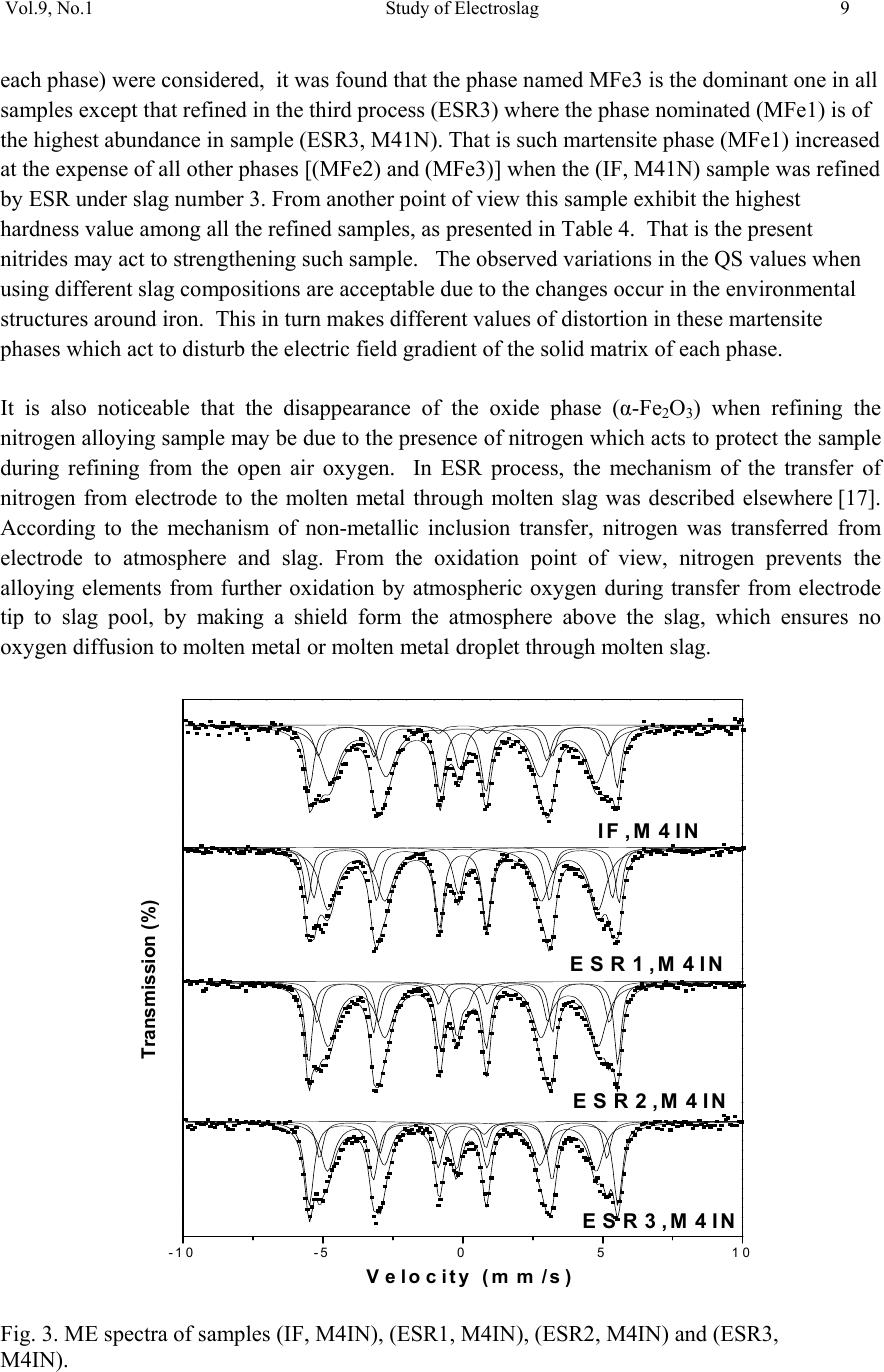 Vol.9, No.1 Study of Electroslag 9 each phase) were considered, it was found that the phase named MFe3 is the dominant one in all samples except that refined in the third process (ESR3) where the phase nominated (MFe1) is of the highest abundance in sample (ESR3, M41N). That is such martensite phase (MFe1) increased at the expense of all other phases [(MFe2) and (MFe3)] when the (IF, M41N) sample was refined by ESR under slag number 3. From another point of view this sample exhibit the highest hardness value among all the refined samples, as presented in Table 4. That is the present nitrides may act to strengthening such sample. The observed variations in the QS values when using different slag compositions are acceptable due to the changes occur in the environmental structures around iron. This in turn makes different values of distortion in these martensite phases which act to disturb the electric field gradient of the solid matrix of each phase. It is also noticeable that the disappearance of the oxide phase (α-Fe2O3) when refining the nitrogen alloying sample may be due to the presence of nitrogen which acts to protect the sample during refining from the open air oxygen. In ESR process, the mechanism of the transfer of nitrogen from electrode to the molten metal through molten slag was described elsewhere [17]. According to the mechanism of non-metallic inclusion transfer, nitrogen was transferred from electrode to atmosphere and slag. From the oxidation point of view, nitrogen prevents the alloying elements from further oxidation by atmospheric oxygen during transfer from electrode tip to slag pool, by making a shield form the atmosphere above the slag, which ensures no oxygen diffusion to molten metal or molten metal droplet through molten slag. Fig. 3. ME spectra of samples (IF, M4IN), (ESR1, M4IN), (ESR2, M4IN) and (ESR3, M4IN). -10 -50510 ESR3,M4IN ESR2,M4IN ESR 1,M4IN IF,M 4IN Transmission (%) Ve loc ity (mm/s ) 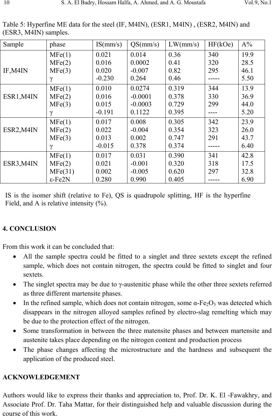 10 S. A. El Badry, Hossam Halfa, A. Ahmed, and A. G. Moustafa Vol.9, No.1 Table 5: Hyperfine ME data for the steel (IF, M4IN), (ESR1, M4IN) , (ESR2, M4IN) and (ESR3, M4IN) samples. 4. CONCLUSION From this work it can be concluded that: • All the sample spectra could be fitted to a singlet and three sextets except the refined sample, which does not contain nitrogen, the spectra could be fitted to singlet and four sextets. • The singlet spectra may be due to γ-austenitic phase while the other three sextets referred as three different martensite phases. • In the refined sample, which does not contain nitrogen, some α-Fe2O3 was detected which disappears in the nitrogen alloyed samples refined by electro-slag remelting which may be due to the protection effect of the nitrogen. • Some transformation in between the three matensite phases and between martensite and austenite takes place depending on the nitrogen content and production process • The phase changes affecting the microstructure and the hardness and subsequent the application of the produced steel. ACKNOWLEDGEMENT Authors would like to express their thanks and appreciation to, Prof. Dr. K. El -Fawakhry, and Associate Prof. Dr. Taha Mattar, for their distinguished help and valuable discussion during the course of this work. Sample phase IS(mm/s) QS(mm/s) LW(mm/s) HF(kOe) A% IF,M4IN MFe(1) MFe(2) MFe(3) γ 0.021 0.016 0.020 -0.230 0.014 0.0002 -0.007 0.264 0.36 0.41 0.82 0.46 340 320 295 ----- 19.9 28.5 46.1 5.50 ESR1,M4IN MFe(1) MFe(2) MFe(3) γ 0.010 0.016 0.015 -0.191 0.0274 -0.0001 -0.0003 0.1122 0.319 0.378 0.729 0.395 344 330 299 ---- 13.9 36.9 44.0 5.20 ESR2,M4IN MFe(1) MFe(2) MFe(3) γ 0.017 0.022 0.013 -0.015 0.008 -0.004 0.002 0.378 0.305 0.354 0.747 0.374 342 323 291 ----- 23.9 26.0 43.7 6.40 ESR3,M4IN MFe(1) MFe(2) MFe(31) ε-Fe2N 0.017 0.021 0.002 0.280 0.031 -0.001 -0.005 0.990 0.390 0.320 0.620 0.405 341 318 297 ----- 42.8 17.5 32.8 6.90 IS is the isomer shift (relative to Fe), QS is quadrupole splitting, HF is the hyperfine Field, and A is relative intensity (%). 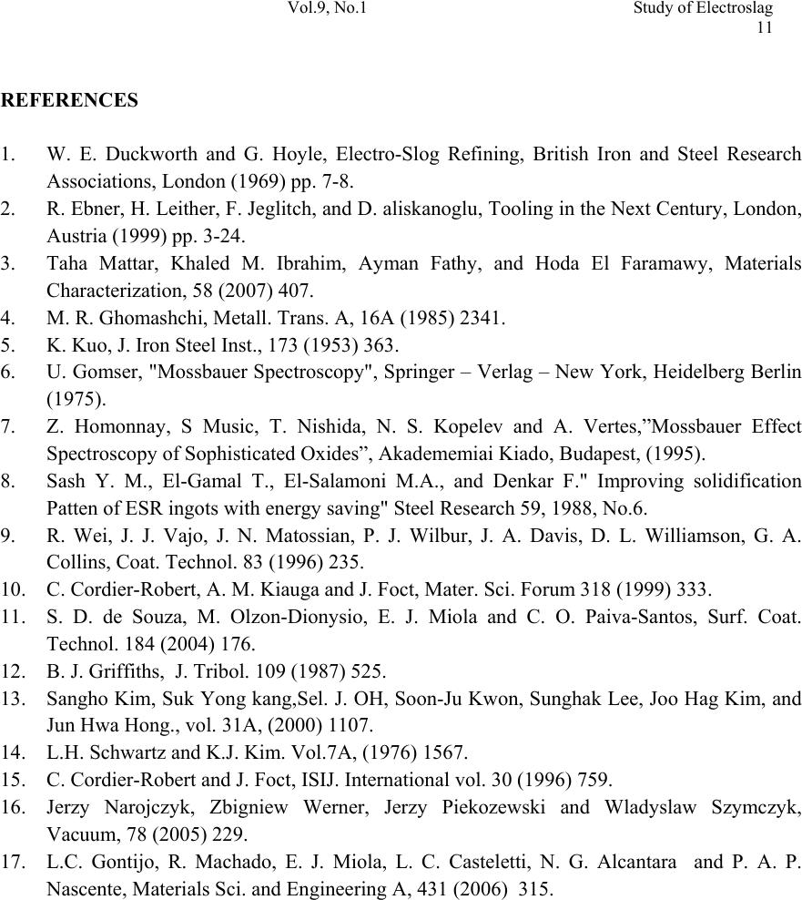 Vol.9, No.1 Study of Electroslag 11 REFERENCES 1. W. E. Duckworth and G. Hoyle, Electro-Slog Refining, British Iron and Steel Research Associations, London (1969) pp. 7-8. 2. R. Ebner, H. Leither, F. Jeglitch, and D. aliskanoglu, Tooling in the Next Century, London, Austria (1999) pp. 3-24. 3. Taha Mattar, Khaled M. Ibrahim, Ayman Fathy, and Hoda El Faramawy, Materials Characterization, 58 (2007) 407. 4. M. R. Ghomashchi, Metall. Trans. A, 16A (1985) 2341. 5. K. Kuo, J. Iron Steel Inst., 173 (1953) 363. 6. U. Gomser, "Mossbauer Spectroscopy", Springer – Verlag – New York, Heidelberg Berlin (1975). 7. Z. Homonnay, S Music, T. Nishida, N. S. Kopelev and A. Vertes,”Mossbauer Effect Spectroscopy of Sophisticated Oxides”, Akadememiai Kiado, Budapest, (1995). 8. Sash Y. M., El-Gamal T., El-Salamoni M.A., and Denkar F." Improving solidification Patten of ESR ingots with energy saving" Steel Research 59, 1988, No.6. 9. R. Wei, J. J. Vajo, J. N. Matossian, P. J. Wilbur, J. A. Davis, D. L. Williamson, G. A. Collins, Coat. Technol. 83 (1996) 235. 10. C. Cordier-Robert, A. M. Kiauga and J. Foct, Mater. Sci. Forum 318 (1999) 333. 11. S. D. de Souza, M. Olzon-Dionysio, E. J. Miola and C. O. Paiva-Santos, Surf. Coat. Technol. 184 (2004) 176. 12. B. J. Griffiths, J. Tribol. 109 (1987) 525. 13. Sangho Kim, Suk Yong kang,Sel. J. OH, Soon-Ju Kwon, Sunghak Lee, Joo Hag Kim, and Jun Hwa Hong., vol. 31A, (2000) 1107. 14. L.H. Schwartz and K.J. Kim. Vol.7A, (1976) 1567. 15. C. Cordier-Robert and J. Foct, ISIJ. International vol. 30 (1996) 759. 16. Jerzy Narojczyk, Zbigniew Werner, Jerzy Piekozewski and Wladyslaw Szymczyk, Vacuum, 78 (2005) 229. 17. L.C. Gontijo, R. Machado, E. J. Miola, L. C. Casteletti, N. G. Alcantara and P. A. P. Nascente, Materials Sci. and Engineering A, 431 (2006) 315. |

