Paper Menu >>
Journal Menu >>
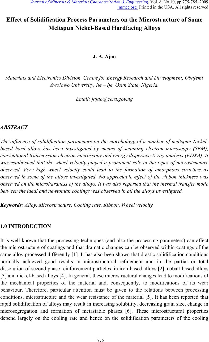 Journal of Minerals & Materials Characterization & Engineering, Vol. 8, No.10, pp.775-785, 2009 jmmce.org Printed in the USA. All rights reserved 775 Effect of Solidification Process Parameters on the Microstructure of Some Meltspun Nickel-Based Hardfacing Alloys J. A. Ajao Materials and Electronics Division, Centre for Energy Research and Development, Obafemi Awolowo University, Ile – Ife, Osun State, Nigeria. Email: jajao@cerd.gov.ng ABSTRACT The influence of solidification parameters on the morphology of a number of meltspun Nickel- based hard alloys has been investigated by means of scanning electron microscopy (SEM), conventional transmission electron microscopy and energ y dispersive X-ray analysis (EDXA). It was established that the wheel velocity played a prominent role in the types of microstructure observed. Very high wheel velocity could lead to the formation of amorphous structure as observed in some of the alloys investigated. No appreciable effect of the ribbon thickness was observed on the microhardness of the a lloys. It was also repo rted that the thermal transfer mod e between the ideal and newtonian coolings was observed in all the alloys investigated. Keywords: Alloy, Microstructure, Cooling rate, Ribbon, Wheel velocity 1.0 INTRODUCTION It is well known that the processing techniques (and also the processing parameters) can affect the microstructure of coatings and that dramatic changes can be observed within coatings of the same alloy processed differently [1]. It has also been shown that drastic solidification conditions normally achieved good results in microstructural refinement and in the partial or total dissolution of second phase reinforcement particles, in iron-based alloys [2], cobalt-based alloys [3] and nickel-based alloys [4]. In general, these microstructural changes lead to modifications of the mechanical properties of the material and, consequently, to modifications of its wear behaviour. Therefore, particular attention must be given to the relations between processing conditions, microstructure and the wear resistance of the material [5]. It has been reported that rapid solidification of alloys may result in increasing solubility, decreasing grain size, change in microsegregation and formation of metastable phases [6]. These microstructural properties depend largely on the cooling rate and hence on the solidification parameters of the cooling  776 J. A. AjaoVol.8, No.10 techniques. For meltspinning technique, a change in the microstructure may be expected even within the same ribbon considering the decrease in the solidification rate from the wheel contact side to the free surface of the ribbon [7]. Rapid solidification by meltspinning technique has been applied to a variety of new materials [8, 9]. Cooling rate measurements during this technique have given some insight into the ribbon formation mechanisms and the development of microstructure features [10, 11]. Nickel-based hard alloys have a unique combination of properties that enables them to be used in a variety of special purpose applications especially in the automobile, pharmaceutical, petrochemical etc industries to enhance resistance to wear and corrosion which are some of the major problems facing these industries. The Ni–Cr–B–Si–C colmonoy alloys provide adhesive wear and corrosion resistance at ambient and high temperatures. The NiCrBSi coatings are widely employed to improve the quality of components whose surface is subjected to severe tribological conditions such as coal-fired boilers, heat exchangers, turbines, tools, extruders, plungers, rolls for rolling mills, agriculture machinery, etc. [12]. They exhibit excellent resistance to abrasive wear because of the boride and carbide dispersions within their microstructures. These alloys are usually applied in the form of thick protective coatings which lead to improved tool life and performance. Hence in the present study, the influence of some process parameters on the phase formations and transformations in some of these nickel-based hard alloys employed as surface coatings were investigated after rapid solidification by meltspinning. 2.0 EXPERIMENTAL PROCEDURE 2.1 Production of Meltspun Ribbon The nominal composition of the alloys investigated is presented in Table 1. Table 1: Nominal compositions of the alloys in weight percent. Alloys B C Si Cr W Ni NBT1 16.2 - - - - 83.8 NBT2 4.7 6.00 1.90 28.40 3.40 55.60 NBT3 4.9 4.75 5.85 27.90 0.03 56.57 The ribbons of the alloys were produced by the rapid solidification technique of meltspinning. This technique consists of induction-melting the accurately weighed mixtures of the alloys in a crucible with a nozzle of diameter 0.8mm through which the molten alloys is ejected onto a rotating cooled copper wheel under an ambient pressure of about 200mbar helium. The temperature of the liquid alloy before ejection onto the rotating copper wheel is kept at about 500C above the melting point to ensure complete homogenisation of the molten alloy. The wheel surface velocity used in this work varied from 15 to 45m.s-1. The ribbons formed after cooling were 1 to 2mm wide and 20 to 50µm thick. The cooling rate was estimated between 2 and 5x10⁵K.s-1. The value of the heat transfer coefficient (h) between the melt and the copper substrate of 105WK-1m-2 which corresponds to newtonian thermal transfer has been previously  Vol.8, No.10 Effect of Solidification Process Parameters 777 calculated for this apparatus [13]. The summary of the process parameters used for the optimisation of the ribbon quality is shown in Table 2. Table 2: Solidification process parameters for the meltspun ribbons. Wheel material Cu - Cr Nozzle 0.8mm Melt temperature (K) 1343 – 1493K Wheel surface speed (m.s-1) 15 - 45 Ejection pressure (mbar) 200 Nozzle – wheel – gap (mm) 2 - 5 Melt weight (g) 10 - 15 2.2 Characterization of the Ribbons The solidification structure of the ribbons was investigated by scanning electron microscope (SEM – JSM35) equipped with energy dispersive X-ray analysis system (EDX – TRACOR), transmission electron microscope (TEM), and X – ray diffraction (XRD). The samples for SEM observations were slightly etched with an etchant consisting of 5g FeCl3 +10ml HCl dissolved in 50ml H2O while thin foils for TEM were electrolytically thinned in an electrolyte containing 9:1 acetic – perchloric solution at room temperature under 15V. The samples for TEM were examined in a direction vertical to the foil surface. Some thin foils were prepared by ion bombardment to reduce the level of contamination of the samples. 3.0 RESULTS AND DISCUSSION 3.1 Solidification structure and the cooling rate A variety of microstructure was observed in the alloys investigated depending on the nominal composition of the alloys and the cooling rates. 3.1.1 Cross – sectional view of the meltspun ribbon The transversal cross – section of the ribbon of NBT1 alloy is shown in the scanning electron micrograph of Fig. 1a. In this figure, three zones can be distinguished. On the wheel side of the ribbon, a crystalline structure was observed followed by a columnar structure. The third zone at the free wheel side of the ribbon is a dendrite structure. The columnar grains are inclined at an angle of typically 5 to 150 towards the spin direction. The triplex microstructure that occurs in these alloys is the result of the varying cooling rates through the thickness of the material as it solidified from the bottom to the top.  778 J. A. AjaoVol.8, No.10 Figure 1: (a) The scanning electron micrograph of the transversal cross – section of the ribbon of alloy NBT1. Transmission electron micrographs of the same alloy at different wheel velocities: (b) Vr = 15m.s-1 (c) Vr= 28m.s-1 (d) Vr= 45m.s-1. 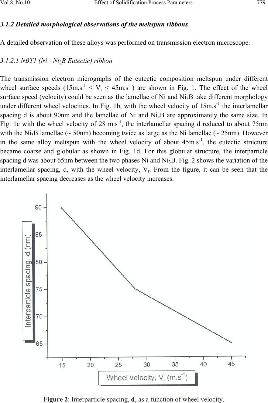 Vol.8, No.10 Effect of Solidification Process Parameters 779 3.1.2 Detailed morphological observations of the meltspun ribbons A detailed observation of these alloys was performed on transmission electron microscope. 3.1.2.1 NBT1 (Ni - Ni3B Eutectic) ribbon The transmission electron micrographs of the eutectic composition meltspun under different wheel surface speeds (15m.s-1 < Vr < 45m.s-1) are shown in Fig. 1. The effect of the wheel surface speed (velocity) could be seen as the lamellae of Ni and Ni3B take different morphology under different wheel velocities. In Fig. 1b, with the wheel velocity of 15m.s-1 the interlamellar spacing d is about 90nm and the lamellae of Ni and Ni3B are approximately the same size. In Fig. 1c with the wheel velocity of 28 m.s-1, the interlamellar spacing d reduced to about 75nm with the Ni3B lamellae (~ 50nm) becoming twice as large as the Ni lamellae (~ 25nm). However in the same alloy meltspun with the wheel velocity of about 45m.s-1, the eutectic structure became coarse and globular as shown in Fig. 1d. For this globular structure, the interparticle spacing d was about 65nm between the two phases Ni and Ni3B. Fig. 2 shows the variation of the interlamellar spacing, d, with the wheel velocity, Vr. From the figure, it can be seen that the interlamellar spacing decreases as the wheel velocity increases. Figure 2: Interparticle spacing, d, as a function of wheel velocity.  780 J. A. AjaoVol.8, No.10 3.1.2.2 NBT2 and NBT3 Alloys Unlike the NBT1 alloy, the microstructure of the ribbon of the other two alloys (NBT2 and NBT3) containing various metallic and non metallic additions is not homogeneous. This is probably partly due to the complex composition of the alloys and partly due to gas trapping between the ribbon and the wheel. This made a direct correlation between the microstructure and the cooling rate very difficult. It is understood that the diffusion-controlled processes proceeded very rapidly; hence the final microstructure was not influenced by cooling rate alone. Fig. 3a shows the transmission electron micrograph observed in alloy NBT2 after meltspinning with a wheel velocity of 28m.s-1. The microstructure is complex. However, from the EDX analyses performed on the alloy, three major phases could be identified namely: (i) a phase (marked 1) with cubic structure (dark in bright field) rich in chromium. The EDX analysis is shown in Fig. 3b. From the EDXA, the composition of this phase approaches that of M23C6 metastable phase. The formation of cubic metastable phases has been observed in different ternary systems such as Fe-Ni-B [14] or Ni-B-Si [15]. This carbide phase has been reported to be a brittle phase [16]. (ii) a phase (marked 2) bright in bright field and particularly rich in nickel, chromium and tungsten (Fig. 3c). The composition of this phase approaches that of M2W. (iii) a third phase (marked 3) very rich in nickel is the Ni (α) solid solution as depicted by Fig. 3d. The chromium-to-nickel ratio obtained by EDXA of around 0.48 is in good agreement with the global composition of the alloy (chromium-to-nickel ratio, 0.50). In the case of NBT3 alloy with nominal composition similar to that of alloy NBT2, two distinct zones were observed – an amorphous zone (marked A) and a microcrystalline zone (marked C) (Fig. 4a). The EDXA performed on the microcrystalline zone showed the presence of aggregates of crystals of about 100Å in size consisting of nickel, chromium and tungsten (Fig. 4b). The diffraction pattern (Fig. 4c) obtained on the amorphous zone (marked A) showed effectively the existence of this zone. It should be noted from our observations that the high silicon content (5.85wt%) in this alloy NBT3 compared to 1.90wt% in NBT2 alloy seemed to play an important role in the amorphization of this alloy. High silicon content promotes glass formation in these complex alloys. This is in agreement with reported work on the Ni-B-Si system where silicon additions increased the composition range where glasses can be formed [17]. Furthermore, the microstructure observations of the above alloy meltspun at lower wheel velocity (Vr ~ 15m.s-1) showed that the whole alloy became microcrystallized. No amorphous zone was observed.  Vol.8, No.10 Effect of Solidification Process Parameters 781 Figure 3: (a) Transmission electron micrograph observed in the ribbon of alloyNBT2 at wheel velocity of 28m.s-1. EDX analysis on (b) M23C6 metastable phase (c) M2W phase (d) Ni (α) solid solution. A general relationship has been proposed between the cooling rate, T, and the wheel velocity, Vr, by Cantor [11]: T ≈ 1.2x10⁴ Vr From the above relationship, the cooling rate in our experiments could be estimated between 2 and 5x10⁵K.s-1 for wheel velocities of 15m.s-1 < Vr < 45m.s-1.  782 J. A. AjaoVol.8, No.10 Figure 4: (a) Transmission electron micrograph observed in alloy NBT3 after meltspinning with a wheel velocity of 28m.s-1 depicting two zones – amorphous (A) and microcrystalline (C) (b) EDX analysis on the microcrystalline zone (c) diffraction pattern on the amorphous zone. 3.2 Wheel velocity and the ribbon thickness A number of relations [18, 19] have been proposed in order to calculate and relate the solidification parameters such as (i) cooling rate T and (ii) the propagation rate of the solid – ENERGY ( keV )  Vol.8, No.10 Effect of Solidification Process Parameters 783 liquid interface, V, from accessible experimental factors such as the wheel velocity, Vr, and the ribbon thickness, e. Hillmann and Hilzinger [18] in their work on the Fe40Ni40P14B6 alloy proposed the following relationship between the ribbon thickness, e and the wheel velocity Vr: e ≈ Vr-α where α ~ 0.75 and 1.75 for ideal and newtonian coolings respectively. Experimentally, these authors have reported α ~ 0.80 indicating a mixed regime. In the same vein, Kavesh [19] and Lieberman and Graham [20] reported a slightly higher value (α ~ 0.83). A similar calculation in this present work gives a value of approximately 1.03 for α. This value of α indicates a thermal transfer mode intermediate between the ideal and newtonian coolings. 3.3 Micro-Hardness The ribbons were subjected to Vicker’s hardness tests. Fig. 5 shows the microhardness of the meltspun ribbons as a function of the ribbon thickness. Figure 5: Variation of microhardness as a function of the ribbon thickness From the figure, the hardness of the ribbon decreased as the ribbon thickness increased. This strange behaviour can be explained by the localized segregations of the hard phases such as M23C6, M2W etc. As reported earlier, different zones were observed in these alloys thereby giving rise to non uniform hardness of the ribbons. But Vogt and Frommeyer [21] reported a microhardness weakly influenced by the ribbon thickness in the Fe – 3.2wt%C alloys. 4. CONCLUSION The influence of solidification parameters on some meltspun Nickel hard alloys has been investigated with regard to their effects on the ribbon castability as well as on ribbon microstructure. It has been established that the microstructure varied substantially with the wheel velocity. In complex alloys (NBT2 and NBT3), depending on the wheel velocity, amorphous or  784 J. A. AjaoVol.8, No.10 microcrystalline structure was observed with the formation in microcrystallized samples of metastable phases such as M23C6. At intermediate wheel velocity, a mixture of both amorphous and microcrystalline phases was reported. Interestingly, it was also established that the microhardness decreased as the ribbon thickness increased. ACKNOWLEDGEMENTS The author is indebted to Dr. M. Kemell for assistance in electron microscopy and to Centre for Energy Research and Development, Obafemi Awolowo University, Ile-Ife, Nigeria for granting him leave of absence during the preparation of this work. REFERENCES [1] Navas, C, Colaço, R, de Damborenea, J, and Vilar, R, 2006, “Abrasive wear behaviour of laser clad and flame sprayed-melted NiCrBSi coatings”, Surface & Coatings Technology, Vol.200, pp. 6854–6862. [2] Conde, A, Zubiri, F and de Damborenea, J, 2002, “Cladding of NiCrBSi coatings with a high power diode laser”, Mater. Sci. Eng. A Vol. 334 pp. 233–238. [3] Rodr´ıguez, J, Mart´ın, A, Fernández, R and Fernández, J. E, 2003, “An experimental study of the wear performance of NiCrBSi thermal spray coatings”, Wear Vol. 255 pp. 950–955. [4]Li, Q, Zhang, D, Lei, T, Chen, C and Chen, W, 2001, “Comparison of laser-clad and furnace- melted Ni-based alloy microstructures”, Surf. Coat. Technol. Vol. 137 pp. 122–135. [5] Stachowiak, G and Batchelor, A. W, Engineering Tribology, Elsevier, 2000, p.433. [6] Emmerich, K, 1985, in “Ribbon formation of roller cast Al-Cu” Rapidly Quenched Metals, eds. S. Steeb, H. Warlimont (eds.) pp. 71-74. [7] Gonz´alez, R, Garc´ıa, M. A, Pe˜nuelas, I, Cadenas, M, Roc´ıo Fern´andez, Ma, Hern´andez Battez, A and Felgueroso, D, 2007, “Microstructural study of NiCrBSi coatings obtained by different processes” Wear Vol. 263 pp. 619–624. [8] Remy, A, and Frantz, C, 1987, “Microstructure types de rubans en acier elabores par refroidissement rapide sur substrat rotatif” Mem. Et. Sci. Rev. Met, Mai 1987, pp. 265-274. [9] Huang, S. C and Chang, K. M, 1984, “Effects of boron addition on a meltspun Ni-base superalloy”, J. Mat. Sci. Vol. 19, pp. 1220-1228. [10] Lebaili, S, Ajao, J and Hamar-Thibault, S, 1992, “Preparation and Characterization of meltspun nickel-based alloys containing heavy metals”, J. Alloys and Compd., Vol. 188, pp. 87- 93. [11] Cantor, B, 1985, Proc. of the NATO Advanced Research Workshop on Rapid Solidification P. R. Sahm (ed.) Netherlands, (1985) pp. 3-28. [12] Tylezak, J. H and Oregon, A, 1995, Friction, Lubrication and Wear Technology, ASM Handbook, vol. 18, p. 184. [13] Casanova, P, Joud, J. C, Senillou, C, and Yavari, A. R, 1984, ”Elaboration des rubans larges de verres metaliques” Mem. Et. Sci. Rev. Met. Vol. 81, pp. 553-559. [14] Koster, U, 1982, “Influence of solidification parameters on the microstructure of rapidly quenched Fe-Ni-B alloys”, in Rapidly Solidified Amorphous and Crystalline Alloys, B. H. Kear, B. C. Giessen and M. Cohen (eds.), North-Holland, Amsterdam, p. 179.  Vol.8, No.10 Effect of Solidification Process Parameters 785 [15] Morris, D. G, 1985, “Crystallization embrittlement of Ni-Si-B alloys”, J. Mat. Sci. Vol. 20, pp. 331-340 [16] Stadelmaier, H. H and Fraker, A. C, 1962, “The Nickel- Aluminum- Boron ternary system” Metall Vol. 16, pp.212-217. [17] Hamar-Thibault, S, Ajao, J, Lebaili, S, 1991, “Segregation in Some Nickel-Based Hardfacing Alloys Prepared by Melt-Spinning” Proc. 4th Eurpean Conf. On Applications of Surface and Interface Analysis, Budapest 1991, Hungary, p. 391-394. [18] Hillman, H, and Hilzinger, R. R, 1978, “On the formation of amorphous ribbons by the meltspin technique” Rapidly Quenched Metals; Metals Society London pp. 22-29. [19] Kavesh, S, 1984, Rapidly Solidified Metastable Materials, ed. B. H. Kear, B. C. Giessen, North Holland p. 165. [20] Liebermann, H. H and Graham, C. D, 1976, IEEE Trans. on Magnetics, Vol. 12, pp. 291- 298. [21] Vogt, E and Frommeyer, O, 1987, “Solidification Parameters and Microstructures of Rapidly Solidified Fe-Si and Fe-C Meltspun Ribbons”, Z. Metallkde, Vol. 78, pp. 262-267. |