Paper Menu >>
Journal Menu >>
 Journal of Minerals & Materials Characterization & Engineering, Vol. 8, No.5, pp 379-391, 2009 jmmce.org Printed in the USA. All rights reserved Effect of Filler Materials on Dry Sliding Wear Behavior of Polymer Matrix Composites – A Taguchi Approach S. Basavarajappa 1 , K.V. Arun 2* , J. Paulo Davim 3 1 Department of studies in Mechanical Engineering, University BDT College of Engineering, Davangere-577004, India 2 Department of studies in Industrial & Production Engineering, University BDT College of Engineering, Davangere-577004, India 3 Department of Mechanical Engineering, University of Aveiro, Campus Santiago, 3810-193 Aveiro, Portugal *Corresponding Author: bdt.arun@gmail.com ABSTRACT The tribological behaviour of glass epoxy polymer composites with SiC and Graphite particles as secondary fillers was studied using a pin-on-disc wear rig under dry sliding conditions. The influence of wear parameters like, applied load, sliding speed, sliding distance and percentage of secondary fillers, on the wear rate were investigated. A plan of experiments, based on the techniques of Taguchi, was performed to acquire data in a controlled way. An orthogonal array and analysis of variance (ANOVA) were employed to investigate the influence of process parameters on the wear of these composites. The results showed that the inclusion of SiC and Graphite as filler materials in glass epoxy composites will increase the wear resistance of the composite greatly. Key Words: Polymer matrix composites, Fillers, Taguchi Technique, Orthagonal Array, Wear. 1. INTRODUCTION Fabric reinforced polymeric composites have gained acceptance for use in many industries including aerospace, automotive, marine, infrastructure, and recently oil and gas. Polymers and their composites are being increasingly employed in view of their good strengths and low densities. Besides, a wider choice of materials and ease of manufacturing make them ideal for many engineering applications [1–3]. On account of their good combination of properties, fibre- reinforced polymer composites are used particularly in the automotive and aircraft industries, the manufacturing of spaceships and sea vehicles [3–5]. There are two main characteristics which make these materials attractive compared with conventional metallic systems. They are relatively  380 S. Basavarajappa, K. V. Arun, J. Paulo Davim Vol.8, No.5 low density and ability to be tailored to have stacking sequences that provide high strength and stiffness in directions of high loading [6]. Composite materials consist of resin and a reinforcement chosen according to the desired mechanical properties and the application [4, 7, 8]. Many studies reported that the wear resistance with polymer sliding against steel improved when the polymers are reinforced with glass or aramid fibres. However, the behaviour is affected by factors, such as the type, amount, size, shape and orientation of the fibres, the matrix composition and the test conditions, such as load, speed and temperature [4, 5, 9]. Reports of application of polymer and its composites in mechanical components such as gears, cams, wheels, impellers are cited in literature [10]. It is generally known that the epoxy resins with appropriate curing agents find use as products in protective coatings, adhesives, structural components etc. This is mainly because of their good mechanical properties, excellent chemical resistance, good wettability and electrical characteristics. When these epoxy resins are reinforced with high strength glass fibres, the resulting product find many structural applications. Besides this, the resins have low coefficient of friction and thermal expansion as well as higher load bearing capability compared to some thermoplastics. The applications on these materials, to meet the present demands can be achieved by the introduction of fillers into these polymeric systems having fibrous reinforcement. The modification of the tribological behavior of polymers by the addition of filler materials has shown a great promise and so has lately been a subject of considerable interest. The filler materials include organic, inorganic, and metallic particulate materials in both macro and nano sizes. Most studies on filler action in the case of polymer composites sliding against metal counter faces have focused on the reduction of wear rate and the coefficient of friction. This would enable the user to have optimum wear rate and coefficient of friction. However, the use of these filler based materials in actual service requires a careful cataloguing of the processing conditions employed and the attendant structure that follows. An approach of this kind would enable a correlation between structure and wear behaviour to emerge. G–E (Glass-Epoxy) system having fillers, as earlier studies on epoxy resins without fibrous reinforcement, but containing inclusion of fillers showed a promise for venturing into such a [11] programme . The fillers chosen to go with G–E system were oxide in one case and rubber in the other. The selection of these were based on studying the influence of the presence of an elastomeric substance well known for property like stretchability, vis-a-vis an oxide known for its non- deforming nature and ability to sustain load as well as temperature raise due to friction during sliding wear. The two materials are thus expected to respond quite differently when subjected to dry sliding wear, where compressive and frictional forces dominate.Nanometer SiC, micron SiC, and whisker SiC were used as fillers in polyetheretherketonc (PEEK) and the influence of these  Vol.8, No.5 Effect of Filler Materials on Dry Sliding Wear Behavior of Polymer Matrix Composites 381 fillers on the friction and wear of the PEEK composites was studied [12] and an effective reduction in the friction and wear has been achieved in the PEEK with Nanometer SiC as a filler. Suresha et al [13] carried out friction and wear behavior on FRP materials. Authors have compared the carbon epoxy (C-E) composite with that of glass epoxy (G-E) composites for tribological properties using a pin on disc set up. The tests are conducted by subjecting G-E & C- E samples sliding against a hard steel disc (62 HRc) under different sliding and loading conditions. It was found that, for optimization of tribological characteristics, moderate load and sliding velocity are the preferred choice irrespective of the type of the composite used. Basavarajappa et al [14] undertook an extensive work on dry sliding wear behavior of metal matrix composites. In their study and discussion, the effect of reinforcement, sliding distance, applied load, sliding speed that influence the dry sliding wear behavior of this group of composites were examined in detail. The design of experimental approach by Taguchi method enabled to analyze successfully the friction and wear behavior of composites with filler material, sliding speed, sliding distance and load as the variables with fewer experiments. Keeping these aspects in mind, it was decided to study the dry slide wear characteristics of glass fibre epoxy composite with secondary fillers. The present investigation focuses on the dry sliding wear characteristics of a glass-epoxy composite, filled with particulate SiCp and graphite particles. A plan of experiments, to acquire the data in a controlled has been designed on the basis of Taguchi technique. 2. TAGUCHI TECHNIQUE Taguchi technique is a powerful tool for the design of high quality systems [15-17]. The Taguchi approach to experimentation provides an orderly way to collect, analyze, and interpret data to satisfy the objectives of the study. By using these methods, in the design of experiments, one can obtain the maximum amount of information for the amount of experimentation used. Taguchi parameter design can optimize the performance characteristics through the setting of design parameters and reduce the sensitivity of the system performance to the source of variation [17- 18]. This is accomplished by the efficient use of experimental runs to the combinations of variables studied. This technique is a powerful tool for acquiring the data in a controlled way and to analyze the influence of process variable over some specific variable, which is unknown function of these process variables. The most important stage in the plan of experiments is selection of factors. Taguchi technique creates a standard orthogonal array to accommodate the effect of several factors on the target value and defines the plan of experiments. The experimental results are analyzed using analysis of means and variance to study the influence of factors.  382 S. Basavarajappa, K. V. Arun, J. Paulo Davim Vol.8, No.5 3. MATERIALS AND METHODS 3.1. Specimen Fabrication Epoxy resin was used as the matrix material in the present work. L12 epoxy resin with K6 grade room temperature curing hardener was employed for the matrix material. This matrix was chosen, since it provides good resistance to alkalis and good adhesive properties owing to the cross-linking chain between the resin and the hardener. An 8 mil plain weave bi-directional fabric with epoxy compatible finish was used as the reinforcement. The SiCp and Graphite (Supplied by Madras Metallurgical Pvt. Ltd) particles that have passed through 400 mesh sieve ware used as fillers. The composition and the volume fractions of the matrix, reinforcement and the secondary fillers has been shown in Table 1. Table 1 Composition and volume fraction of the SiCp and Graphite in the Glass Epoxy composites Designation Volume fraction Epoxy Glass Fabric SiCp Graphite Type I 40 60 -- -- Type II 40 50 10 -- Type III 40 40 10 10 The hand lay up technique was used to fabricate the composite. The laminate was cured at ambient conditions for a period of about 24 hrs. The cured composite laminate was cut using a diamond tipped cutter to yield wear test, the samples of size 6mm x 6mm x 3mm. 3.2. Test Set Up and Wear Runs A pin-on-disc test apparatus [19] was used to investigate the dry sliding wear characteristics of the composites as per ASTM G99-95 standards. The disc used is En-32 steel hardened to 62 HRC, 120mm track diameter and 8mm thick, with surface roughness of 10µm Ra. The tests were conducted by selecting test duration, load and velocity and performed in a track of 115mm diameter. The glass fabric layers in the composites are parallel to the contact surface and to the sliding direction. The surface (6mmX6mm) of the composites specimen makes contact to the counter surface. Prior to testing, the samples are rubbed over a 600 grade SiC paper to ensure proper contact with the counter surface. The surface of both the samples and disc are cleaned with a soft paper soaked in acetone before the test. The test set up used for the experimentation is as shown in the Figure 1. 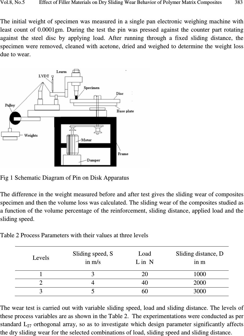 Vol.8, No.5 Effect of Filler Materials on Dry Sliding Wear Behavior of Polymer Matrix Composites 383 The initial weight of specimen was measured in a single pan electronic weighing machine with least count of 0.0001gm. During the test the pin was pressed against the counter part rotating against the steel disc by applying load. After running through a fixed sliding distance, the specimen were removed, cleaned with acetone, dried and weighed to determine the weight loss due to wear. Fig 1 Schematic Diagram of Pin on Disk Apparatus The difference in the weight measured before and after test gives the sliding wear of composites specimen and then the volume loss was calculated. The sliding wear of the composites studied as a function of the volume percentage of the reinforcement, sliding distance, applied load and the sliding speed. Table 2 Process Parameters with their values at three levels Levels Sliding speed, S in m/s Load L in N Sliding distance, D in m 1 3 20 1000 2 4 40 2000 3 5 60 3000 The wear test is carried out with variable sliding speed, load and sliding distance. The levels of these process variables are as shown in the Table 2. The experimentations were conducted as per standard L 27 orthogonal array, so as to investigate which design parameter significantly affects the dry sliding wear for the selected combinations of load, sliding speed and sliding distance. 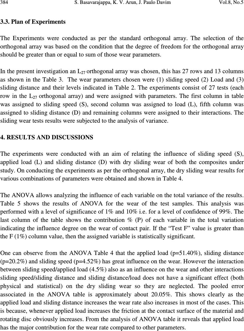 384 S. Basavarajappa, K. V. Arun, J. Paulo Davim Vol.8, No.5 3.3. Plan of Experiments The Experiments were conducted as per the standard orthogonal array. The selection of the orthogonal array was based on the condition that the degree of freedom for the orthogonal array should be greater than or equal to sum of those wear parameters. In the present investigation an L 27 orthogonal array was chosen, this has 27 rows and 13 columns as shown in the Table 3. The wear parameters chosen were (1) sliding speed (2) Load and (3) sliding distance and their levels indicated in Table 2. The experiments consist of 27 tests (each row in the L 27 orthogonal array) and were assigned with parameters. The first column in table was assigned to sliding speed (S), second column was assigned to load (L), fifth column was assigned to sliding distance (D) and remaining columns were assigned to their interactions. The sliding wear tests results were subjected to the analysis of variance. 4. RESULTS AND DISCUSSIONS The experiments were conducted with an aim of relating the influence of sliding speed (S), applied load (L) and sliding distance (D) with dry sliding wear of both the composites under study. On conducting the experiments as per the orthogonal array, the dry sliding wear results for various combinations of parameters were obtained and shown in Table 4. The ANOVA allows analyzing the influence of each variable on the total variance of the results. Table 5 shows the results of ANOVA for the wear of the test samples. This analysis was performed with a level of significance of 1% and 10% i.e. for a level of confidence of 99%. The last column of the table shows the contribution % (P) of each variable in the total variation indicating the influence degree on the wear of contact pair. If the “Test F” value is greater than the F (1%) column value, then the assigned variable is statistically significant. One can observe from the ANOVA Table 4 that the applied load (p=51.40%), sliding distance (p=20.2%) and sliding speed (p=4.52%) has great influence on the wear. However the interaction between sliding speed/applied load (4.5%) also as an influence on the wear and other interactions sliding speed/sliding distance and sliding distance/load does not have a significant effect (both physical and statistical) on the dry sliding wear so they are neglected. The pooled error associated in the ANOVA table is approximately about 20.05%. This shows clearly as the applied load and sliding distance increases the wear rate also increases in most of the cases. This is because, whenever applied load increases the friction at the contact surface of the material and rotating disc obviously increases. From the analysis of ANOVA table it reveals that applied load has the major contribution for the wear rate compared to other parameters. 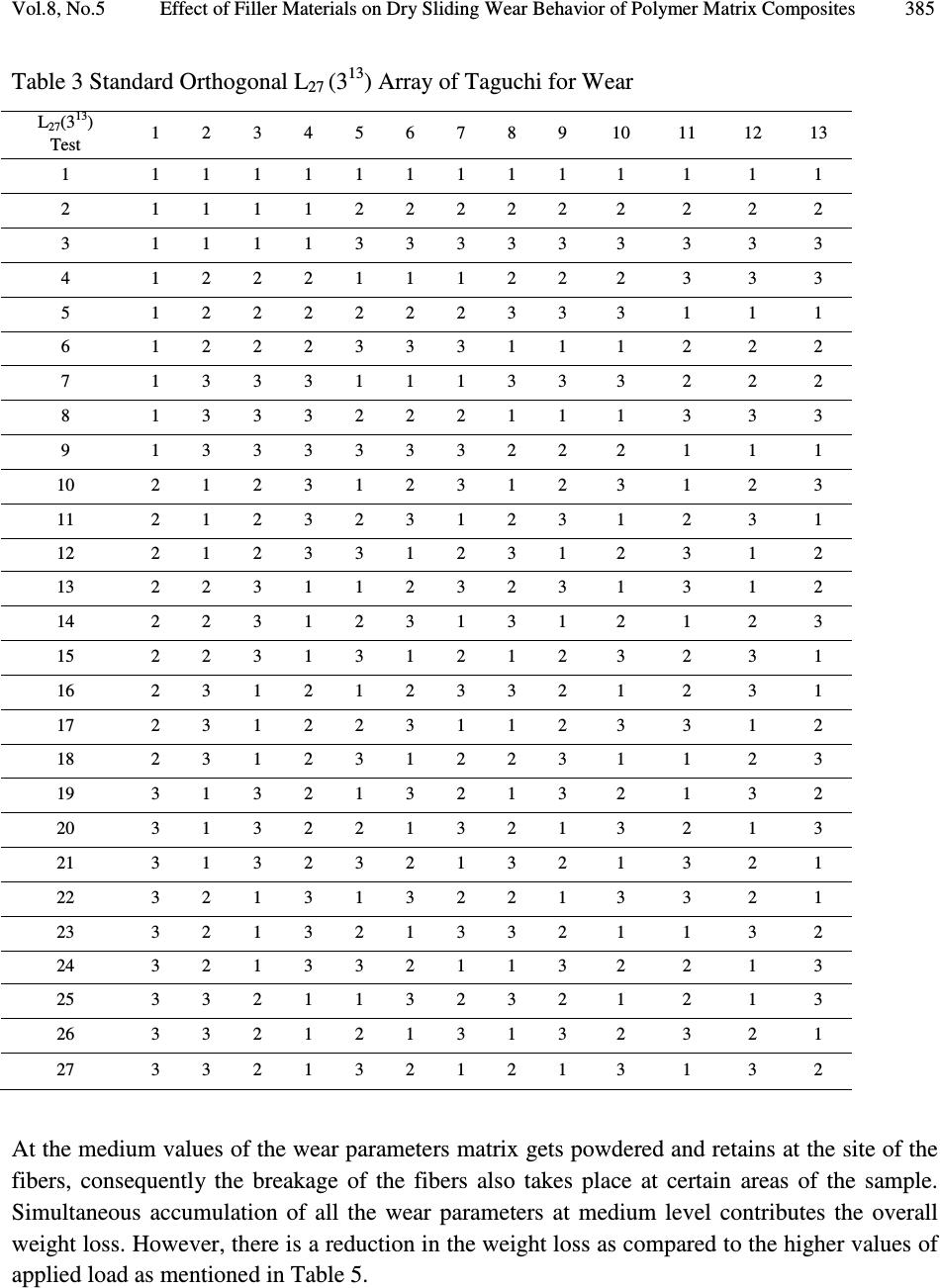 Vol.8, No.5 Effect of Filler Materials on Dry Sliding Wear Behavior of Polymer Matrix Composites 385 Table 3 Standard Orthogonal L 27 (3 13 ) Array of Taguchi for Wear At the medium values of the wear parameters matrix gets powdered and retains at the site of the fibers, consequently the breakage of the fibers also takes place at certain areas of the sample. Simultaneous accumulation of all the wear parameters at medium level contributes the overall weight loss. However, there is a reduction in the weight loss as compared to the higher values of applied load as mentioned in Table 5. L 27 (3 13 ) Test 1 2 3 4 5 6 7 8 9 10 11 12 13 1 1 1 1 1 1 1 1 1 1 1 1 1 1 2 1 1 1 1 2 2 2 2 2 2 2 2 2 3 1 1 1 1 3 3 3 3 3 3 3 3 3 4 1 2 2 2 1 1 1 2 2 2 3 3 3 5 1 2 2 2 2 2 2 3 3 3 1 1 1 6 1 2 2 2 3 3 3 1 1 1 2 2 2 7 1 3 3 3 1 1 1 3 3 3 2 2 2 8 1 3 3 3 2 2 2 1 1 1 3 3 3 9 1 3 3 3 3 3 3 2 2 2 1 1 1 10 2 1 2 3 1 2 3 1 2 3 1 2 3 11 2 1 2 3 2 3 1 2 3 1 2 3 1 12 2 1 2 3 3 1 2 3 1 2 3 1 2 13 2 2 3 1 1 2 3 2 3 1 3 1 2 14 2 2 3 1 2 3 1 3 1 2 1 2 3 15 2 2 3 1 3 1 2 1 2 3 2 3 1 16 2 3 1 2 1 2 3 3 2 1 2 3 1 17 2 3 1 2 2 3 1 1 2 3 3 1 2 18 2 3 1 2 3 1 2 2 3 1 1 2 3 19 3 1 3 2 1 3 2 1 3 2 1 3 2 20 3 1 3 2 2 1 3 2 1 3 2 1 3 21 3 1 3 2 3 2 1 3 2 1 3 2 1 22 3 2 1 3 1 3 2 2 1 3 3 2 1 23 3 2 1 3 2 1 3 3 2 1 1 3 2 24 3 2 1 3 3 2 1 1 3 2 2 1 3 25 3 3 2 1 1 3 2 3 2 1 2 1 3 26 3 3 2 1 2 1 3 1 3 2 3 2 1 27 3 3 2 1 3 2 1 2 1 3 1 3 2  386 S. Basavarajappa, K. V. Arun, J. Paulo Davim Vol.8, No.5 Table 4 Results of dry sliding wear tests as per Orthogonal Array of L 27 (3 13 ) L 27 (3 13 ) Test Speed in m/s Load in N Distance in m Wear in mg GE Wear in mg GE + SiCp Wear in mg GE + SiCp + Gr 1 3 20 1000 0.2 0.2 o0.2 2 3 20 2000 0.5 0.4 0.2 3 3 20 3000 1.0 0.7 0.8 4 3 40 1000 1.3 1.2 0.3 5 3 40 2000 3.2 1.7 0.5 6 3 40 3000 3.0 2.1 1.3 7 3 60 1000 2.5 1.4 0.6 8 3 60 2000 1.9 1.9 1.2 9 3 60 3000 3.0 2.1 0.3 10 4 20 1000 0.4 0.8 0.7 11 4 20 2000 0.8 0.8 0.2 12 4 20 3000 0.9 2.1 0.2 13 4 40 1000 1.0 1.1 1.9 14 4 40 2000 1.0 1.1 3.1 15 4 40 3000 1.2 0.8 1.1 16 4 60 1000 1.4 1.0 3.1 17 4 60 2000 2.5 2.3 6.6 18 4 60 3000 2.8 3.2 4.8 19 5 20 1000 0.2 0.2 0.2 20 5 20 2000 0.9 0.5 0.5 21 5 20 3000 1.8 1.0 0.6 22 5 40 1000 1.2 1.3 0.9 23 5 40 2000 1.8 2.3 0.8 24 5 40 3000 2.0 3.5 0.6 25 5 60 1000 1.5 1.9 0.6 26 5 60 2000 2.4 1.6 1.6 27 5 60 3000 2.3 3.0 2.4 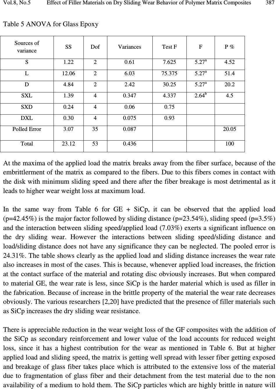 Vol.8, No.5 Effect of Filler Materials on Dry Sliding Wear Behavior of Polymer Matrix Composites 387 Table 5 ANOVA for Glass Epoxy At the maxima of the applied load the matrix breaks away from the fiber surface, because of the embrittlerment of the matrix as compared to the fibers. Due to this fibers comes in contact with the disk with minimum sliding speed and there after the fiber breakage is most detrimental as it leads to higher wear weight loss at maximum load. In the same way from Table 6 for GE + SiCp, it can be observed that the applied load (p=42.45%) is the major factor followed by sliding distance (p=23.54%), sliding speed (p=3.5%) and the interaction between sliding speed/applied load (7.03%) exerts a significant influence on the dry sliding wear. However the interactions between sliding speed/sliding distance and load/sliding distance does not have any significance they can be neglected. The pooled error is 24.31%. The table shows clearly as the applied load and sliding distance increases the wear rate also increases in most of the cases. This is because, whenever applied load increases, the friction at the contact surface of the material and rotating disc obviously increases. But when compared to material GE, the wear rate is less, since SiCp is the harder material which is used as filler in the fabrication. Because of increase in the brittle property of the material the wear rate decreases obviously. The various researchers [2,20] have predicted that the presence of filler materials such as SiCp increases the dry sliding wear resistance. There is appreciable reduction in the wear weight loss of the GF composites with the addition of the SiCp as secondary reinforcement and lower value of the load accounts for reduced weight loss, since it has a highest contribution for the wear as mentioned in Table 6. But at higher applied load and sliding speed, the matrix is getting well spread with lesser fiber getting exposed and breakage of glass fiber takes place which is attributed to the extensive loss of the material due to fragmentation of glass fiber and their detachment from the test material due to the non availability of a medium to hold them. The SiCp particles which are highly brittle in nature will Sources of variance SS Dof Variances Test F F P % S 1.22 2 0.61 7.625 5.27 a 4.52 L 12.06 2 6.03 75.375 5.27 a 51.4 D 4.84 2 2.42 30.25 5.27 a 20.2 SXL 1.39 4 0.347 4.337 2.64 b 4.5 SXD 0.24 4 0.06 0.75 DXL 0.30 4 0.075 0.93 Polled Error 3.07 35 0.087 20.05 Total 23.12 53 0.436 100  388 S. Basavarajappa, K. V. Arun, J. Paulo Davim Vol.8, No.5 be crushed into small particles when comes in contact with rotating disc. These small particles fill the voids which are formed during fabrication process. Table 6. ANOVA for GE+ SiCp ss = sum of variance, Dof=Degree of freedom a = 99% confidence, b = 95% confidence From the Table 7, it is observed that, as the applied load and sliding speed increases, the wear rate also increases in most of the cases. This is because, whenever applied load increases, the friction at the contact surface of the material and rotating disc obviously increases. Whereas the filler material Graphite acts as the self lubricating one, hence as the speed varies this affects the wear rate also in great manner when compared to GE and GE+SiCp material alone. But when compared to material GE and GE+SiCp the wear rate is less because of increase in the brittle and self lubricating properties of the material the wear rate decreases. It can also be observed that the applied load (p=28%) is the major factor followed by sliding speed (p=27%) and sliding distance (p=2.4%) and the interaction between sliding speed/applied load (12%) exerts a significant influence on the dry sliding wear. However the interactions between sliding speed/sliding distance and load/sliding distance does not have any significance they can be neglected. The pooled error is 29.31%. The various researchers have predicted that the presence of secondary reinforcement such as Graphite increases the dry sliding wear resistance. It is found that the wear initially controlled by the removal of graphite which acts as a self lubricating material due to less friction between the mat layer and rotating disc. But at higher applied load and sliding speed the matrix material is well spread and the graphite in the powder form is smeared the surface. Sources of variance SS Dof Variances Test F F P % S 0.9 2 0.45 4.78 4.12 b 3.5 L 8.9 2 4.45 47.34 5.27 a 42.45 D 5.02 2 2.51 26.70 5.27 a 23.54 SXL 1.82 4 0.445 4.73 2.64 b 7.03 SXD 0.30 4 0.075 0.797 DXL 0.28 4 0.07 0.744 Polled Error 3.3 35 0.094 24.31 Total 20.52 53 100  Vol.8, No.5 Effect of Filler Materials on Dry Sliding Wear Behavior of Polymer Matrix Composites 389 Table 7 ANOVA for GE+ SiCp + Gr Linear regression technique was used to study the dry wear weight loss of the composites. The generalized linear regression equation for the experiment can be written as, Y = a 0 + a 1 x 1 + a 2 x 2 + a 3 x 3 + a 4 x 1 x 2 + a 5 x 2 x 3 + a 6 x 3 x 1 + a 7 x 1 x 2 x 3 (1) The factorial design of experiments and the values of the response variables corresponding to each set of trials are represented in equation 1 for the specimen. Where Y is the wear weight loss. The variables x 1 , x 2 , x 2 are the L, D and S respectively [6-7]. The a 1 , a 2 and a 3 are the co- efficients of the independent variables x 1 , x 2 and x 3 respectively. The a 4 , a 5 , a 6 , and a 7 are the interaction co-efficients between x 1 x 2 , x 2 x 3 , x 1 x 3 and x 1 x 2 x 3 respectively, with on the selected levels of each variables. After calculating each of the coefficients of equation 1, the final linear regression equation for the wear rate of GE, GE+SiCp, GE+SiCp+Gr when tested against a pin on disc set up can be expressed as follows Regression Equation for GE is W = - 0.79 + 0.038 D + 0.0508 L + 0.000263 S - 0.0042 DxL + 0.000005 DxS + 0.000007 LxS - 0.000001 DxLxS (2) Regression Eq. for GE+ SiCp W = - 0.33 + 0.008 D + 0.0201 L + 0.000207 S + 0.0002 DxL + 0.000003 DxS+ 0.000000 LxS + 0.000001 DxLxS (3) Regression Eq. for GE+ SiCp+Gr W = - 0.27 + 0.009 D + 0.065 L + 0.000024 S - 0.0116 DxL - 0.000010 DxS - 0.000032 LxS + 0.000011 DxLxS (4) It is note from these equations that the coefficients of load (L), sliding distance (D) and sliding speed (S) are found to be positive. It indicates that load is the main factor on wear rate for three Sources of variance SS Dof Variances Test F F P % S 16.88. 2 8.44 24.11 27 L 17.48 2 8.74 24.97 28 D 2.14 2 1.075 3.07 2.4 SXL 8.55 4 2.14 6.11 12 SXD 1.43 4 0.36 1.028 0.1 DXL 2.19 4 0.55 1.571 1.4 Polled Error 12.11 35 0.346 29.1 Total 37.43 53 1.15 100  390 S. Basavarajappa, K. V. Arun, J. Paulo Davim Vol.8, No.5 of the test materials. It is followed by sliding distance while the sliding speed was less effective than the other parameters. The interaction coefficients between load/sliding speed, load/sliding distance, sliding speed/sliding distance are negative. This indicates that combined effects of these combinations are less effective on the wear rate. Also the interactions between the three variables are positive which will effect on the wear rate. 5. CONCLUSIONS Taguchi’s robust design method can be used to analyze the dry sliding wear problem of the polymer matrix composites as described in the paper. The following generalized conclusions can be drawn from the work. • The incorporation of the SiCp particles in the polymer matrix as a secondary reinforcement increases the wear resistance of the material. • Applied load is the wear factor that has the highest physical as well as statistical influence on the wear of both composites. • Design of experiments approach by taguchi method enabled us to analyze successfully the wear behavior of the composites with filler material, load, sliding distance and sliding speed as test variables. • Effect of variables i.e., load and sliding distance is more pronounced on the wear of the composite rather than sliding speed. • Factorial design of the experiment can be successfully employed to describe the wear behavior of the samples and to develop linear equations for predicting wear rate with in selected experimental conditions. REFERENCES [1] Sampathkumaran, K. P., Seetharamu, S., Vynatheya, S., Murali, S., Kumar, R.K., 2000, “SEM observations of the effects of velocity and load on the sliding wear characteristics of glass fabric–epoxy composites with different fillers.” Wear, Vol. 237, pp. 20–27. [2] Collyer, A.A., 1994, Rubber Toughened Engineering Materials, Chapman & Hall, London. [3] Pihtili, H., Tosun, N., 2002, “Investigation of the wear behaviour of a glass fibre-reinforced composite and plain polyester resin.” Composite Sci. Technol., Vol. 62, pp. 367–370. [4] El-Tayep, N.S., Gadelrap, R.M., 1996, “Friction and wear properties of E-glass fiber reinforced epoksi composites under different sliding contact conditions.” Wear, Vol. 192, pp. 112–117. [5] Chand, N., Naik, A., Neogi, S., 2000, “Three-body abrasive wear of short glass fibre polyester composite.” Wear, Vol. 242, pp. 38–46. [6] Piggot, M. R., 1980, Load-Bearing Fibre Composite, Pergamon Press, Oxford.  Vol.8, No.5 Effect of Filler Materials on Dry Sliding Wear Behavior of Polymer Matrix Composites 391 [7] Kukureka, S.N., Hooke, C. J., Rao, M., Liao, P., Chen, Y. K., 1999, “The effect of fibre- reinforcement on the friction and wear af polyamide 66 under dry rolling–sliding contact.” Tribol. Int., Vol. 32, pp. 107–116. [8] Zum Gahr, K.H., 1987, Microstructure and wear of materials, Tribology Series, Vol. 10, Elsevier, Amsterdam. [9] Friedrich, K., 1986, Friction and Wear of Polymer Composites, Composite Materials Series, Elsevier, Amsterdam, Vol. 1, pp. 233–287. [10] Xue, Q., Wang, Q., 1997 “Wear mechanisms of polyetheretherketone composites filled with various kinds of SiC.” Wear, Vol. 213, pp. 54-58. [11] Suresha, and Chandramohan, G., (Article in press), “Friction and Wear Characteristics of Carbon-epoxy and Glass-epoxy oven Roving Fiber Composites.” J.Reinforced Plastics and Composite. [12] Chandramohan, B. G., and Davim, J. P., “Application of Taguchi techniques to study the dry sliding wear behavior of metal matrix composites”. accepted 3 January 2006. [13] Taguchi, G., and Konishi, S., 1987 “Taguchi methods, orthogonal arrays and linear graphs, in tools for quality engineering.” American supplier institute, pp 35-38. [14] Taguchi, G., 1993, “Taguthi on robust technology development methods”, ASME press, New York, pp 1-40. [15] Ross, P. J., 1993, Taguchi technique for quality engineering, Mc Graw-Hill, New York, pp. 1-40. [16] Roy, K. R., 1990, A primer on Taguchi method, Van Nostrad reinhold, New York. [17] Basavarajappa, S., Chandrmohan, G., Mahadevan, A., Mukundan, Subramanian, R., Gopalakrishan, P., 2007, “Influence of sliding speed on the dry sliding wear behavior and the subsurface deformation of hybrid metal matrix composite.” Wear, Vol. 262, pp. 1007- 1012. [18] Suresha, B. , Chandramohan, G. , Prakash, J. N., Balusamy, V., Sankaranarayanasamy K., 2006, “The Role of Fillers on Friction and Slide Wear Characteristics in Glass-Epoxy Composite Systems.” Journal of Minerals & Materials Characterization & Engineering, Vol. 5, pp 87-101. |