Paper Menu >>
Journal Menu >>
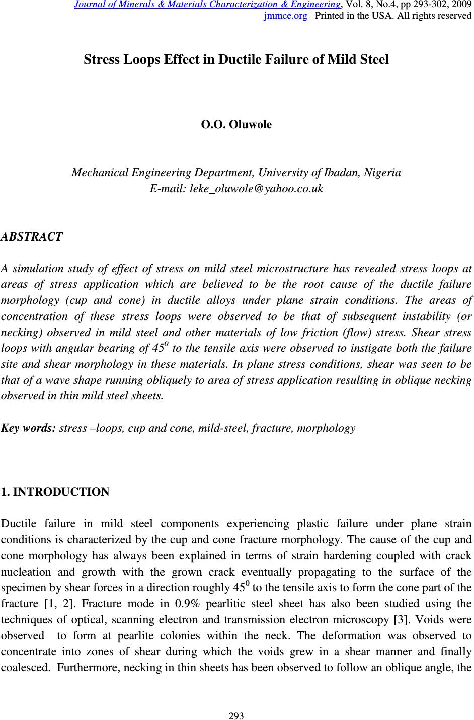 Journal of Minerals & Materials Characterization & Engineering, Vol. 8, No.4, pp 293-302, 2009 jmmce.org Printed in the USA. All rights reserved 293 Stress Loops Effect in Ductile Failure of Mild Steel O.O. Oluwole Mechanical Engineering Department, University of Ibadan, Nigeria E-mail: leke_oluwole@yahoo.co.uk ABSTRACT A simulation study of effect of stress on mild steel microstructure has revealed stress loops at areas of stress application which are believed to be the root cause of the ductile failure morphology (cup and cone) in ductile alloys under plane strain conditions. The areas of concentration of these stress loops were observed to be that of subsequent instability (or necking) observed in mild steel and other materials of low friction (flow) stress. Shear stress loops with angular bearing of 45 0 to the tensile axis were observed to instigate both the failure site and shear morphology in these materials. In plane stress conditions, shear was seen to be that of a wave shape running obliquely to area of stress application resulting in oblique necking observed in thin mild steel sheets. Key words: stress –loops, cup and cone, mild-steel, fracture, morphology 1. INTRODUCTION Ductile failure in mild steel components experiencing plastic failure under plane strain conditions is characterized by the cup and cone fracture morphology. The cause of the cup and cone morphology has always been explained in terms of strain hardening coupled with crack nucleation and growth with the grown crack eventually propagating to the surface of the specimen by shear forces in a direction roughly 45 0 to the tensile axis to form the cone part of the fracture [1, 2]. Fracture mode in 0.9% pearlitic steel sheet has also been studied using the techniques of optical, scanning electron and transmission electron microscopy [3]. Voids were observed to form at pearlite colonies within the neck. The deformation was observed to concentrate into zones of shear during which the voids grew in a shear manner and finally coalesced. Furthermore, necking in thin sheets has been observed to follow an oblique angle, the 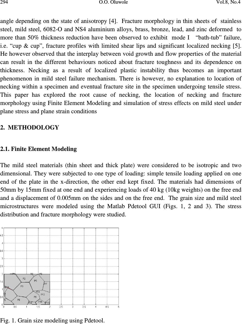 294 O.O. Oluwole Vol.8, No.4 angle depending on the state of anisotropy [4]. Fracture morphology in thin sheets of stainless steel, mild steel, 6082-O and NS4 aluminium alloys, brass, bronze, lead, and zinc deformed to more than 50% thickness reduction have been observed to exhibit mode I “bath-tub” failure, i.e. “cup & cup”, fracture profiles with limited shear lips and significant localized necking [5]. He however observed that the interplay between void growth and flow properties of the material can result in the different behaviours noticed about fracture toughness and its dependence on thickness. Necking as a result of localized plastic instability thus becomes an important phenomenon in mild steel failure mechanism. There is however, no explanation to location of necking within a specimen and eventual fracture site in the specimen undergoing tensile stress. This paper has explored the root cause of necking, the location of necking and fracture morphology using Finite Element Modeling and simulation of stress effects on mild steel under plane stress and plane strain conditions 2. METHODOLOGY 2.1. Finite Element Modeling The mild steel materials (thin sheet and thick plate) were considered to be isotropic and two dimensional. They were subjected to one type of loading: simple tensile loading applied on one end of the plate in the x-direction, the other end kept fixed. The materials had dimensions of 50mm by 15mm fixed at one end and experiencing loads of 40 kg (10kg weights) on the free end and a displacement of 0.005mm on the sides and on the free end. The grain size and mild steel microstructures were modeled using the Matlab Pdetool GUI (Figs. 1, 2 and 3). The stress distribution and fracture morphology were studied. Fig. 1. Grain size modeling using Pdetool. 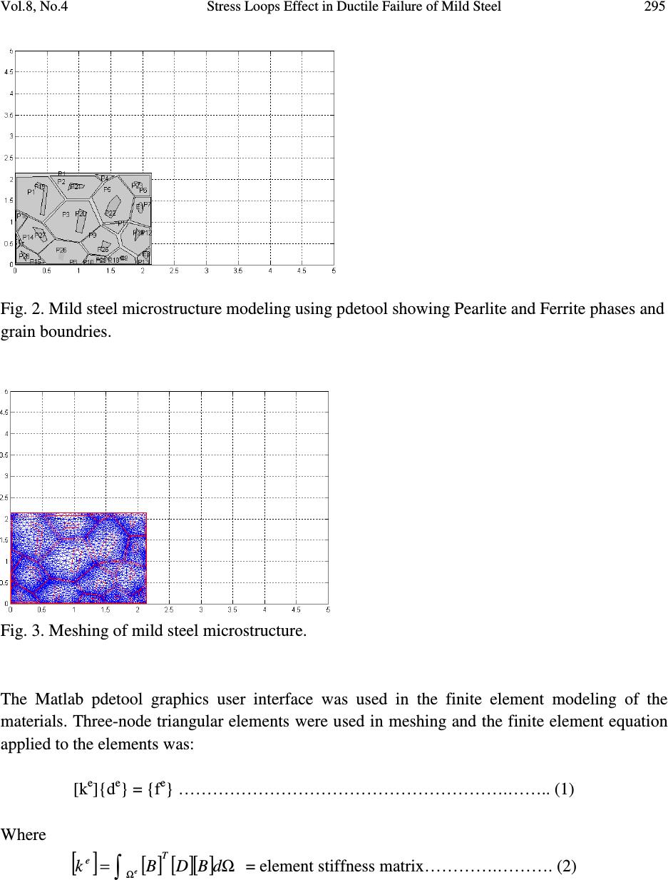 Vol.8, No.4 Stress Loops Effect in Ductile Failure of Mild Steel 295 Fig. 2. Mild steel microstructure modeling using pdetool showing Pearlite and Ferrite phases and grain boundries. Fig. 3. Meshing of mild steel microstructure. The Matlab pdetool graphics user interface was used in the finite element modeling of the materials. Three-node triangular elements were used in meshing and the finite element equation applied to the elements was: [k e ]{d e } = {f e } ………………………………………………….…….. (1) Where [ ] [ ][][ ] Ω= ∫ Ω dBDBk T e e = element stiffness matrix………….………. (2)  296 O.O. Oluwole Vol.8, No.4 [B e ] = ∂ ∂ ∂ ∂ ∂ ∂ ∂ ∂ ∂ ∂ ∂ ∂ ∂ ∂ ∂ ∂ ∂ ∂∂ ∂ ∂ ∂ ∂ ∂ x N y N x N y N x N y N y N y N y N x N x N x N 332211 3 21 3 21 000 000 ………….………….. (3) [D] = − − − − −+ − )1(2 21 00 01 1 0 1 1 )21)(1( )1( ν ν ν νν ν νν ν E for plane strain condition ……….. (4) − − = 2 1 00 01 01 )1( ][ 2 ν ν ν ν E D for plane stress condition……………………………(5) N 1 , N 2 and N 3 are shape functions for three-node triangular elements. x and y are the directions in which the forces are acting E = Youngs modulus of elasticity ν = Poisson ratio {f e } = element force vector {d e }= element displacement vector 2.2. Assembly of Element Equations into Global Equation and Solving for Displacements The elemental equations were assembled and solved using the global equation: [k]\{f} = {d} …………………………..…………………………..……(6) Where {d} = Nodal displacement vector = {u 1 v 1 u 2 v 2 u 3 v 3 } T ………………... (7)  Vol.8, No.4 Stress Loops Effect in Ductile Failure of Mild Steel 297 2.3. Solving for Strains, Stress and Shear Stress and Strains Solving for strains, the kinematic equation relating strains to displacements stated below in equation (8) was used: ∂ ∂ + ∂ ∂ ∂ ∂ ∂ ∂ = x v y u y v x u xy y x γ ε ε ………………………………………………………(8) Solving for stresses, the constitutive equation between stress and strain as stated in equation (9) below was used; { } [ ] { } εσ D= ………………………………………….………………………(9) For shear stresses, equations of equilibrium of forces acting on two-dimensional continuum were used. These are: 0=+ ∂ ∂ + ∂ ∂ x xy x f yx τ σ …………………………..………………………..(10) and 0=+ ∂ ∂ + ∂ ∂ y yxy f yx σ τ ………………………..…………………………….(11) Where xyyx τσσ ,, are stresses acting in the x, y directions and Shear stress respectively. 3. RESULTS AND DISCUSSION 3.1. Elongation at Stress The results of elongation on stressing are presented in Figs. 4 and 5 for plane strain and plane stress conditions respectively. Extension was observed to be more under plane stress conditions for the same length of material. This was expected as the sheet under extension would elongate more than the bar.  298 O.O. Oluwole Vol.8, No.4 3.2. x-stress Distribution The results of the stress component in the x-direction are presented in Figs. 6 and 7 for plane strain and stress conditions respectively. Large tensile stress loop was observed in the mild steel under plane strain while smaller tensile stress loop was observed in the steel under plane stress conditions. Compressive stresses were observed acting closer to the area of applied stress. Under plane stress conditions it was observed that tensile stresses were larger on both sides of the sheet with compressive stresses dominant in the sheet. PLANE STRAIN Fig.4:x-displacement under plane strain PLANE STRESS Fig.5:x-displacement under plane stress Fig.6a:x-stress in plane strain conditions Fig.7a:x-stress in plane stress conditions  Vol.8, No.4 Stress Loops Effect in Ductile Failure of Mild Steel 299 Fig.6b:x-stress in plane strain conditions Fig.7b:x-stress in plane stress conditions 3.3. y-stress Distribution The results of the stress component in the y-direction are presented in Figs. 8 and 9 for plane strain and plane stress conditions respectively. Compressive stresses are dominant in the mild steel with areas of tensile stress loop observed in the materials. This observation coupled with the x-stress distribution already showed the interplay of stresses leading up to shearing stresses and fracture morphology. The longer tensile y-stress loop almost stretching across the mild steel sheet was observed under plane stress which already pointed to the vertical tearing failure of the sheet. 3.4. Shearing Stresses and Strains The interplay between the x and y components of stress culminated in the shearing stresses shown in Figs. 10 and 11 for plane strain and plane stress conditions respectively. Shearing stresses could be seen running obliquely in a wave form (Fig. 11a) down the sheet under plane stress conditions culminating in the oblique necking [4] and subsequent shear morphology observed in failed sheets subjected to tensile stress failures. In the mild steel under plane strain it was observed that the shearing stress loops on both sides of the materials stop within the material (Fig. 10a). The angular concentration of the shearing stresses help in creating the instability or necking observed in plane strain conditions and the compressive shearing stresses help in creating the much noticed cup and cone fracture morphology (Figs. 10b and 14). The results showed that shear stresses acting on the mild steel sample concentrated nearer the area of stress application than at the fixed end and the intensity of the shear stress loops effected the localization of the necking phenomenon and eventual cup and  300 O.O. Oluwole Vol.8, No.4 cone fracture morphology. The angular direction of the stress loops indicated what the shear morphology would be. The shearing strains were observed to follow the same trend as the shearing stresses obtained for both plane stress and plane strain conditions (Figs. 12 and 13). 4. CONCLUSION A simulation study of effect of stress on mild steel microstructure has revealed stress loops at areas of stress application which are believed to be the root cause of the ductile failure morphology (cup and cone) in ductile alloys under plane strain conditions. The area of concentration of these stress loops were observed to be that of subsequent instability (or necking) observed in mild steel and other materials of low friction (flow) stress. Shear stress loops were observed to instigate the shear morphology in these materials. In plane stress conditions shear stress was seen to be that of a wave shape running parallel to area of stress application resulting in the oblique necking observed in mild steel sheets. Fig.8a:y-stress in plane strain conditions Fig.9a:y-stress in plane stress conditions Fig.8b:y-stress in plane strain conditions Fig.9b:y-stress in plane stress conditions 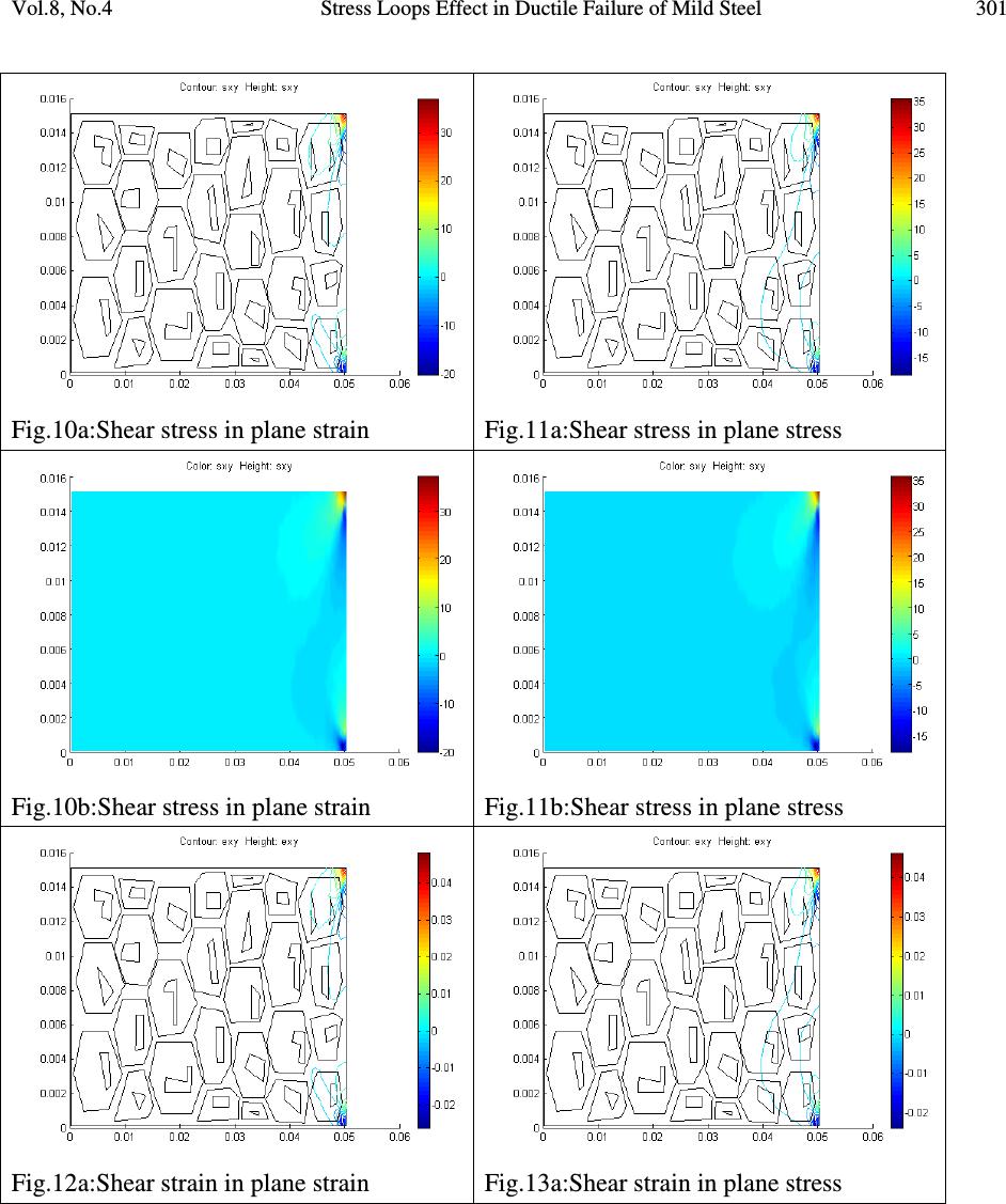 Vol.8, No.4 Stress Loops Effect in Ductile Failure of Mild Steel 301 Fig.10a:Shear stress in plane strain Fig.11a:Shear stress in plane stress Fig.10b:Shear stress in plane strain Fig.11b:Shear stress in plane stress Fig.12a:Shear strain in plane strain Fig.13a:Shear strain in plane stress 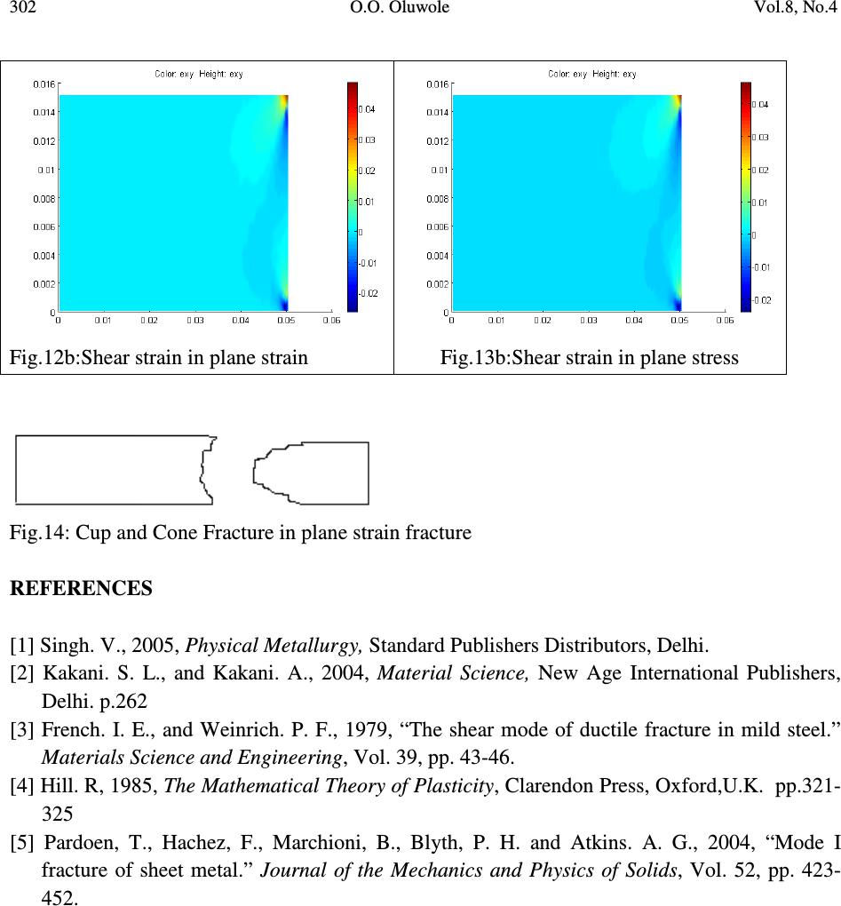 302 O.O. Oluwole Vol.8, No.4 Fig.12b:Shear strain in plane strain Fig.13b:Shear strain in plane stress Fig.14: Cup and Cone Fracture in plane strain fracture REFERENCES [1] Singh. V., 2005, Physical Metallurgy, Standard Publishers Distributors, Delhi. [2] Kakani. S. L., and Kakani. A., 2004, Material Science, New Age International Publishers, Delhi. p.262 [3] French. I. E., and Weinrich. P. F., 1979, “The shear mode of ductile fracture in mild steel.” Materials Science and Engineering , Vol. 39, pp. 43-46. [4] Hill. R, 1985, The Mathematical Theory of Plasticity , Clarendon Press, Oxford,U.K. pp.321- 325 [5] Pardoen, T., Hachez, F., Marchioni, B., Blyth, P. H. and Atkins. A. G., 2004, “Mode I fracture of sheet metal.” Journal of the Mechanics and Physics of Solids , Vol. 52, pp. 423- 452. |