Paper Menu >>
Journal Menu >>
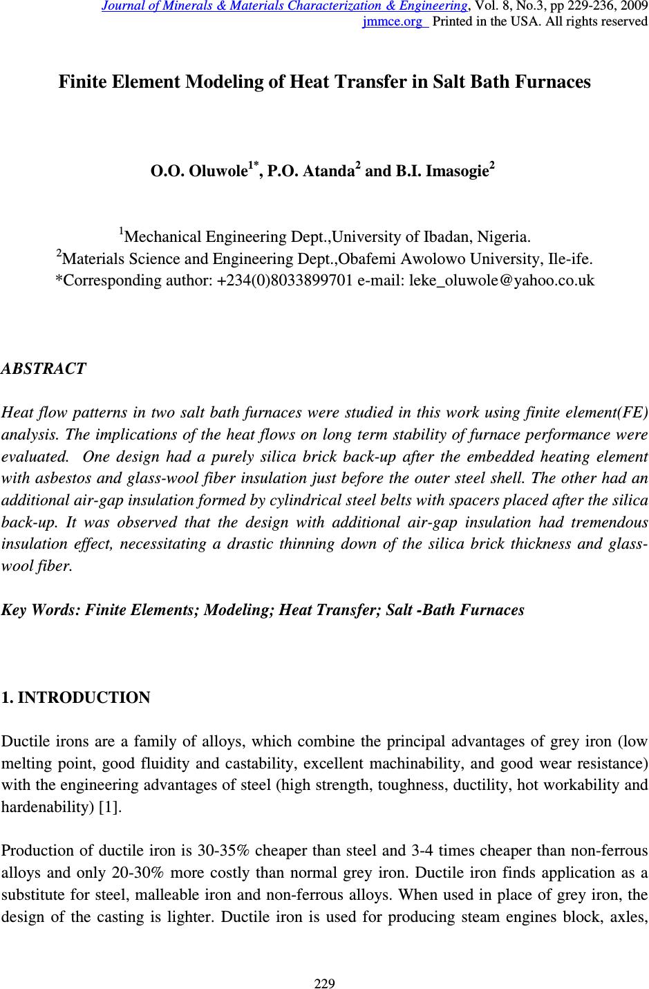 Journal of Minerals & Materials Characterization & Engineering, Vol. 8, No.3, pp 229-236, 2009 jmmce.org Printed in the USA. All rights reserved 229 Finite Element Modeling of Heat Transfer in Salt Bath Furnaces O.O. Oluwole 1* , P.O. Atanda 2 and B.I. Imasogie 2 1 Mechanical Engineering Dept.,University of Ibadan, Nigeria. 2 Materials Science and Engineering Dept.,Obafemi Awolowo University, Ile-ife. *Corresponding author: +234(0)8033899701 e-mail: leke_oluwole@yahoo.co.uk ABSTRACT Heat flow patterns in two salt bath furnaces were studied in this work using finite element(FE) analysis. The implications of the heat flows on long term stability of furnace performance were evaluated. One design had a purely silica brick back-up after the embedded heating element with asbestos and glass-wool fiber insulation just before the outer steel shell. The other had an additional air-gap insulation formed by cylindrical steel belts with spacers placed after the silica back-up. It was observed that the design with additional air-gap insulation had tremendous insulation effect, necessitating a drastic thinning down of the silica brick thickness and glass- wool fiber. Key Words: Finite Elements; Modeling; Heat Transfer; Salt -Bath Furnaces 1. INTRODUCTION Ductile irons are a family of alloys, which combine the principal advantages of grey iron (low melting point, good fluidity and castability, excellent machinability, and good wear resistance) with the engineering advantages of steel (high strength, toughness, ductility, hot workability and hardenability) [1]. Production of ductile iron is 30-35% cheaper than steel and 3-4 times cheaper than non-ferrous alloys and only 20-30% more costly than normal grey iron. Ductile iron finds application as a substitute for steel, malleable iron and non-ferrous alloys. When used in place of grey iron, the design of the casting is lighter. Ductile iron is used for producing steam engines block, axles, 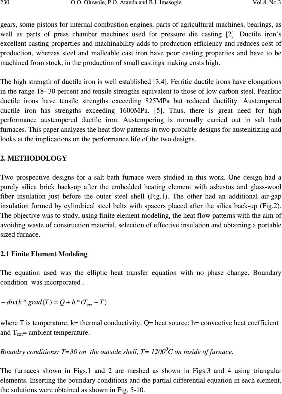 230 O.O. Oluwole, P.O. Atanda and B.I. Imasogie Vol.8, No.3 gears, some pistons for internal combustion engines, parts of agricultural machines, bearings, as well as parts of press chamber machines used for pressure die casting [2]. Ductile iron’s excellent casting properties and machinability adds to production efficiency and reduces cost of production, whereas steel and malleable cast iron have poor casting properties and have to be machined from stock, in the production of small castings making costs high. The high strength of ductile iron is well established [3,4]. Ferritic ductile irons have elongations in the range 18- 30 percent and tensile strengths equivalent to those of low carbon steel. Pearlitic ductile irons have tensile strengths exceeding 825MPa but reduced ductility. Austempered ductile iron has strengths exceeding 1600MPa. [5]. Thus, there is great need for high performance austempered ductile iron. Austempering is normally carried out in salt bath furnaces. This paper analyzes the heat flow patterns in two probable designs for austenitizing and looks at the implications on the performance life of the two designs. 2. METHODOLOGY Two prospective designs for a salt bath furnace were studied in this work. One design had a purely silica brick back-up after the embedded heating element with asbestos and glass-wool fiber insulation just before the outer steel shell (Fig.1). The other had an additional air-gap insulation formed by cylindrical steel belts with spacers placed after the silica back-up (Fig.2). The objective was to study, using finite element modeling, the heat flow patterns with the aim of avoiding waste of construction material, selection of effective insulation and obtaining a portable sized furnace. 2.1 Finite Element Modeling The equation used was the elliptic heat transfer equation with no phase change. Boundary condition was incorporated . )(*)(*( TThQTgradkdiv ext −+=− where T is temperature; k= thermal conductivity; Q= heat source; h= convective heat coefficient and T ext = ambient temperature. Boundry conditions: T=30 on the outside shell, T= 1200 0 C on inside of furnace. The furnaces shown in Figs.1 and 2 are meshed as shown in Figs.3 and 4 using triangular elements. Inserting the boundary conditions and the partial differential equation in each element, the solutions were obtained as shown in Fig. 5-10. 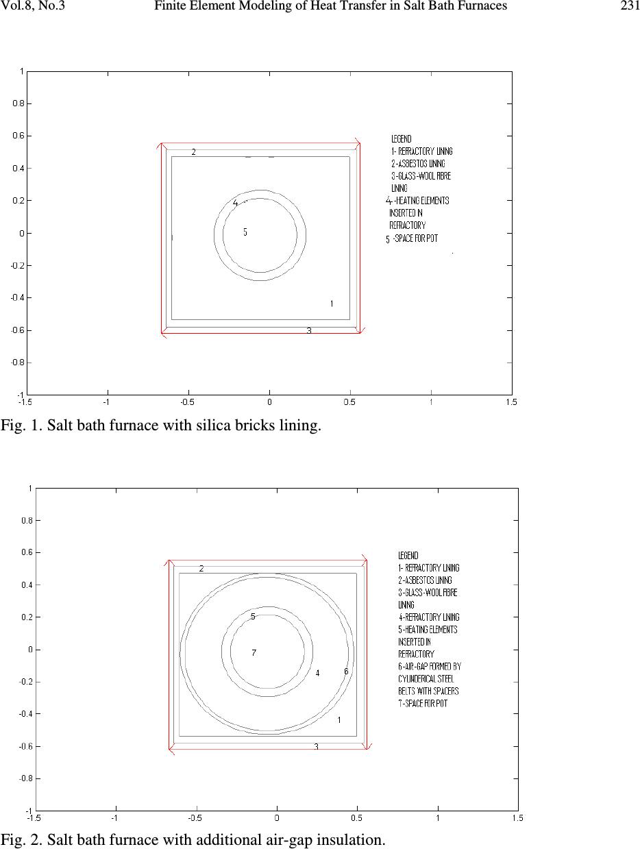 Vol.8, No.3 Finite Element Modeling of Heat Transfer in Salt Bath Furnaces 231 Fig. 1. Salt bath furnace with silica bricks lining. Fig. 2. Salt bath furnace with additional air-gap insulation.  232 O.O. Oluwole, P.O. Atanda and B.I. Imasogie Vol.8, No.3 Fig. 3. Meshing of the Salt Bath Furnace with air-gap within refractory lining for FE analysis. Fig. 4. Meshing of Salt Bath Furnace without air-gap in refractory lining for FE analysis. 3. RESULTS AND DISCUSSION 3.1 Results The results of the modeling are found in Figs. 5-10. Figs. 5a and b show the temperature profiles in the salt bath furnace with air-gap insulation incorporated in the refractory lining. The figures show the temperature in the austenitizing pot at 1200 0 C. The temperature fell to about 600 0 C from 800 0 C in the refractory lining and from 600 0 C to 350 0 C in the air-gap. The temperature in the asbestos lining fell from 350 to 200 0 C and the temperature in the glass wool from 200 0 C to less than 100 0 C. Figs.6a and b present the temperature profiles in the salt bath furnace that has no air-gap insulation in the refractory lining. The temperature profiles show temperatures in the bath at 1200 0 C, and the temperature in the refractory lining falling from 800 0 C to 600 0 C. The temperature in the asbestos lining fell from 600 0 C to 500 0 C while that in the glass wool fell from 500 0 C to less than 100 0 C. Figs. 7and b show the heat flux occurring in the salt bath furnace that has air-gap insulator incorporated in the refractory lining. The heat flux inside the furnace is about 100 W/m 2 . The heat flux was observed to be highest in the refractory lining about 600W/m 2 falling in the air-gap and further still in the asbestos and glass wool. The heat flux in the refractory outlining the air- gap as well was observed to be 100 0 C as in the asbestos and glass-wool. Figs. 8a and b show heat flux in the salt bath furnace with no air-gap insulator. The heat flux in the refractory lining and asbestos was observed to be 300 0 C. In the glass wool it was observed to be 200 0 C. Figs. 9a and b show the temperature gradients in the furnace incorporated with air-gap insulator. They show a very high temperature gradient in the air-gap insulation. Figs.10a and b shows temperature gradients in the furnace without air-gap insulation to be highest in the glass wool insulation. .  Vol.8, No.3 Finite Element Modeling of Heat Transfer in Salt Bath Furnaces 233 Fig.5a: The Salt Bath furnace with air-gap showing the temperatures profiles from the pot to the shell.We can see the temp at the shell falling to 30 0 C and the inside temp.1200 0 C Fig.6a: The Salt Bath furnace with air-gap showing the temperatures profiles from the pot to the shell Fig.5b: A 3-Dimensional presentation of the Temperature profiles in the furnace . Fig.7a: The Salt Bath Furnace with refractory air-gap showing Heat flux from the heating coils through the refractory insulation to the shell. We could see that the majority of the heat is retained in the refractory bricks. The heat flux inside the furnace is constant because it is not expected to fluctuate after reaching the desired temperature. Fig.6b: A 3-D presentation of the salt bath furnace with air-gap showing the temperatures profiles from the pot to the shell. Fig.8a: Salt Bath Furnace with no air-gap insulation showing Heat flux from the heating coils through the refractory insulation to the shell. 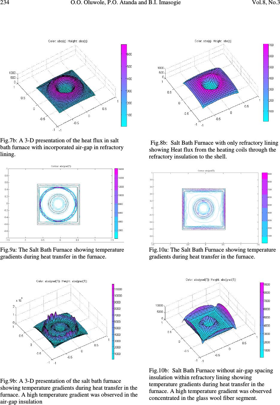 234 O.O. Oluwole, P.O. Atanda and B.I. Imasogie Vol.8, No.3 Fig.7b: A 3-D presentation of the heat flux in salt bath furnace with incorporated air-gap in refractory lining. Fig.8b: Salt Bath Furnace with only refractory lining showing Heat flux from the heating coils through the refractory insulation to the shell. Fig.9a: The Salt Bath Furnace showing temperature gradients during heat transfer in the furnace. Fig.10a: The Salt Bath Furnace showing temperature gradients during heat transfer in the furnace. Fig.9b: A 3-D presentation of the salt bath furnace showing temperature gradients during heat transfer in the furnace. A high temperature gradient was observed in the air-gap insulation Fig.10b: Salt Bath Furnace without air-gap spacing insulation within refractory lining showing temperature gradients during heat transfer in the furnace. A high temperature gradient was observed concentrated in the glass wool fiber segment. 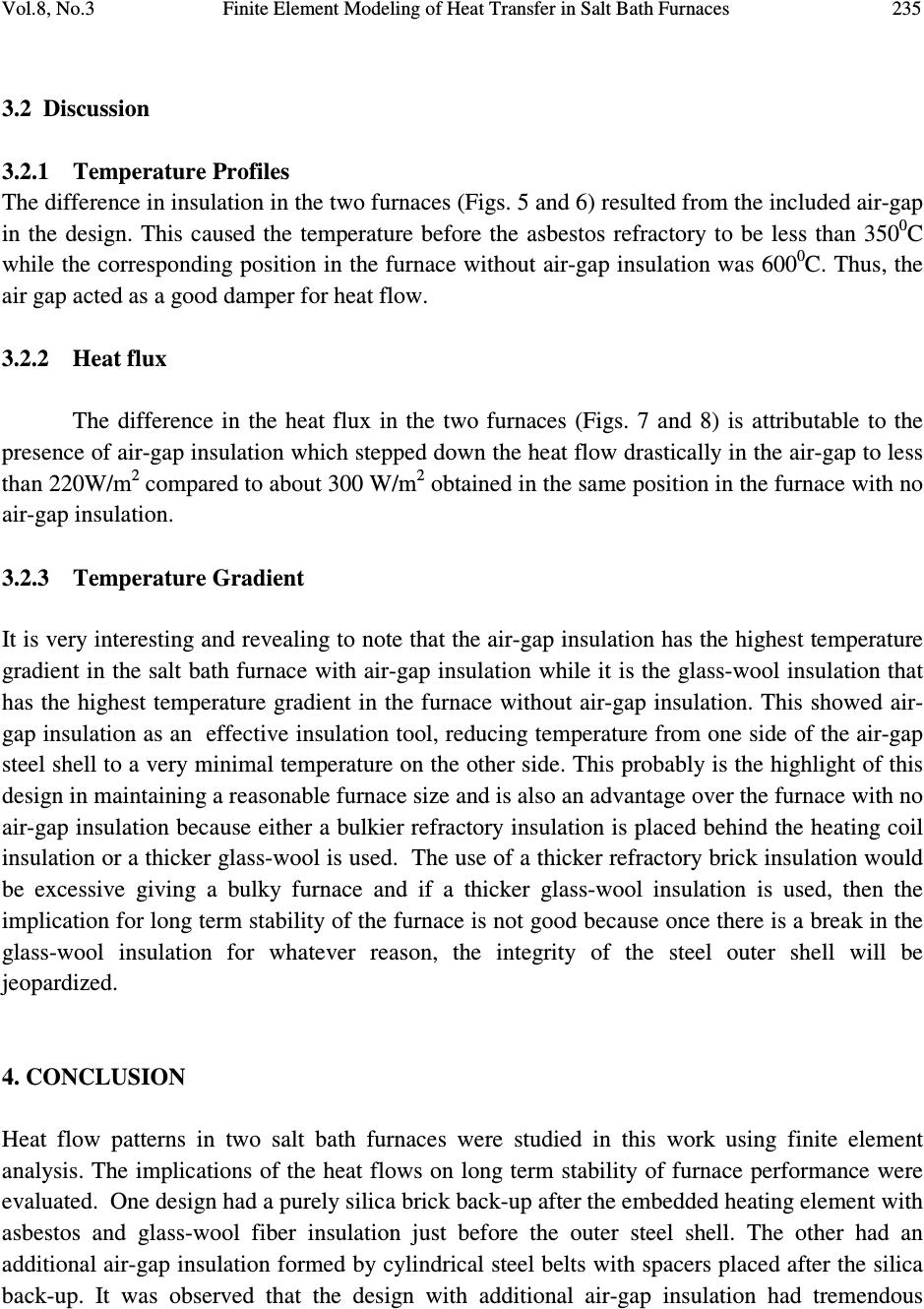 Vol.8, No.3 Finite Element Modeling of Heat Transfer in Salt Bath Furnaces 235 3.2 Discussion 3.2.1 Temperature Profiles The difference in insulation in the two furnaces (Figs. 5 and 6) resulted from the included air-gap in the design. This caused the temperature before the asbestos refractory to be less than 350 0 C while the corresponding position in the furnace without air-gap insulation was 600 0 C. Thus, the air gap acted as a good damper for heat flow. 3.2.2 Heat flux The difference in the heat flux in the two furnaces (Figs. 7 and 8) is attributable to the presence of air-gap insulation which stepped down the heat flow drastically in the air-gap to less than 220W/m 2 compared to about 300 W/m 2 obtained in the same position in the furnace with no air-gap insulation. 3.2.3 Temperature Gradient It is very interesting and revealing to note that the air-gap insulation has the highest temperature gradient in the salt bath furnace with air-gap insulation while it is the glass-wool insulation that has the highest temperature gradient in the furnace without air-gap insulation. This showed air- gap insulation as an effective insulation tool, reducing temperature from one side of the air-gap steel shell to a very minimal temperature on the other side. This probably is the highlight of this design in maintaining a reasonable furnace size and is also an advantage over the furnace with no air-gap insulation because either a bulkier refractory insulation is placed behind the heating coil insulation or a thicker glass-wool is used. The use of a thicker refractory brick insulation would be excessive giving a bulky furnace and if a thicker glass-wool insulation is used, then the implication for long term stability of the furnace is not good because once there is a break in the glass-wool insulation for whatever reason, the integrity of the steel outer shell will be jeopardized. 4. CONCLUSION Heat flow patterns in two salt bath furnaces were studied in this work using finite element analysis. The implications of the heat flows on long term stability of furnace performance were evaluated. One design had a purely silica brick back-up after the embedded heating element with asbestos and glass-wool fiber insulation just before the outer steel shell. The other had an additional air-gap insulation formed by cylindrical steel belts with spacers placed after the silica back-up. It was observed that the design with additional air-gap insulation had tremendous  236 O.O. Oluwole, P.O. Atanda and B.I. Imasogie Vol.8, No.3 insulation effect, necessitating a drastic thinning down of the silica brick thickness and glass- wool fiber. REFERENCES [1] Heine, R.W., Coper, C.R. and Rosenthal P.C (1976): “Principles of Engineering alloys”, 2nd ed. Tata Mcgraw – Hill, New Delhi [2] John, V. B. (1992): “Introduction to Engineering Materials” 3rd ed. Macmillian press Ltd, London. [3] Walton, C.F and Opar, T.J. (1981): “Iron casting handbook covering data on Grey, Malleable and ductile iron, Iron casting Society Inc. New York. [4] Smith, W.F., (1993): “Structure and properties of Engineering alloys”, 2nd ed. McGraw- Hill, New York [5] Ductile Iron Society (2006) “Ductile Iron Data for Design Engineers”, http://www.ductile.org/didata/Section3/3part2.htm#Fracture%20Behaviour |