Paper Menu >>
Journal Menu >>
 Journal of Minerals & Materials Characterization & Engineering, Vol. 8, No.2, pp 133-148, 2009 jmmce.org Printed in the USA. All rights reserved Lengthening, Cracking and Weldability Problems of Fe–Ni–Cr Alloy Tube Ali Babakr* and Fakhruddin Habiby SABIC Technology Center P.O. Box 11669 Jubail, Saudi Arabia 31961 *Corresponding Author: alibabakr@yahoo.com ABSTRACT Ethylene pyrolysis furnace tubes which are made of high Cr-Ni alloys often become difficult to weld after few years in service due to carburization and creep damage. The presence of carburization, often attempted to detect by magnetic permeability, can escape detection due to high Cr-Ni content of the alloy. Based on optical microstructural analysis and supported by scanning electron microscopy, this paper establishes that car b ur i z e d material becomes difficult to weld due to carburized internal layers of the tube and cause hot shortness. To provide a practical way out for ethylene furnace operators, a solution annealing heat- treatment is recommended to have a successful weld. Keywords: ethylene, furnace, olefins, pyrolysis, steam cracking, Microstructure 1. INTRODUCTION In a typical ethylene furnace the pyrolysis reaction is endothermic. For this reason, the material must be suitable to accommodate the high process temperature. Continual improvement of tubular materials and furnace design has made it possible to accommodate 750 – 850oC and up to 900oC or even higher [1]. The tubular coils within an industrial pyrolysis furnace are usually made of the base Cr/Ni alloys and grow in popularity [2]. The coils are hung vertically in a firebox and vary in number according to design. These alloys are selected for their better cocking [3,4]/erosion resistance, high creep strength [5,6], carburization resistance [7], ductility, and thermal shock resistance [8]. Many challenges can be encountered when trying to establish a proper welding procedure utilizing a suitable filler metal taken into consideration of its corrosion, mechanical and alloying elements. Several problems had been experienced in furnaces at a petrochemical plant comprising of permanent longitudinal tube growth and weldability problems [9,10,11]. 133 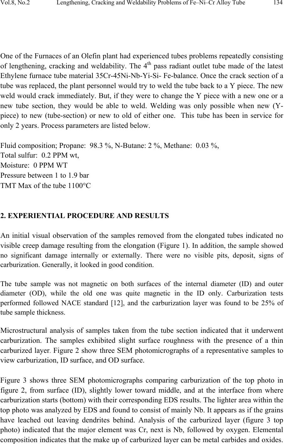 Vol.8, No.2 Lengthening, Cracking and Weldability Problems of Fe–Ni–Cr Alloy Tube 134 One of the Furnaces of an Olefin plant had experienced tubes problems repeatedly consisting of lengthening, cracking and weldability. The 4th pass radiant outlet tube made of the latest Ethylene furnace tube material 35Cr-45Ni-Nb-Yi-Si- Fe-balance. Once the crack section of a tube was replaced, the plant personnel would try to weld the tube back to a Y piece. The new weld would crack immediately. But, if they were to change the Y piece with a new one or a new tube section, they would be able to weld. Welding was only possible when new (Y- piece) to new (tube-section) or new to old of either one. This tube has been in service for only 2 years. Process parameters are listed below. Fluid composition; Propane: 98.3 %, N-Butane: 2 %, Methane: 0.03 %, Total sulfur: 0.2 PPM wt, Moisture: 0 PPM WT Pressure between 1 to 1.9 bar TMT Max of the tube 1100°C 2. EXPERIENTIAL PROCEDURE AND RESULTS An initial visual observation of the samples removed from the elongated tubes indicated no visible creep damage resulting from the elongation (Figure 1). In addition, the sample showed no significant damage internally or externally. There were no visible pits, deposit, signs of carburization. Generally, it looked in good condition. The tube sample was not magnetic on both surfaces of the internal diameter (ID) and outer diameter (OD), while the old one was quite magnetic in the ID only. Carburization tests performed followed NACE standard [12], and the carburization layer was found to be 25% of tube sample thickness. Microstructural analysis of samples taken from the tube section indicated that it underwent carburization. The samples exhibited slight surface roughness with the presence of a thin carburized layer. Figure 2 show three SEM photomicrographs of a representative samples to view carburization, I D s u rface, and OD surface. Figure 3 shows three SEM photomicrographs comparing carburization of the top photo in figure 2, from surface (ID), slightly lower toward middle, and at the interface from where carburization starts (bottom) with their corresponding EDS results. The lighter area within the top photo was analyzed by EDS and found to consist of mainly Nb. It appears as if the grains have leached out leaving dendrites behind. Analysis of the carburized layer (figure 3 top photo) indicated that the major element was Cr, next is Nb, followed by oxygen. Elemental composition indicates that the make up of carburized layer can be metal carbides and oxides. 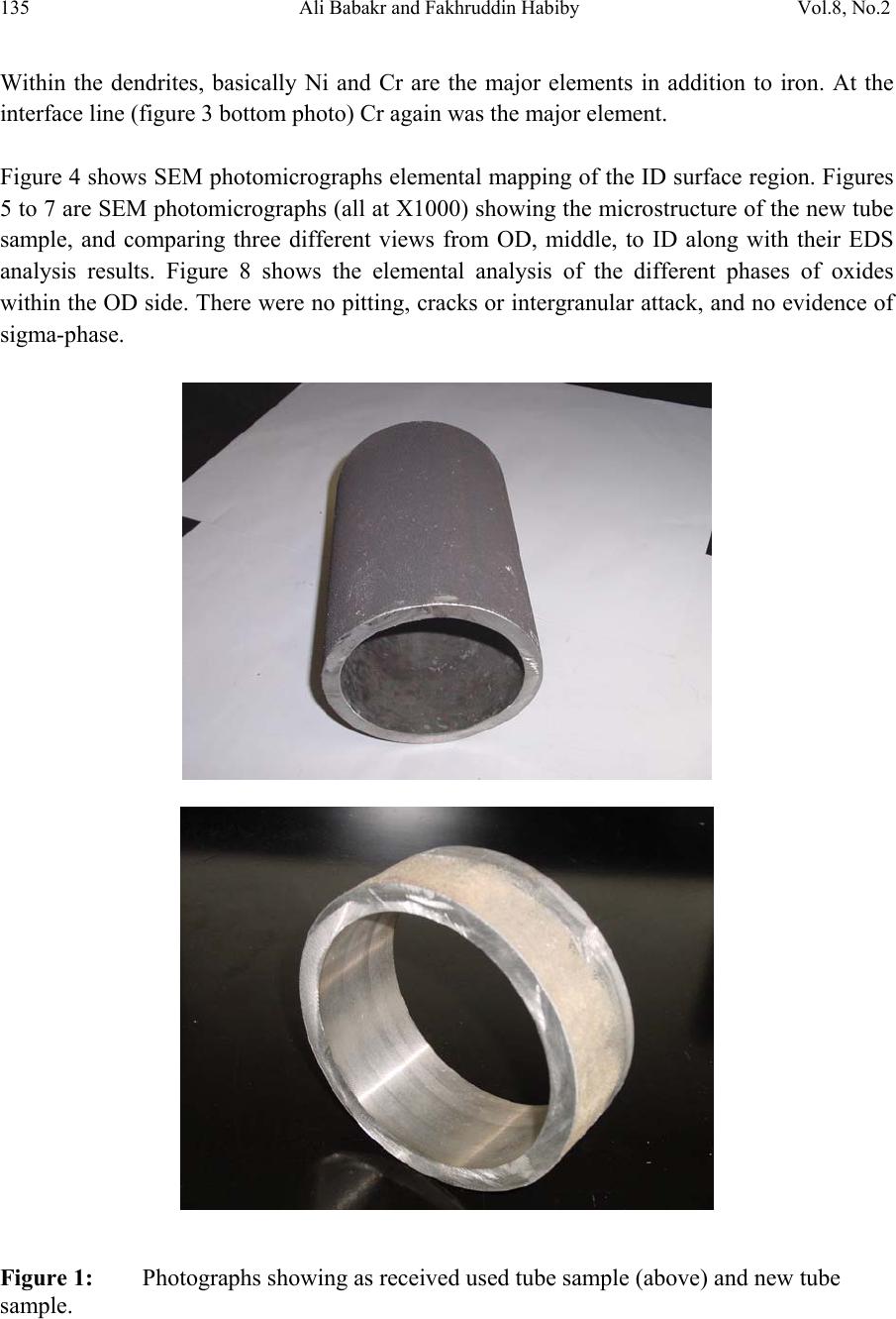 135 Ali Babakr and Fakhruddin Habiby Vol.8, No.2 Within the dendrites, basically Ni and Cr are the major elements in addition to iron. At the interface line (figure 3 bottom photo) Cr again was the major element. Figure 4 shows SEM photomicrographs elemental mapping of the ID surface region. Figures 5 to 7 are SEM photomicrographs (all at X1000) showing the microstructure of the new tube sample, and comparing three different views from OD, middle, to ID along with their EDS analysis results. Figure 8 shows the elemental analysis of the different phases of oxides within the OD side. There were no pitting, cracks or intergranular attack, and no evidence of sigma-phase. Figure 1: Photographs showing as received used tube sample (above) and new tube sample. 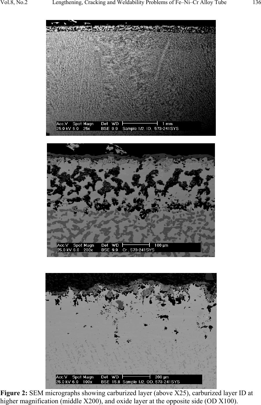 Vol.8, No.2 Lengthening, Cracking and Weldability Problems of Fe–Ni–Cr Alloy Tube 136 Figure 2: SEM micrographs showing carburized layer (above X25), carburized layer ID at higher magnification (middle X200), and oxide layer at the opposite side (OD X100). 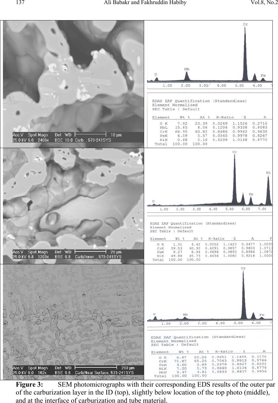 137 Ali Babakr and Fakhruddin Habiby Vol.8, No.2 Figure 3: SEM photomicrographs with their corresponding EDS results of the outer par of the carburization layer in the ID (top ) , s l ightly below location of the top photo (middle), and at the interface of carburization and tube material.  Vol.8, No.2 Lengthening, Cracking and Weldability Problems of Fe–Ni–Cr Alloy Tube 138 Figure 4: SEM photomicrograph elemental mapping of major elements distribution in the carburized layer, Cr (left photo) and (Ni-right photo). 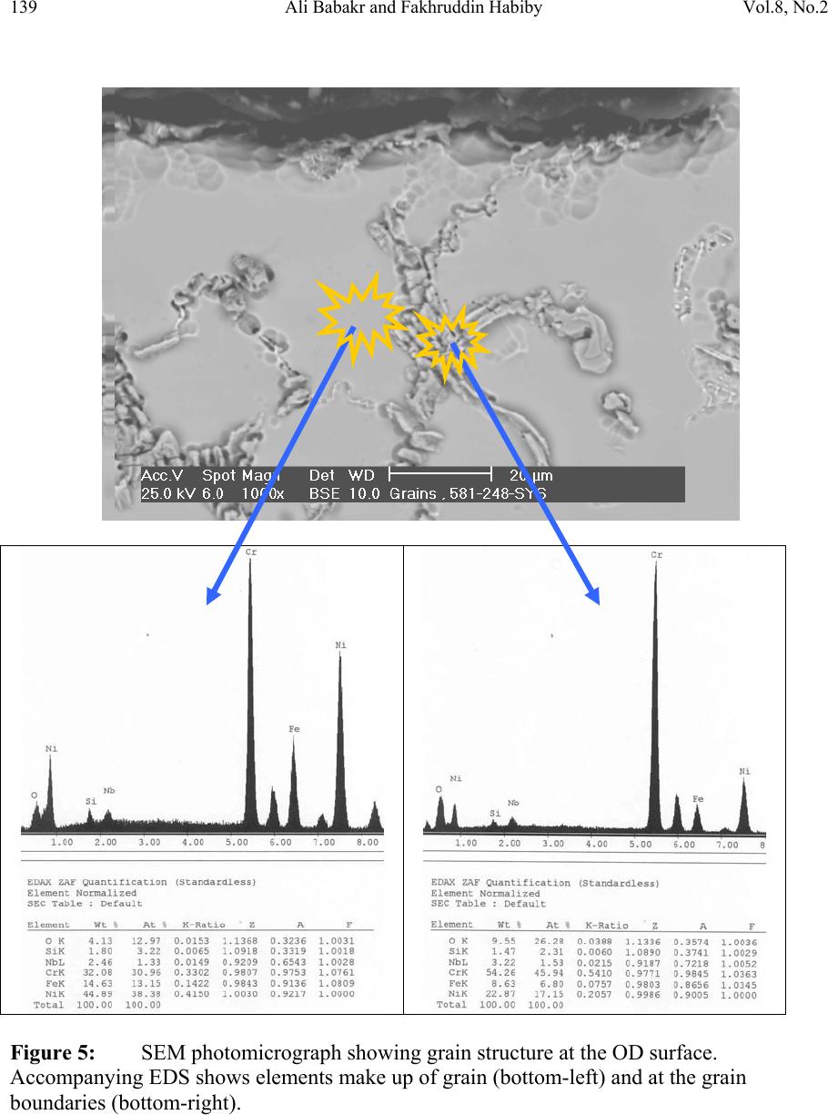 139 Ali Babakr and Fakhruddin Habiby Vol.8, No.2 Figure 5: SEM photomicrograph showing grain structure at the OD surface. Accompanying EDS shows elements make up of grain (bottom-left) and at the grain boundaries (bottom -r ight) . 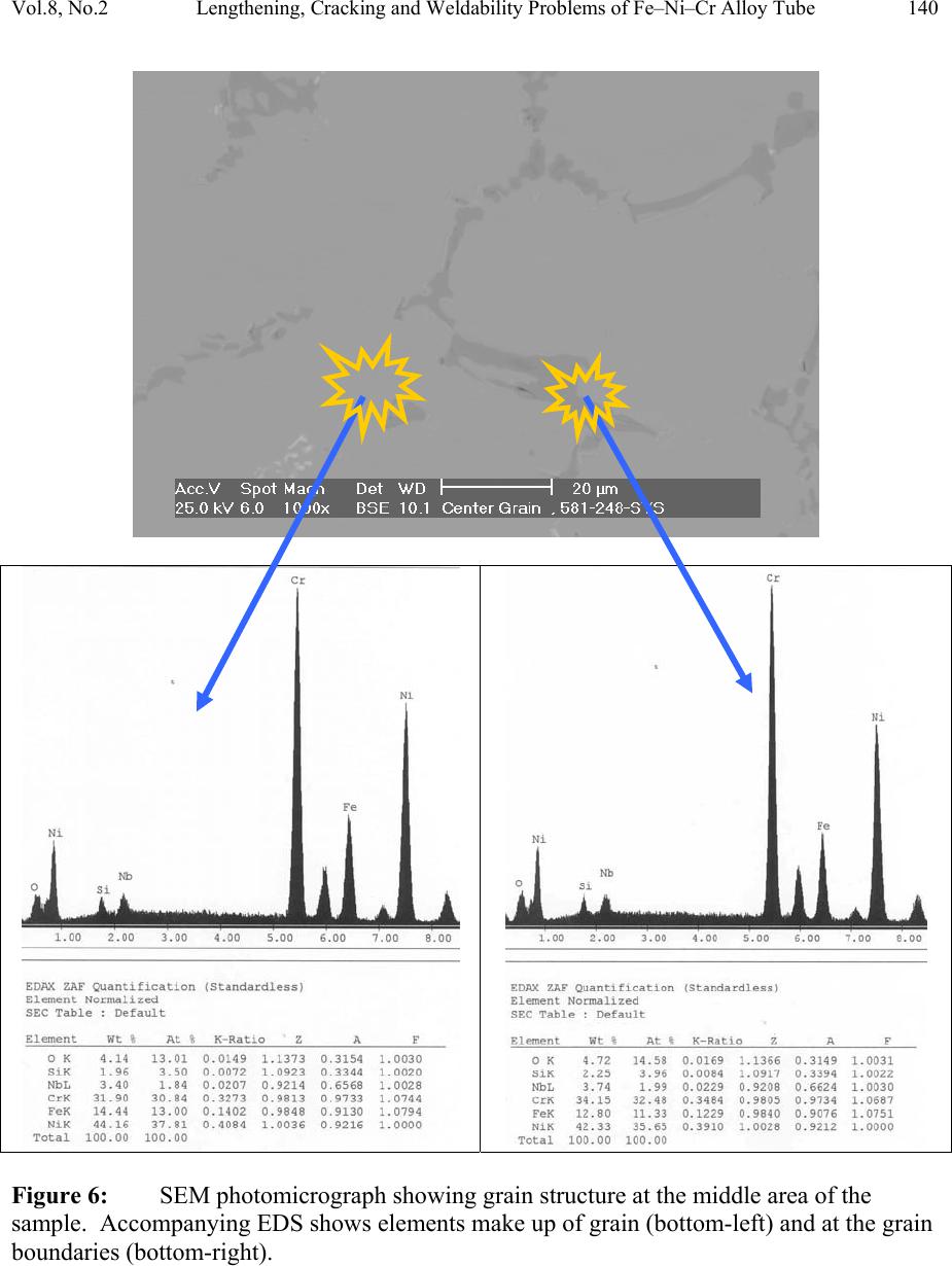 Vol.8, No.2 Lengthening, Cracking and Weldability Problems of Fe–Ni–Cr Alloy Tube 140 Figure 6: SEM photomicrograph showing grain structure at the middle area of the sample. Accompanying EDS shows elements make up of grain (bottom-left) and at the grain boundaries (bottom-right). 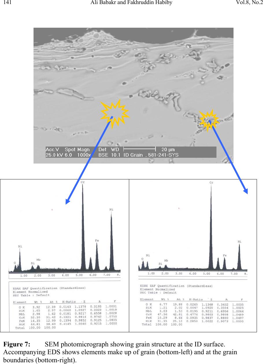 141 Ali Babakr and Fakhruddin Habiby Vol.8, No.2 Figure 7: SEM photomicrograph showing grain structure at the ID surface. Accompanying EDS shows elements make up of grain (bottom-left) and at the grain boundaries (bottom -r ight) .  Vol.8, No.2 Lengthening, Cracking and Weldability Problems of Fe–Ni–Cr Alloy Tube 142 Figure 8: SEM photomicrograph of OD surface showing oxide layer (X300). Oxides could be made up of a mixture of chromium, nickel, niobium, titanium and silicon s u bsurface oxides. 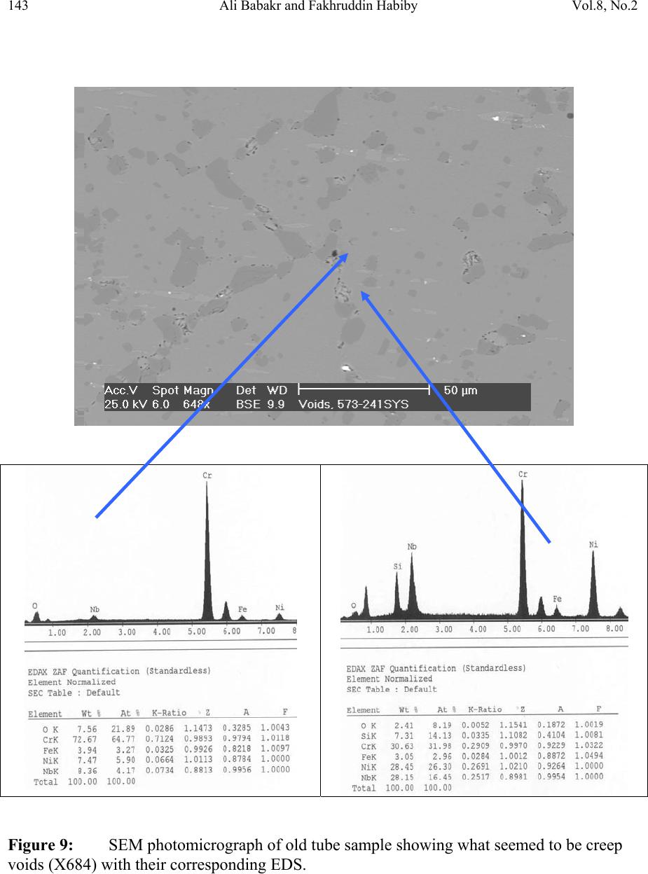 143 Ali Babakr and Fakhruddin Habiby Vol.8, No.2 Figure 9: SEM photomicrograph of old tube sample showing what seemed to be creep voids (X684) with t heir cor resp ond ing EDS.  Vol.8, No.2 Lengthening, Cracking and Weldability Problems of Fe–Ni–Cr Alloy Tube 144 Hardness measurement was performed on two samples taken from both used tube sample and a new (never been used) tube sample. Readings were taken from ID, center, and OD locations. The followin g table summarizes the re sul ts. ID Center OD Used Tube Sample 627 VHN (57 RC) 247 VHN (22 RC) 242 VHN (21 RC) New Tube Sample 529 VHN (51 RC) 342 VHN (35 RC) 342 VHN (35 RC) 3. DISCUSSION Cast austenitic alloys usually have from 5 to 20% ferrite distributed in discontinuous pools throughout the matrix, the percent of ferrite depends on the nickel, chromium, and carbon contents. The presence of ferrite in austenite may be beneficial or detrimental, depending on the application. Chromium (a ferrite and martensite promoter), nickel, and carbon (austenite promoters) are particularly important in determining microstructure. Ferrite can be beneficial in terms of weldability because fully austenitic stainless steels are susceptible to a weldability problem known as hot cracking, or microfissuring (formation of cracks in reheated weld metal regions or parent metal HAZ). The intergranular cracking occurs in the weld deposit and/or in the weld heat-affected zone and can be avoided if the composition of the filler metal is controlled to produce about 4% ferrite in the austenitic weld deposit [13,14]. This is a fact. When the tube sample was magnetically tested, we found that the inner section (ID) was more magnetic than the outer section (OD). There could even be magnetic transition through the cross section for the tube. Assuming this is true, and then the new weld would be of some or no ferrite, which will probably create great difference in thermal conductivities profile. This will promote speedy hot cracking. Generally, solution annealing of the used tube will improve weldability problem; since it will precipitate Cr and C b ack i nt o the g rains. Carburization is a major contributor to longitudinal creep growth and shortening of tube life. As the carbon content increases (in the contact-environment), the creep rate increases dramatically and is accompanied by a reduction in tube life. Carburization is directly affected by alloying elements. For instance, the higher the nickel content is, the lesser is the adsorption of carbon. One aspect of ethylene furnace tubes is that carburization build up is not uniform [15]. The build up rate is usually controlled by diffusion of carbon through pores within the less protective chromia scale or cracks that are formed on its surface due to creep. In isolated situations, if tubes are operated at modest temperatures, these may last 7 to 10 years provided it does not reach 1050°C, such as in the real situation or during decoking [16]. Unfortunately, this do e s n o t re p r e s en t r e al life situation, and it might be exaggerated.  145 Ali Babakr and Fakhruddin Habiby Vol.8, No.2 It was mentioned [17,18] that an optimum nickel to iron ratio of 4 t o 1 was desirable in the minimization of carburization. Three forms of carbides can manifest in a given situation, Cr23C6, Cr7C3, and Cr3C2. The stability of these carbides can be illustrated in figure 10, which ties in the activity of carbon and oxygen of the process. Simply stated, if the activity (aC) of C and O2 intersect or falls in the Cr3C2, then Cr3C2 will form and be more stable on the surface. As carbon diffuses into the alloy, its activity will be lowered and favoring the formation or transformation to Cr7C3 and so on. Other elements (such as Ti, Nb, Mo, Ta and W) within the alloying element family will also form c ar bi de s, figure 11 [18]. Figure 10: Stability diagram of Cr-C-O system at (a) 620°C (1150°F), (b) 870°C (1600°F), and (c) 1090°C (2000°F) [6]. Carbon has a large influence on the mechanical properties of the steel. The decreasing carbon content causes a degradation of these properties, hardness as well as the strength decrease. On the other hand, increasing the carbon level (carburization) increases hardness of the carburized surface; this can be seen from our measurement of ID hardness. Loss of ductility due to carburization is expected. Hence, at a specific site where carburization is not uniform with the rest of the exposed surface, a premature cracking can occur. The orientation of the  Vol.8, No.2 Lengthening, Cracking and Weldability Problems of Fe–Ni–Cr Alloy Tube 146 crack path will be the results of the applied stresses vectors. No two sites are metallurgically compatible. Figure 11: Standard free energy of formation for carbides [6].  147 Ali Babakr and Fakhruddin Habiby Vol.8, No.2 The influence of carburization on the stress profile across the wall of a tube is a complex mechanism. As the metal carbides are formed, a unit volume change takes place, which in itself creates a stress profile. In addition, the carburized layer will have different density and coefficient of thermal expansion. The probable changes in thermal conductivity and thermal expansion cause a change in the overall thermal stresses profile. These are somewhat countered by the significant change in the creep rate of the carburized material. However, their influence is beyond the scope of this investigation. It has been shown [19] through mathematical modeling of a very similar failure that carburization had a major influence on the longitudinal creep extension (lengthening), and decoking time and temperature. In addition, it was suggested that the tubes should retire after approximately three years in service, or at approximately 10% of total length. The factors that have greatest influence on projected tube stress-rupture life are carburization, run length, decoking time and temperature, and the rate of heat up. The rate of carburization and tube lengthening can be said to be a function of process parameters, such as operating and decoking temperatures regimes, and tube location. The general influence on the tubes mechanical behavior can be best studied through correlation of laboratory experiments and the use of mathematical modeling such as FEA. Though, both are plausible, but we believe that the second option is more attainable at this time. Utilization of a selected furnace process operation data can be modeled and simulated for the time in-service of 2 years. 4. CONCLUSION • Weldability problem is most likely due to hot cracking and/or microfissuring, and mostly because of carburization. • The lengthening problem is due to creep activity, which is in the first stage. There were no voids formed in all samples indicating second stage creep. • The tube sample provided showed 25% carburization. • Since there were no cracks in the present sample, nor an actual cracked weld provided, we can only provide a hypothesis. Previous circumferential cracking is suspected to be attributed to mixed stresses produced due to thermally gradient (flux, conductivities differences, etc), formation of carburization and mechanical (lengthening). • For weldability problem, o See the possibility of solution annealing the used tubes for carbide re- stabilization of original grain structures, or even a section of the tube where is going to be welded. This will restore the material to its original condition. • For Lengthening & circumferential crack problems:  Vol.8, No.2 Lengthening, Cracking and Weldability Problems of Fe–Ni–Cr Alloy Tube 148 o Every time there is a chance, it is important to measure length of, pre-selected in service, tube(s) at intervals to form a clear picture of lengthening rate. o Mathematical modeling (FEA) to establish the influence of different operational parameters and changes may have on the performance of 35Cr- 45Ni. The firebox may be included. Mathematical modeling should be able to provide understanding of lengthening profile. This will further the understanding of the mechanical behavior of the tubes within the plant. REFERENCES 1. MAEDA, T., and TERWIJN, F.X., Corrosion 2007, 07419. 2. SCHÜTZE, M., BERGHOF-HASSELBÄCHER, E., Corrosion 2007, 07425. 3. WU, X. Q., YANG, Y. S., ZHAN, W. Y. H. Q., AND HU, Z. Q, J. Mat. Sci., 35 (2000), 855. 4. TOMASZEWICZ, P., JACKSON, P. R. S., TRIMM, P. R. S., AND YOUNG, D. J., J. Mat. Sci., 20, (1985), 482. 5. SOLBERG, J. K., THON, H., Met. Trans. A, v. 14 (1983),1213, 6. JOOS, O, MOLINS, R., FURTADO, J., WASTIAUX, S., Corrosion 2007, 07426. 7. JASKE, C. E., Corrosion 2003, 05419. 8. HAMATANI H., ICHIYAMA Y., AND KOBAYASHI J. Sci. & Tech of Adv. Mat., v. 3 (2002), 319. 9. ROWE M. D., CROOK P., HOBACK G. L., Wel. J., vol.82, (2003), 313. 10. YUE-CHANG, Z., HIROJI, N., FUKUHISA, M., Trans. of JWRI, v. 14, (1985), 313. 11. KAZUTOSHI, N., KAZUYUKI, S., TAKAHASHI, I., MAKOTO, T., Preprints of the National Meeting of J.W.S., 1999, 364. 12. NACE Standard TM 0498-98-Item No. 21235. 13. HELANDER, T., ANDERSON, H.C., AND OSKARSSON, M., Mat. at High temp., v.17(2000), 389. 14. HYDE, T.H., SUN, W., AND WILLIAMS, J.A., Mat. at High temp., v.16 (1999), 117. 15. TILLACK, D.J. AND GUTHRIE, J. E., NIDI Tech. Ser. #10071. 16. GRABKE, H. J., Mat. at High temp., 17 (2000) p483. 17. MINLER, R., AND PHANEUF, M.W., Corrosion 1992, 431. 18. LAI, G.Y., ASM International, 1990. 19. HENDRIX, D.E. AND CLARK, M., Corrosion 1985, 25. |