Paper Menu >>
Journal Menu >>
 Journal of Minerals & Materials Characterization & Engineering, Vol. 8, No.1, pp 25-36, 2009 jmmce.org Printed in the USA. All rights reserved Role of Temperature and Carbon Nanotube Reinforcement on Epoxy based Nanocomposites Subhranshu Sekhar Samal Centre for Nanoscience & Nanotechnology (A joint initiative of IGCAR, Kalpakkam & Sathyabama University, Chennai) India-600119 E-mail: sekhar_nitrkl@rediffmail.com, Cell: +91-9962369727 Abstract: This paper presents the synthesis of epoxy based Multiwalled Carbon nanotubes (MWCNTs) reinforced composites by method of sonication. The variation in the nature of reinforcement (Aligned & Randomly oriented MWNTS) has resulted in the improvement of mechanical properties like flexural modulus, tensile strength and hardness. A small change in chemical treatment of the nanotubes has a great effect in the mechanical and morphological properties of nanocomposites due to effective load transfer mechanism and state of dispersion. The change in properties has been verified by optical microscopy and Scanning electron microscopy. Apart from that the prepared composites has been treated under different temperatures (like hot water, room temperature and liquid nitrogen temperature) and the change in mechanical as well as morphological nature has been verified by SEM of Fractographic surface this proved the elasticity and ductility of the composites. Key Words: MWNT/Reinforcement/Dispersion//Load transfer/SEM 1. INTRODUCTION The discoveries of carbon nanotubes (CNT) have initiated researches in many different areas; one of the most intriguing applications of CNT is the polymer/CNT nanocomposites [1-5]. The high mechanical, electrical and thermal property of CNTs make them ideal candidate as fillers in lightweight polymer composite [6]. Due to their high specific strength and stiffness, nanotube-reinforced polymer composites have become attractive structural materials not only in the weight-sensitive aerospace industry, but also in the marine, armor, automobile, railway, civil engineering structures, and sporting goods industries. Epoxy resin is the polymer matrix used most often with reinforcing nanotubes for advanced composite applications. The resins 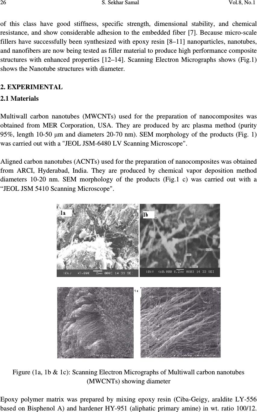 26 S. Sekhar Samal Vol.8, No.1 of this class have good stiffness, specific strength, dimensional stability, and chemical resistance, and show considerable adhesion to the embedded fiber [7]. Because micro-scale fillers have successfully been synthesized with epoxy resin [8–11] nanoparticles, nanotubes, and nanofibers are now being tested as filler material to produce high performance composite structures with enhanced properties [12–14]. Scanning Electron Micrographs shows (Fig.1) shows the Nanotube structures with diameter. 2. EXPERIMENTAL 2.1 Materials Multiwall carbon nanotubes (MWCNTs) used for the preparation of nanocomposites was obtained from MER Corporation, USA. They are produced by arc plasma method (purity 95%, length 10-50 µm and diameters 20-70 nm). SEM morphology of the products (Fig. 1) was carried out with a "JEOL JSM-6480 LV Scanning Microscope". Aligned carbon nanotubes (ACNTs) used for the preparation of nanocomposites was obtained from ARCI, Hyderabad, India. They are produced by chemical vapor deposition method diameters 10-20 nm. SEM morphology of the products (Fig.1 c) was carried out with a “JEOL JSM 5410 Scanning Microscope". Figure (1a, 1b & 1c): Scanning Electron Micrographs of Multiwall carbon nanotubes (MWCNTs) showing diameter Epoxy polymer matrix was prepared by mixing epoxy resin (Ciba-Geigy, araldite LY-556 based on Bisphenol A) and hardener HY-951 (aliphatic primary amine) in wt. ratio 100/12. 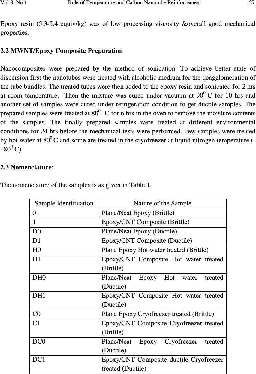 Vol.8, No.1 Role of Temperature and Carbon Nanotube Reinforcement 27 Epoxy resin (5.3-5.4 equiv/kg) was of low processing viscosity &overall good mechanical properties. 2.2 MWNT/Epoxy Composite Preparation Nanocomposites were prepared by the method of sonication. To achieve better state of dispersion first the nanotubes were treated with alcoholic medium for the deagglomeration of the tube bundles. The treated tubes were then added to the epoxy resin and sonicated for 2 hrs at room temperature. Then the mixture was cured under vacuum at 90 0 C for 10 hrs and another set of samples were cured under refrigeration condition to get ductile samples. The prepared samples were treated at 80 0 C for 6 hrs in the oven to remove the moisture contents of the samples. The finally prepared samples were treated at different environmental conditions for 24 hrs before the mechanical tests were performed. Few samples were treated by hot water at 80 0 C and some are treated in the cryofreezer at liquid nitrogen temperature (- 180 0 C). 2.3 Nomenclature: The nomenclature of the samples is as given in Table.1. Sample Identification Nature of the Sample 0 Plane/Neat Epoxy (Brittle) 1 Epoxy/CNT Composite (Brittle) D0 Plane/Neat Epoxy (Ductile) D1 Epoxy/CNT Composite (Ductile) H0 Plane Epoxy Hot water treated (Brittle) H1 Epoxy/CNT Composite Hot water treated (Brittle) DH0 Plane/Neat Epoxy Hot water treated (Ductile) DH1 Epoxy/CNT Composite Hot water treated (Ductile) C0 Plane Epoxy Cryofreezer treated (Brittle) C1 Epoxy/CNT Composite Cryofreezer treated (Brittle) DC0 Plane/Neat Epoxy Cryofreezer treated (Ductile) DC1 Epoxy/CNT Composite ductile Cryofreezer treated (Ductile)  28 S. Sekhar Samal Vol.8, No.1 2.4 Flexural & Tensile Modulus Test 2.4.1 Flexural test & tensile test Four types of flexural test samples were fabricated: they were pure epoxy beam & its ductile one and the nanotube composite beam & its ductile one. The beams were placed into different temperature environments for 24 hours prior the test, these were: (a) room temperature (20 0 C), (b) warm water (80 0 C) and (c) liquid nitrogen (-180 0 C). From each sample, five rectangular specimens were taken for three-point bend test as per ASTM D790 (width=2.7cm, thickness=0.7cm, span=11.2cm, length=12cm). Flexural tests were carried out at ambient temperature using Instron-1195 keeping the cross-head speed 2 mm/min. Flexural modulus of each sample was determined from the average value of five specimens. The samples were made in the form of dog bone shape as shown (Fig.2) and the testings were carried out carried out with INSTRON-1195. Tensile tests were carried out at room temperature with a constant cross-head rate of 2 mm/min. The choice of this quite low loading rate is to consider the brittle character of composites .Ten specimens were tested for each sample and the average value was obtained from the data of these measured specimens (Fig.2). The thickness of samples is 3 mm ± 0.5 mm. Figure 2: Dog Bone Shape sample for tensile modulus measurement. 2.4.2 Flexural measurements Flexural modulus of pure resin, RCNT composite & ACNT composite are shown in Fig.7a. Both the composite samples are showing greater modulus than pure resin sample that is attributed to the high mechanical strength of Composite sample. 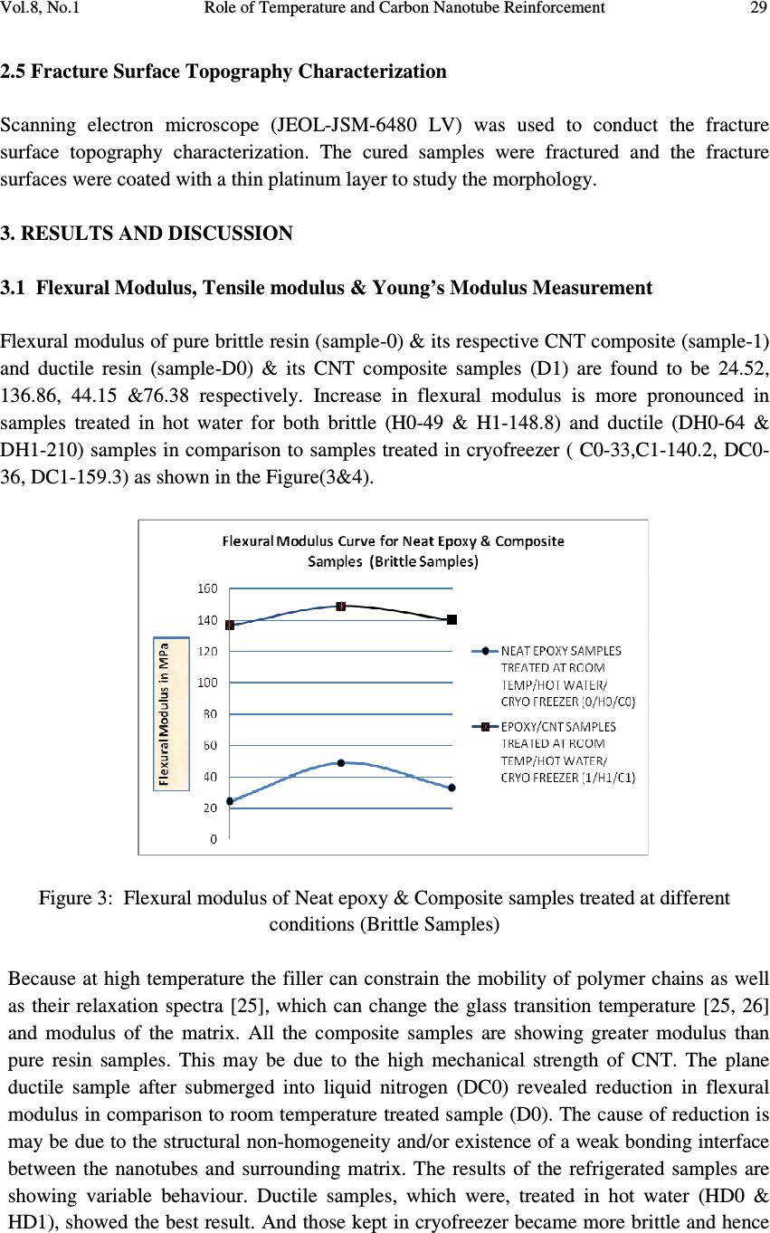 Vol.8, No.1 Role of Temperature and Carbon Nanotube Reinforcement 29 2.5 Fracture Surface Topography Characterization Scanning electron microscope (JEOL-JSM-6480 LV) was used to conduct the fracture surface topography characterization. The cured samples were fractured and the fracture surfaces were coated with a thin platinum layer to study the morphology. 3. RESULTS AND DISCUSSION 3.1 Flexural Modulus, Tensile modulus & Young’s Modulus Measurement Flexural modulus of pure brittle resin (sample-0) & its respective CNT composite (sample-1) and ductile resin (sample-D0) & its CNT composite samples (D1) are found to be 24.52, 136.86, 44.15 &76.38 respectively. Increase in flexural modulus is more pronounced in samples treated in hot water for both brittle (H0-49 & H1-148.8) and ductile (DH0-64 & DH1-210) samples in comparison to samples treated in cryofreezer ( C0-33,C1-140.2, DC0- 36, DC1-159.3) as shown in the Figure(3&4). Figure 3: Flexural modulus of Neat epoxy & Composite samples treated at different conditions (Brittle Samples) Because at high temperature the filler can constrain the mobility of polymer chains as well as their relaxation spectra [25], which can change the glass transition temperature [25, 26] and modulus of the matrix. All the composite samples are showing greater modulus than pure resin samples. This may be due to the high mechanical strength of CNT. The plane ductile sample after submerged into liquid nitrogen (DC0) revealed reduction in flexural modulus in comparison to room temperature treated sample (D0). The cause of reduction is may be due to the structural non-homogeneity and/or existence of a weak bonding interface between the nanotubes and surrounding matrix. The results of the refrigerated samples are showing variable behaviour. Ductile samples, which were, treated in hot water (HD0 & HD1), showed the best result. And those kept in cryofreezer became more brittle and hence 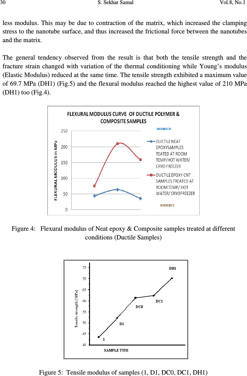 30 S. Sekhar Samal Vol.8, No.1 less modulus. This may be due to contraction of the matrix, which increased the clamping stress to the nanotube surface, and thus increased the frictional force between the nanotubes and the matrix. The general tendency observed from the result is that both the tensile strength and the fracture strain changed with variation of the thermal conditioning while Young’s modulus (Elastic Modulus) reduced at the same time. The tensile strength exhibited a maximum value of 69.7 MPa (DH1) (Fig.5) and the flexural modulus reached the highest value of 210 MPa (DH1) too (Fig.4). Figure 4: Flexural modulus of Neat epoxy & Composite samples treated at different conditions (Ductile Samples) Figure 5: Tensile modulus of samples (1, D1, DC0, DC1, DH1) 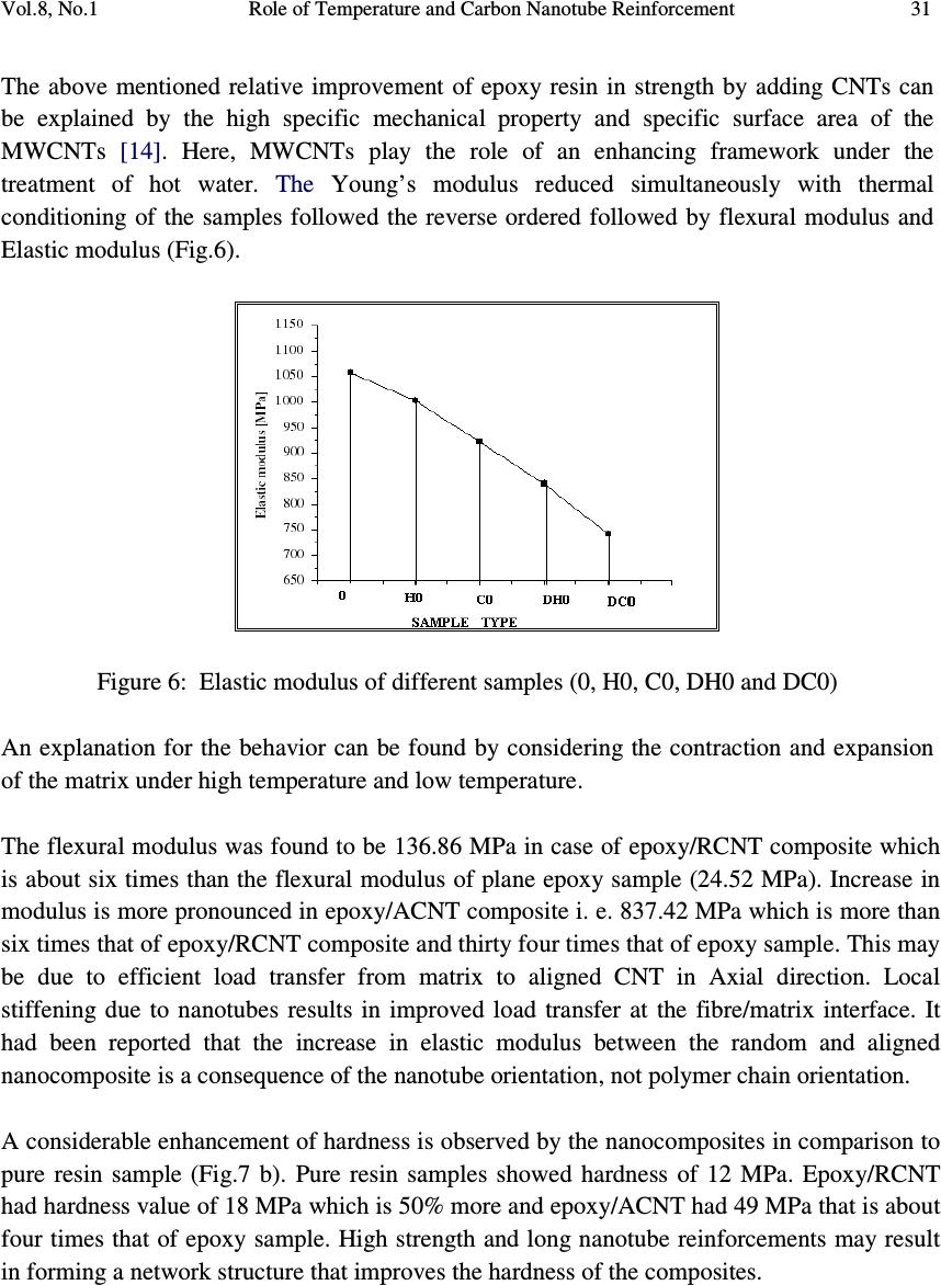 Vol.8, No.1 Role of Temperature and Carbon Nanotube Reinforcement 31 The above mentioned relative improvement of epoxy resin in strength by adding CNTs can be explained by the high specific mechanical property and specific surface area of the MWCNTs [14]. Here, MWCNTs play the role of an enhancing framework under the treatment of hot water. The Young’s modulus reduced simultaneously with thermal conditioning of the samples followed the reverse ordered followed by flexural modulus and Elastic modulus (Fig.6). Figure 6: Elastic modulus of different samples (0, H0, C0, DH0 and DC0) An explanation for the behavior can be found by considering the contraction and expansion of the matrix under high temperature and low temperature. The flexural modulus was found to be 136.86 MPa in case of epoxy/RCNT composite which is about six times than the flexural modulus of plane epoxy sample (24.52 MPa). Increase in modulus is more pronounced in epoxy/ACNT composite i. e. 837.42 MPa which is more than six times that of epoxy/RCNT composite and thirty four times that of epoxy sample. This may be due to efficient load transfer from matrix to aligned CNT in Axial direction. Local stiffening due to nanotubes results in improved load transfer at the fibre/matrix interface. It had been reported that the increase in elastic modulus between the random and aligned nanocomposite is a consequence of the nanotube orientation, not polymer chain orientation. A considerable enhancement of hardness is observed by the nanocomposites in comparison to pure resin sample (Fig.7 b). Pure resin samples showed hardness of 12 MPa. Epoxy/RCNT had hardness value of 18 MPa which is 50% more and epoxy/ACNT had 49 MPa that is about four times that of epoxy sample. High strength and long nanotube reinforcements may result in forming a network structure that improves the hardness of the composites. 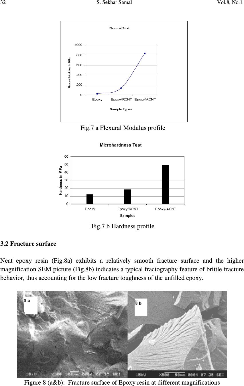 32 S. Sekhar Samal Vol.8, No.1 Fig.7 a Flexural Modulus profile Fig.7 b Hardness profile 3.2 Fracture surface Neat epoxy resin (Fig.8a) exhibits a relatively smooth fracture surface and the higher magnification SEM picture (Fig.8b) indicates a typical fractography feature of brittle fracture behavior, thus accounting for the low fracture toughness of the unfilled epoxy. Figure 8 (a&b): Fracture surface of Epoxy resin at different magnifications 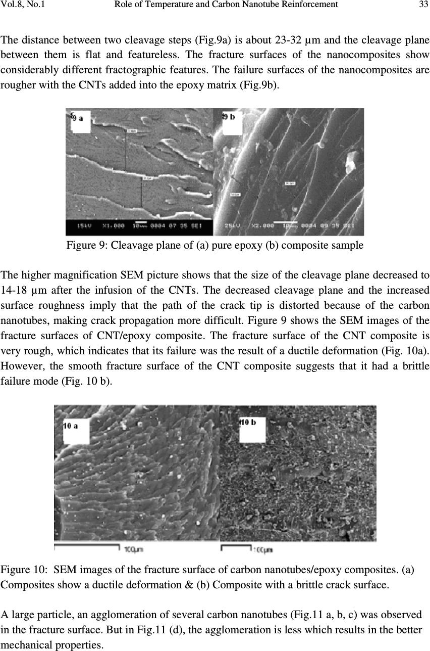 Vol.8, No.1 Role of Temperature and Carbon Nanotube Reinforcement 33 The distance between two cleavage steps (Fig.9a) is about 23-32 µm and the cleavage plane between them is flat and featureless. The fracture surfaces of the nanocomposites show considerably different fractographic features. The failure surfaces of the nanocomposites are rougher with the CNTs added into the epoxy matrix (Fig.9b). Figure 9: Cleavage plane of (a) pure epoxy (b) composite sample The higher magnification SEM picture shows that the size of the cleavage plane decreased to 14-18 µm after the infusion of the CNTs. The decreased cleavage plane and the increased surface roughness imply that the path of the crack tip is distorted because of the carbon nanotubes, making crack propagation more difficult. Figure 9 shows the SEM images of the fracture surfaces of CNT/epoxy composite. The fracture surface of the CNT composite is very rough, which indicates that its failure was the result of a ductile deformation (Fig. 10a). However, the smooth fracture surface of the CNT composite suggests that it had a brittle failure mode (Fig. 10 b). Figure 10: SEM images of the fracture surface of carbon nanotubes/epoxy composites. (a) Composites show a ductile deformation & (b) Composite with a brittle crack surface. A large particle, an agglomeration of several carbon nanotubes (Fig.11 a, b, c) was observed in the fracture surface. But in Fig.11 (d), the agglomeration is less which results in the better mechanical properties. 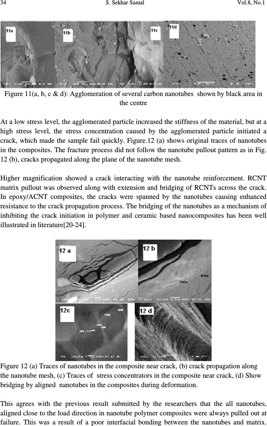 34 S. Sekhar Samal Vol.8, No.1 Figure 11(a, b, c & d): Agglomeration of several carbon nanotubes shown by black area in the centre At a low stress level, the agglomerated particle increased the stiffness of the material, but at a high stress level, the stress concentration caused by the agglomerated particle initiated a crack, which made the sample fail quickly. Figure.12 (a) shows original traces of nanotubes in the composites. The fracture process did not follow the nanotube pullout pattern as in Fig. 12 (b), cracks propagated along the plane of the nanotube mesh. Higher magnification showed a crack interacting with the nanotube reinforcement. RCNT matrix pullout was observed along with extension and bridging of RCNTs across the crack. In epoxy/ACNT composites, the cracks were spanned by the nanotubes causing enhanced resistance to the crack propagation process. The bridging of the nanotubes as a mechanism of inhibiting the crack initiation in polymer and ceramic based nanocomposites has been well illustrated in literature[20-24]. Figure 12 (a) Traces of nanotubes in the composite near crack, (b) crack propagation along the nanotube mesh, (c) Traces of stress concentrators in the composite near crack, (d) Show bridging by aligned nanotubes in the composites during deformation. This agrees with the previous result submitted by the researchers that the all nanotubes, aligned close to the load direction in nanotube polymer composites were always pulled out at failure. This was a result of a poor interfacial bonding between the nanotubes and matrix. 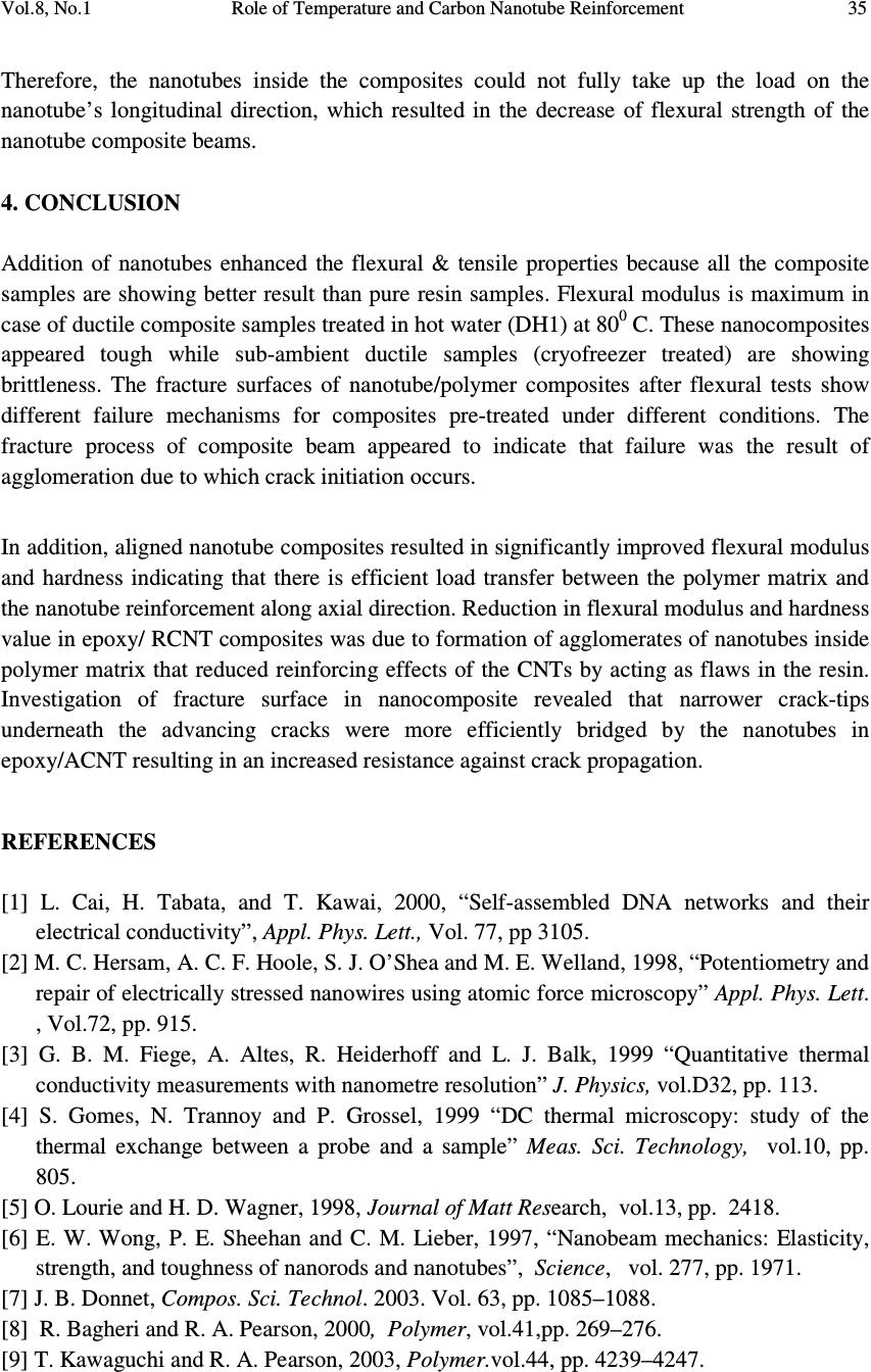 Vol.8, No.1 Role of Temperature and Carbon Nanotube Reinforcement 35 Therefore, the nanotubes inside the composites could not fully take up the load on the nanotube’s longitudinal direction, which resulted in the decrease of flexural strength of the nanotube composite beams. 4. CONCLUSION Addition of nanotubes enhanced the flexural & tensile properties because all the composite samples are showing better result than pure resin samples. Flexural modulus is maximum in case of ductile composite samples treated in hot water (DH1) at 80 0 C. These nanocomposites appeared tough while sub-ambient ductile samples (cryofreezer treated) are showing brittleness. The fracture surfaces of nanotube/polymer composites after flexural tests show different failure mechanisms for composites pre-treated under different conditions. The fracture process of composite beam appeared to indicate that failure was the result of agglomeration due to which crack initiation occurs. In addition, aligned nanotube composites resulted in significantly improved flexural modulus and hardness indicating that there is efficient load transfer between the polymer matrix and the nanotube reinforcement along axial direction. Reduction in flexural modulus and hardness value in epoxy/ RCNT composites was due to formation of agglomerates of nanotubes inside polymer matrix that reduced reinforcing effects of the CNTs by acting as flaws in the resin. Investigation of fracture surface in nanocomposite revealed that narrower crack-tips underneath the advancing cracks were more efficiently bridged by the nanotubes in epoxy/ACNT resulting in an increased resistance against crack propagation. REFERENCES [1] L. Cai, H. Tabata, and T. Kawai, 2000, “Self-assembled DNA networks and their electrical conductivity”, Appl. Phys. Lett., Vol. 77, pp 3105. [2] M. C. Hersam, A. C. F. Hoole, S. J. O’Shea and M. E. Welland, 1998, “Potentiometry and repair of electrically stressed nanowires using atomic force microscopy” Appl. Phys. Lett. , Vol.72, pp. 915. [3] G. B. M. Fiege, A. Altes, R. Heiderhoff and L. J. Balk, 1999 “Quantitative thermal conductivity measurements with nanometre resolution” J. Physics, vol.D32, pp. 113. [4] S. Gomes, N. Trannoy and P. Grossel, 1999 “DC thermal microscopy: study of the thermal exchange between a probe and a sample” Meas. Sci. Technology, vol.10, pp. 805. [5] O. Lourie and H. D. Wagner, 1998, Journal of Matt Research, vol.13, pp. 2418. [6] E. W. Wong, P. E. Sheehan and C. M. Lieber, 1997, “Nanobeam mechanics: Elasticity, strength, and toughness of nanorods and nanotubes”, Science, vol. 277, pp. 1971. [7] J. B. Donnet, Compos. Sci. Technol. 2003. Vol. 63, pp. 1085–1088. [8] R. Bagheri and R. A. Pearson, 2000, Polymer, vol.41,pp. 269–276. [9] T. Kawaguchi and R. A. Pearson, 2003, Polymer.vol.44, pp. 4239–4247.  36 S. Sekhar Samal Vol.8, No.1 [10] H. Mahfuz, A. Adnan, V. K. Rangari, S. Jeelani and B. Z. Jang, 2004, Compos. Part A: Appl. Sci. Manuf., vol. 35, pp. 519–527. [11] M. F. Evora and A. Shukla, 2003, Mater Sci. Engg.A, vol.361, pp. 358–366 [12] R. Rodgers, H. Mahfuz, V. Rangari, N. Chisholm and S. Jeelani, 2005, Macromol. Mater. Engg, vol. 290, pp. 423–429. [13] P. Farhana, Y.X. Zhou, V. Rangari and S. Jeelani, 2005 Mater. Sci. Eng. A, vol. 405 (1– 2), pp. 246–253. [14] Y. H. Liao, M. T. Olivier, Z. Y. Liang, C. Zhang and B. Wang, 2004, Mater. Sci. Eng.A, vol.385, pp. 175–181. [15] C. G. Zhao, G. J. Hu, R. Justice, D. W. Schaefer, S. Zhang, M. S. Yang and C. C. Han, 2005, Polymer, vol. 46, pp. 5125–5132. [16] S. Kim, T. W. Pechar, E. Marand, 2006, Desalination, vol.192, pp. 330–339. [17] H. Cai, F. Y. Yan and Q. J. Xue, 2004, Mater. Sci. Eng. vol. 364, pp 94–100. [18] T. Ogasawara, Y. Ishida, T. Ishikawa and R. Yokota, 2004, Compos. Part A: Appl.Sci. Manuf, vol.35, pp. 67–74. [19] F.H. Gojny, J. Nastalczyk, Z. Roslaniec and K. Schulte, 2003, Chem. Phys. Lett., vol. 370, pp 820–824. [20] H. Koerner, W. D. Liu, M. Alexander, P. Mirau, H. Dowty and R. A. Vaia, 2005, Polymer, Vol.46, pp. 4405–4420. [21] H. C. Kuan, C. M. Ma, W. P. Chang, S. M. Yuen, H. H. Wu and T. M. Lee, 2005 Compos. Sci. Technology, vol. 65, pp. 1703–1710. [22] M. K. Seo and S. J. Park, 2004, Chem. Phys. Lett., vol. 395, pp. 44–48. [23] C. S. Li, T. X. Liang, W. Z. Lu, C. H. Tang, X. Q. Hu, M. S. Cao and J. Liang, 2004, Compos. Sci. Technology, vol.64, pp 2089–2096. [24] M. K. Seo, J. R. Lee and S. J. Park, 2005 Mater. Sci. Eng. A, vol. 404, pp 79–84. [25] J. Baschnagul, K. Binder, 1999, MRS symposium. Proceeding,Vol. 543, pp. 157-164. [26] F.R Sherliker, 1998, polymer Journal, vol.12, pp.88. |