Paper Menu >>
Journal Menu >>
 Journal of Minerals & Materials Characterization & Engineering, Vol. 7, No.3, pp 233-245, 2008 jmmce.org Printed in the USA. All rights reserved 233 Working Properties of Some Selected Refractory Clay Deposits in South Western Nigeria J.A. Omotoyinbo 1 and O.O.Oluwole 2* 1 Metallurgical and Materials Engineering Dept.,FUT, Akure, Nigeria 2 Materials Science and Engineering Dept., OAU,Ile-ife, Nigeria *Dr O.Oluwole. Obafemi Awolowo University, Ileife +2348033899701 e-mail: leke_oluwole@yahoo.co.uk ABSTRACT Working properties of some clay deposits in Ekiti State, Nigeria were investigated with a view to determine their suitability for use as refractory bricks. The samples were collected from three different commercial pottery clay centers in Ekiti State; they are Ara, Awo and Isan. Two varieties were collected from both Ara and Isan, which are named Ara 1, Ara 2, and Isan 1, Isan 2 respectively while only one type was collected from Awo. The clay samples were crushed, pulverized, sieved and their chemical compositions were determined. The clay samples were treated separately as well as blended together in different proportions and moulded into bricks. The bricks were dried and fired to 1050 o C. Tests for refractoriness, thermal shock resistance, shrinkage, thermal expansion; bulk density, porosity, and compressive strength were carried out on each batch specimen. The results showed that Ara 2 and Ara 1, 2 combined in equal proportions displayed the highest thermo chemical stability. They also possess comparatively high cold crushing strength, and high thermal shock resistance, but definitely not the highest. The apparent porosity of all the batch specimens was found to be high as well as the bulk densities, while the shrinkage of all the specimens were low. It was concluded that 100% Ara 2, and a blend of Ara 1 and 2 in equal proportions, are most suitable for production of crucibles, and furnace lining for non ferrous metals processing, such as Aluminium, Lead and Bronze. Key words: Refractory clay deposits; thermochemical stability; strength; shock resistance; porosity;  234 J.A. Omotoyinbo and O.O.Oluwole Vol.7, No.3 1. INTRODUCTION A refractory material is one which has the ability to withstand high temperature without breaking of deforming. Refractory products are used wherever high temperatures are required and include refractory bricks for furnace linings, tubes for electric furnaces, crucibles, thermocouple sheaths, refractory cements, among others. The classifications of refractory materials according to their chemical nature are basic, neutral and acid refractories which are discussed exhaustively in literature [1, 2]. The more important characteristics which are required of a refractory are: (a.) High melting point or high refractoriness, which is closely related to thermochemical stability. (b.) Mechanical strength at high temperature in terms of high refractoriness under load, high thermal shock resistance, low thermal shrinkage, low porosity and permeability. (c.) Resistance to chemical attack in the particular situation in which it is used, for instance, high resistance to corrosion by slags. Substantial amount of work has been carried out in the area of production and development of good refractory materials especially in Europe and America for more than two centuries, the results of which gave rise to the myriads of refractory materials available in the world market today. Most developing nations that are consumers of refractory materials, for instance Nigeria, have to spend their hard earn foreign currencies on the importation of these materials to meet their needs. In the light of this situation, there has been a continuous upsurge of interest in the area of the development of good refractories in Nigeria in the last two decades. A number of studies on the thermophysical and thermochemical behavior of some Nigerian refractory raw materials [3-11] are available. Also general details in respect of origin characteristics of clay minerals can be found in literatures [12-17]. Two factors are accentuating the development of good refractories using the local raw materials. The first one is the growing number of metallurgical industries that are in dire need of these refractories, while the other factor is the advent of foreign exchange market, a situation that has led to higher and unaffordable cost of procuring the refractory materials needed by these industries. Some of the refractory materials usually employed are fireclay, quartz sand, magnesite, sillimanite, berylia, alumina, chromite, zirconia, boron, nitride, graphite and carbide. Each of the refractory materials consists of one or more of the following refractory oxides and their respective fusion point indicated in o C; MgO-2800, ZrO 2 -2677, CaO- 2570, BeO-2550, CrO 2 -2275, Al 2 O 3 -2050, BaO-1917, TiO 2 -1850 and SiO 2 -1715 [2]. 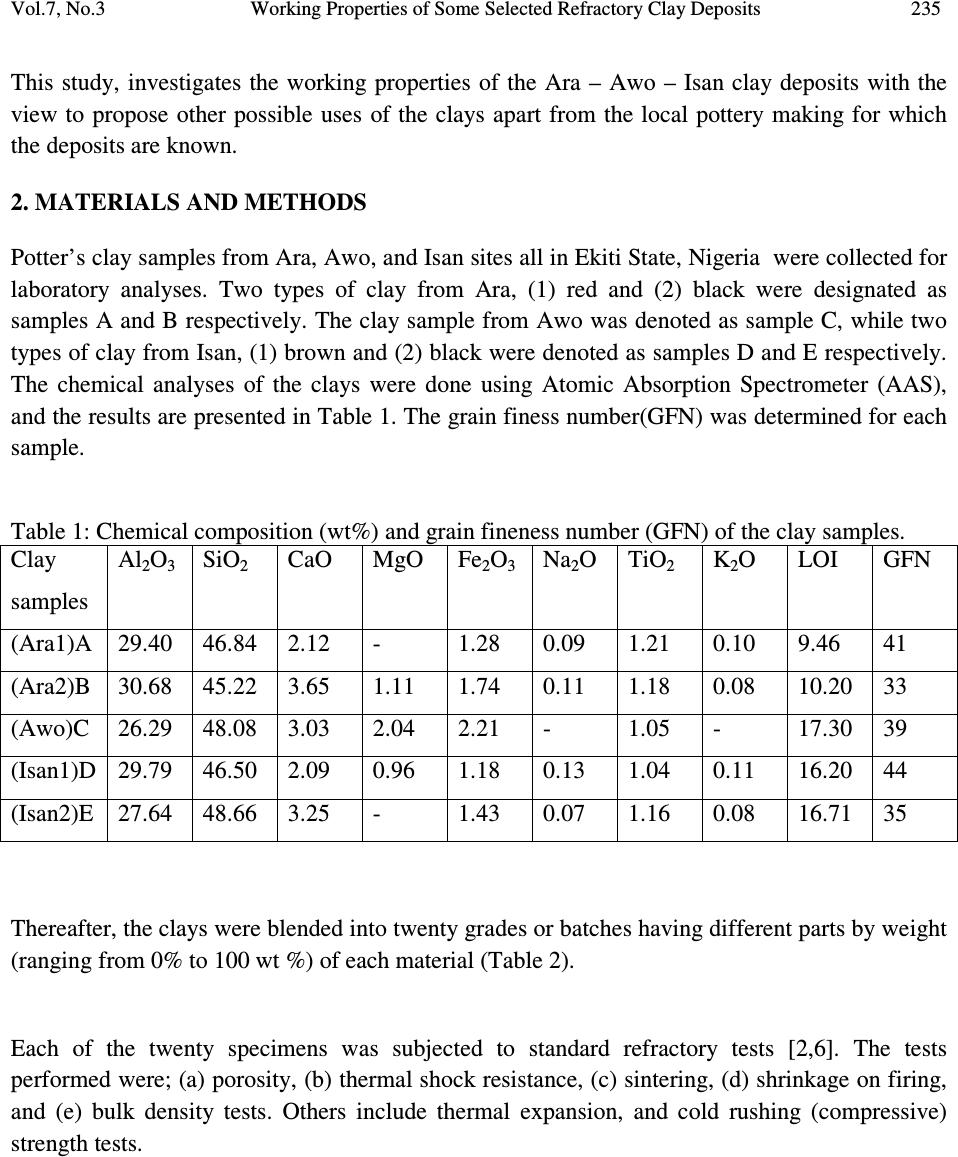 Vol.7, No.3 Working Properties of Some Selected Refractory Clay Deposits 235 This study, investigates the working properties of the Ara – Awo – Isan clay deposits with the view to propose other possible uses of the clays apart from the local pottery making for which the deposits are known. 2. MATERIALS AND METHODS Potter’s clay samples from Ara, Awo, and Isan sites all in Ekiti State, Nigeria were collected for laboratory analyses. Two types of clay from Ara, (1) red and (2) black were designated as samples A and B respectively. The clay sample from Awo was denoted as sample C, while two types of clay from Isan, (1) brown and (2) black were denoted as samples D and E respectively. The chemical analyses of the clays were done using Atomic Absorption Spectrometer (AAS), and the results are presented in Table 1. The grain finess number(GFN) was determined for each sample. Table 1: Chemical composition (wt%) and grain fineness number (GFN) of the clay samples. Clay samples Al 2 O 3 SiO 2 CaO MgO Fe 2 O 3 Na 2 O TiO 2 K 2 O LOI GFN (Ara1)A 29.40 46.84 2.12 - 1.28 0.09 1.21 0.10 9.46 41 (Ara2)B 30.68 45.22 3.65 1.11 1.74 0.11 1.18 0.08 10.20 33 (Awo)C 26.29 48.08 3.03 2.04 2.21 - 1.05 - 17.30 39 (Isan1)D 29.79 46.50 2.09 0.96 1.18 0.13 1.04 0.11 16.20 44 (Isan2)E 27.64 48.66 3.25 - 1.43 0.07 1.16 0.08 16.71 35 Thereafter, the clays were blended into twenty grades or batches having different parts by weight (ranging from 0% to 100 wt %) of each material (Table 2). Each of the twenty specimens was subjected to standard refractory tests [2,6]. The tests performed were; (a) porosity, (b) thermal shock resistance, (c) sintering, (d) shrinkage on firing, and (e) bulk density tests. Others include thermal expansion, and cold rushing (compressive) strength tests. 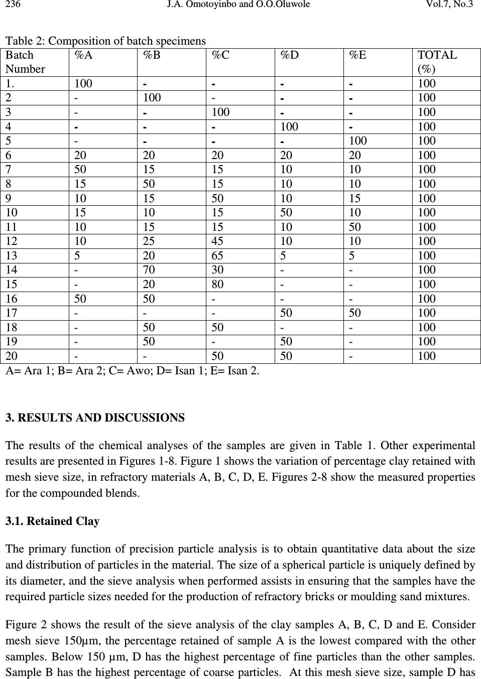 236 J.A. Omotoyinbo and O.O.Oluwole Vol.7, No.3 Table 2: Composition of batch specimens Batch Number %A %B %C %D %E TOTAL (%) 1. 100 - - - - 100 2 - 100 - - - 100 3 - - 100 - - 100 4 - - - 100 - 100 5 - - - - 100 100 6 20 20 20 20 20 100 7 50 15 15 10 10 100 8 15 50 15 10 10 100 9 10 15 50 10 15 100 10 15 10 15 50 10 100 11 10 15 15 10 50 100 12 10 25 45 10 10 100 13 5 20 65 5 5 100 14 - 70 30 - - 100 15 - 20 80 - - 100 16 50 50 - - - 100 17 - - - 50 50 100 18 - 50 50 - - 100 19 - 50 - 50 - 100 20 - - 50 50 - 100 A= Ara 1; B= Ara 2; C= Awo; D= Isan 1; E= Isan 2. 3. RESULTS AND DISCUSSIONS The results of the chemical analyses of the samples are given in Table 1. Other experimental results are presented in Figures 1-8. Figure 1 shows the variation of percentage clay retained with mesh sieve size, in refractory materials A, B, C, D, E. Figures 2-8 show the measured properties for the compounded blends. 3.1. Retained Clay The primary function of precision particle analysis is to obtain quantitative data about the size and distribution of particles in the material. The size of a spherical particle is uniquely defined by its diameter, and the sieve analysis when performed assists in ensuring that the samples have the required particle sizes needed for the production of refractory bricks or moulding sand mixtures. Figure 2 shows the result of the sieve analysis of the clay samples A, B, C, D and E. Consider mesh sieve 150µm, the percentage retained of sample A is the lowest compared with the other samples. Below 150 µm, D has the highest percentage of fine particles than the other samples. Sample B has the highest percentage of coarse particles. At this mesh sieve size, sample D has 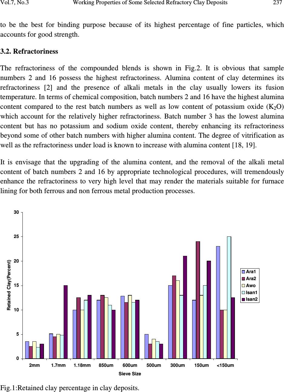 Vol.7, No.3 Working Properties of Some Selected Refractory Clay Deposits 237 to be the best for binding purpose because of its highest percentage of fine particles, which accounts for good strength. 3.2. Refractoriness The refractoriness of the compounded blends is shown in Fig.2. It is obvious that sample numbers 2 and 16 possess the highest refractoriness. Alumina content of clay determines its refractoriness [2] and the presence of alkali metals in the clay usually lowers its fusion temperature. In terms of chemical composition, batch numbers 2 and 16 have the highest alumina content compared to the rest batch numbers as well as low content of potassium oxide (K 2 O) which account for the relatively higher refractoriness. Batch number 3 has the lowest alumina content but has no potassium and sodium oxide content, thereby enhancing its refractoriness beyond some of other batch numbers with higher alumina content. The degree of vitrification as well as the refractoriness under load is known to increase with alumina content [18, 19]. It is envisage that the upgrading of the alumina content, and the removal of the alkali metal content of batch numbers 2 and 16 by appropriate technological procedures, will tremendously enhance the refractoriness to very high level that may render the materials suitable for furnace lining for both ferrous and non ferrous metal production processes. 0 5 10 15 20 25 30 2mm1.7mm1.18mm850um 600um 500um 300um 150um<150um Sieve Size Retained Clay(Percent) Ara1 Ara2 Awo Isan1 Isan2 Fig.1:Retained clay percentage in clay deposits. 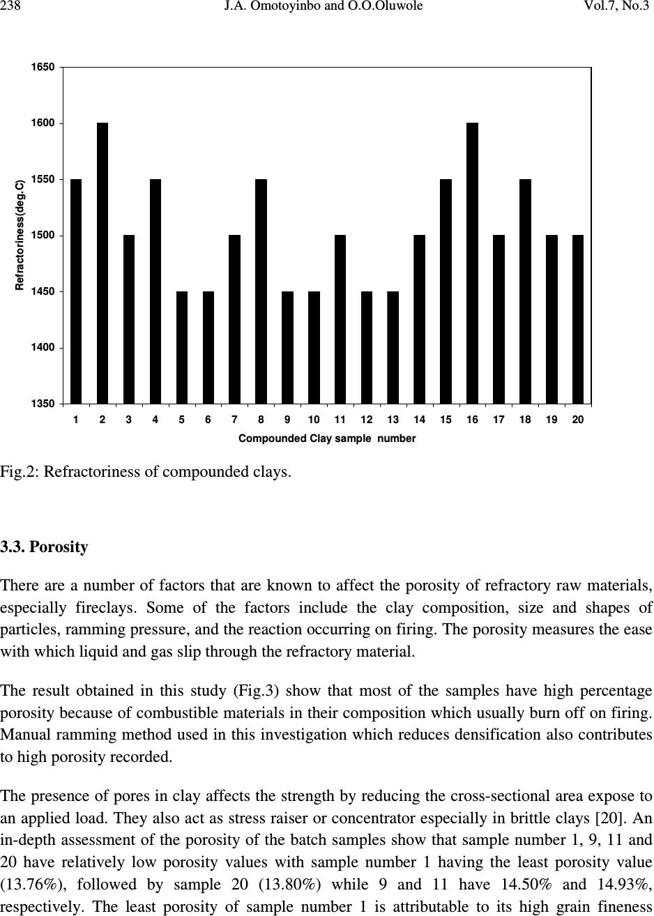 238 J.A. Omotoyinbo and O.O.Oluwole Vol.7, No.3 1350 1400 1450 1500 1550 1600 1650 1 2 3 4 5 6 7 8 91011121314151617181920 Compounded Clay sample number Refractoriness(deg.C) Fig.2: Refractoriness of compounded clays. 3.3. Porosity There are a number of factors that are known to affect the porosity of refractory raw materials, especially fireclays. Some of the factors include the clay composition, size and shapes of particles, ramming pressure, and the reaction occurring on firing. The porosity measures the ease with which liquid and gas slip through the refractory material. The result obtained in this study (Fig.3) show that most of the samples have high percentage porosity because of combustible materials in their composition which usually burn off on firing. Manual ramming method used in this investigation which reduces densification also contributes to high porosity recorded. The presence of pores in clay affects the strength by reducing the cross-sectional area expose to an applied load. They also act as stress raiser or concentrator especially in brittle clays [20]. An in-depth assessment of the porosity of the batch samples show that sample number 1, 9, 11 and 20 have relatively low porosity values with sample number 1 having the least porosity value (13.76%), followed by sample 20 (13.80%) while 9 and 11 have 14.50% and 14.93%, respectively. The least porosity of sample number 1 is attributable to its high grain fineness 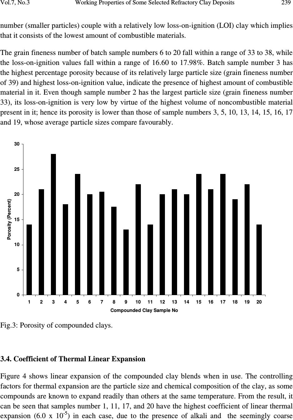 Vol.7, No.3 Working Properties of Some Selected Refractory Clay Deposits 239 number (smaller particles) couple with a relatively low loss-on-ignition (LOI) clay which implies that it consists of the lowest amount of combustible materials. The grain fineness number of batch sample numbers 6 to 20 fall within a range of 33 to 38, while the loss-on-ignition values fall within a range of 16.60 to 17.98%. Batch sample number 3 has the highest percentage porosity because of its relatively large particle size (grain fineness number of 39) and highest loss-on-ignition value, indicate the presence of highest amount of combustible material in it. Even though sample number 2 has the largest particle size (grain fineness number 33), its loss-on-ignition is very low by virtue of the highest volume of noncombustible material present in it; hence its porosity is lower than those of sample numbers 3, 5, 10, 13, 14, 15, 16, 17 and 19, whose average particle sizes compare favourably. 0 5 10 15 20 25 30 12345678910 11 12 13 14 15 16 17 18 19 20 Compounded Clay Sample No Porosity (Percent) Fig.3: Porosity of compounded clays. 3.4. Coefficient of Thermal Linear Expansion Figure 4 shows linear expansion of the compounded clay blends when in use. The controlling factors for thermal expansion are the particle size and chemical composition of the clay, as some compounds are known to expand readily than others at the same temperature. From the result, it can be seen that samples number 1, 11, 17, and 20 have the highest coefficient of linear thermal expansion (6.0 x 10 -5 ) in each case, due to the presence of alkali and the seemingly coarse  240 J.A. Omotoyinbo and O.O.Oluwole Vol.7, No.3 particles of the samples. It is well established that high alkali content favours high thermal expansion which in turn leads to low thermal shock resistance and vice versa. Sample number 15 has the least coefficient of expansion due to the presence of very low alkali which favours very low thermal expansion behaviour. 0 1 2 3 4 5 6 7 1 2 3 4 5 6 7 8 91011121314151617181920 Compounded Clay Sample No Coefficient of Linear Thermal Expansion x 10-5 Fig.4: Coefficient of Linear Thermal Expansion of samples. 3.5. Thermal Shock Resistance The result in Figure 5 gives the approximate number of heat cycle the material could withstood when in use. Thermal shock resistance of a material is influenced by the particle size, coefficient of linear expansion, and thermal conductivity of the material. Refractory materials with low thermal coefficient of expansion and coarse textures have increased resistance to sudden changes in temperature [2]. This accounts for the highest thermal shock resistance exhibited by sample number 15 that is characterized by lowest thermal coefficient of expansion and moderately coarse particle size. Sample number 11 has the lowest thermal shock resistance because of its high thermal coefficient of expansion and fine particle size, And, thus the low resistance to sudden change in temperature. 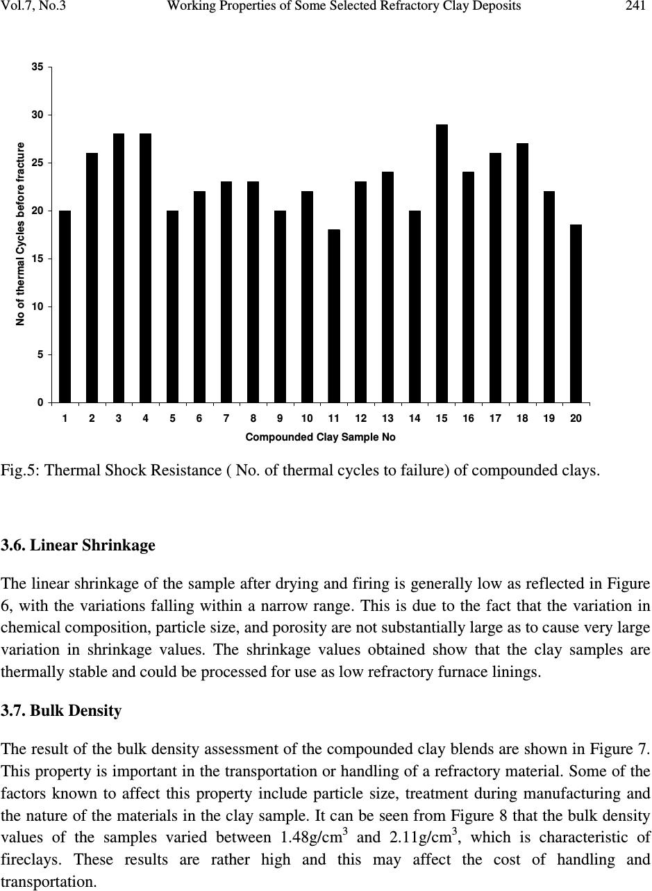 Vol.7, No.3 Working Properties of Some Selected Refractory Clay Deposits 241 0 5 10 15 20 25 30 35 12345678910 11 12 13 14 15 16 17 18 19 20 Compounded Clay Sample No No of thermal Cycles before fracture Fig.5: Thermal Shock Resistance ( No. of thermal cycles to failure) of compounded clays. 3.6. Linear Shrinkage The linear shrinkage of the sample after drying and firing is generally low as reflected in Figure 6, with the variations falling within a narrow range. This is due to the fact that the variation in chemical composition, particle size, and porosity are not substantially large as to cause very large variation in shrinkage values. The shrinkage values obtained show that the clay samples are thermally stable and could be processed for use as low refractory furnace linings. 3.7. Bulk Density The result of the bulk density assessment of the compounded clay blends are shown in Figure 7. This property is important in the transportation or handling of a refractory material. Some of the factors known to affect this property include particle size, treatment during manufacturing and the nature of the materials in the clay sample. It can be seen from Figure 8 that the bulk density values of the samples varied between 1.48g/cm 3 and 2.11g/cm 3 , which is characteristic of fireclays. These results are rather high and this may affect the cost of handling and transportation. 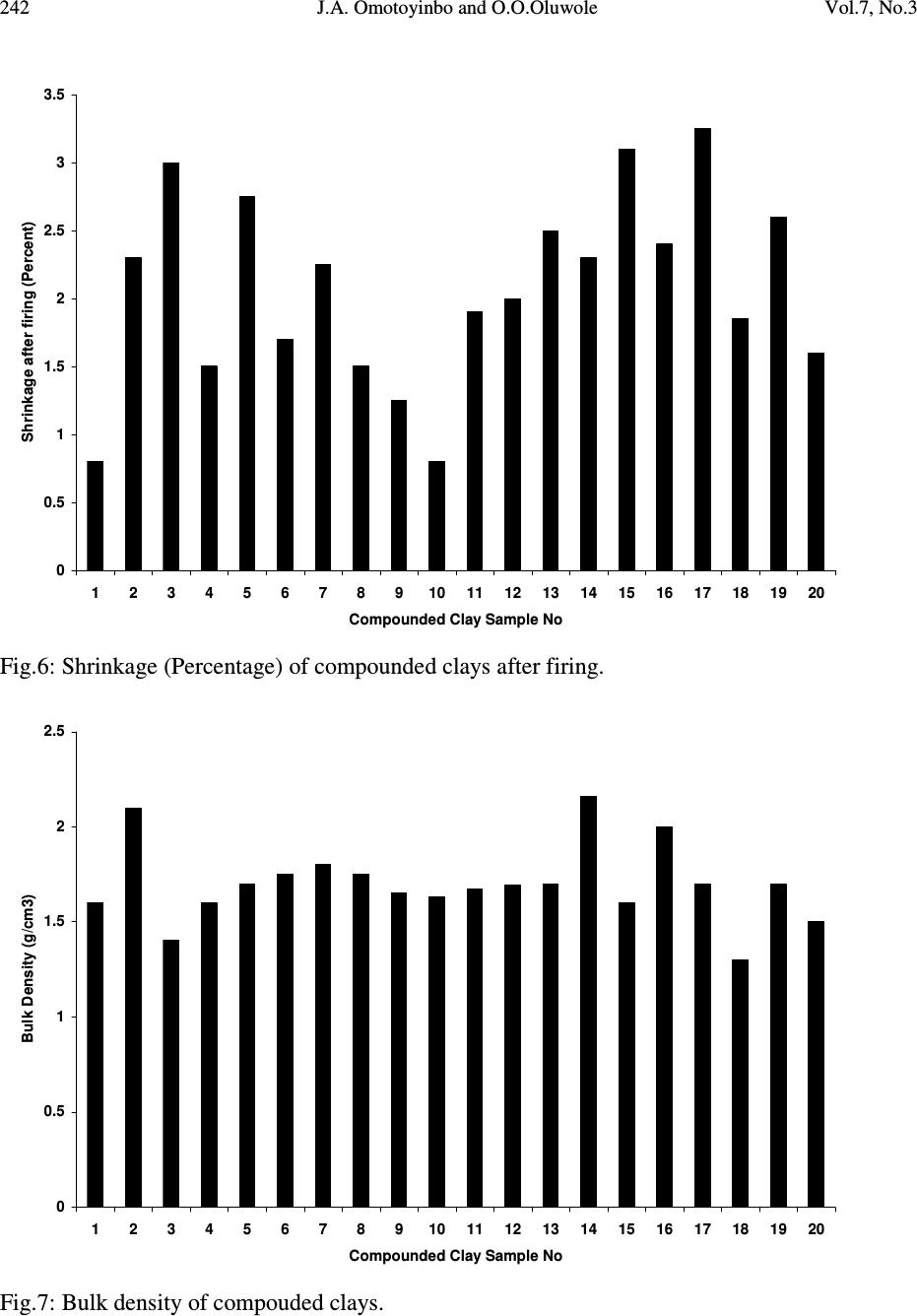 242 J.A. Omotoyinbo and O.O.Oluwole Vol.7, No.3 0 0.5 1 1.5 2 2.5 3 3.5 12345678910 11 12 131415 16 171819 20 Compounded Clay Sample No Shrinkage after firing (Percent) Fig.6: Shrinkage (Percentage) of compounded clays after firing. 0 0.5 1 1.5 2 2.5 12345678910 11 12 131415 16 171819 20 Compounded Clay Sample No Bulk Density (g/cm3) Fig.7: Bulk density of compouded clays. 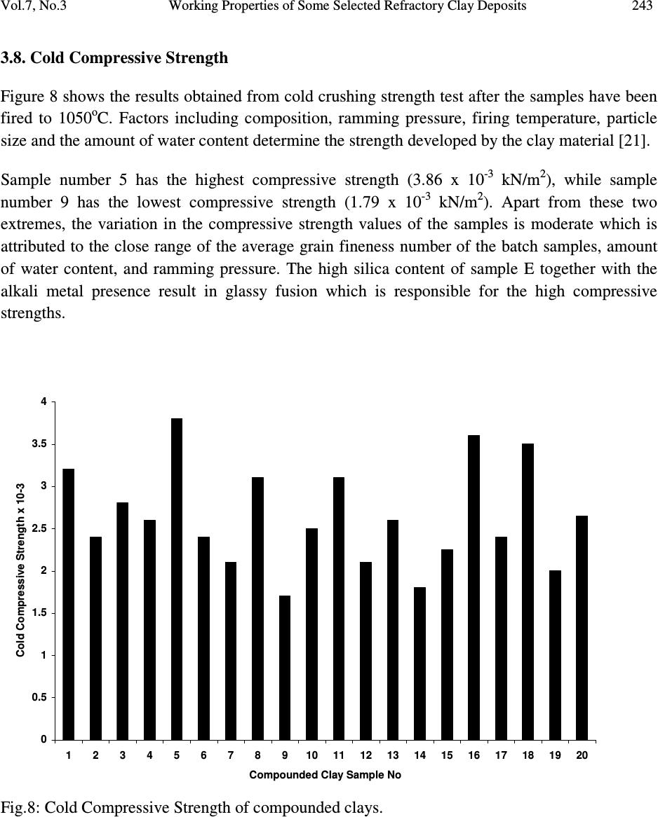 Vol.7, No.3 Working Properties of Some Selected Refractory Clay Deposits 243 3.8. Cold Compressive Strength Figure 8 shows the results obtained from cold crushing strength test after the samples have been fired to 1050 o C. Factors including composition, ramming pressure, firing temperature, particle size and the amount of water content determine the strength developed by the clay material [21]. Sample number 5 has the highest compressive strength (3.86 x 10 -3 kN/m 2 ), while sample number 9 has the lowest compressive strength (1.79 x 10 -3 kN/m 2 ). Apart from these two extremes, the variation in the compressive strength values of the samples is moderate which is attributed to the close range of the average grain fineness number of the batch samples, amount of water content, and ramming pressure. The high silica content of sample E together with the alkali metal presence result in glassy fusion which is responsible for the high compressive strengths. 0 0.5 1 1.5 2 2.5 3 3.5 4 12345678910 11 12 131415 16 171819 20 Compounded Clay Sample No Cold Compressive Strength x 10-3 Fig.8: Cold Compressive Strength of compounded clays.  244 J.A. Omotoyinbo and O.O.Oluwole Vol.7, No.3 4. CONCLUSION The result of the chemical analysis shows that the clay samples contain aluminum oxide (Al 2 O 3 ) and silica (SiO 2 ) as major constituents making them suitable as alumino-silicate refractory materials. The refractoriness of batch sample numbers 2 and 16 were the highest due to the relatively high content of aluminum oxide. The cold crushing strength and thermal shock resistance of the two samples are moderately high. The bulk density and apparent porosity of all the batch samples are high while the linear shrinkage values are low. Batch sample number 2 and 16 would be suitable for durance lining in non ferrous metal processing, but the high silica content which is highly susceptible to attack by ferrous oxide under reducing conditions will render them unsuitable for ferrous metal processing. The results of the investigation will be very useful and serve as a database for prospective investors and managers of metallurgical industries. REFERENCES 1. Ryan.W. (1978) “ Clay and Glazes for Potter” Pitman, London 2. Chesti. A.R (1986) “ Refractories: Manufacture, Properties and Applications Prentice –Hall, New Delhi. p.155 3. Balogun, S.A, Olubode, J.A and Aderibigbe, D.A (1980), “ Working properties of some Nigerian synthetic moulding sands” Nigerian Journal of Engineering and Technology, 3:39- 57 4. Balogun, S.A and Adepoju, O.T (1983) “ Effect of some additives on some moulding properties of a Nigerian moulding sand” Nigerian Journal of Engineering and Technology,5:61-68 5. Obikwelu, O.N. (1987), “Viability of local clays for the manufacture of refractories for steel and allied industries” Proceedings of the annual conference of the Nigerian Metallurgical Society 6. Hassan, S.B and Afewara, J.O.T (1994), “Refractory properties of some Nigerian clays” NSE Technical Transactions, 29(3), 13-19 7. Loto, C.A and Akeju, E.A (1994) “Durability of Igbokoda clay and silica sand as a synthetic moulding material” NSE Technical Transaction, 29(3), 21-27 8. Onyemaobi, O.O, Omotoyinbo, J.A and Borode, J.O (1995) “ Suitability of some local clays as refractory materials” Annual conference of the Science Association of Nigeria., University of Agriculture, Abeokuta, Nigeria.  Vol.7, No.3 Working Properties of Some Selected Refractory Clay Deposits 245 9. Ibitoye, S.A and Afonja, A.A (1997a) “ Adaptation of Ipetumodu potter’s clay to foundry use:1. Moulding properties of as mined and silica mixed potter’s clay.” Ife Journal of Technology,7(1):17-22 10. Ibitoye, S.A and Afonja, A.A (1997b) “ Adaptation of Ipetumodu potter’s clay to foundry use:2.Development of potter’s clay bound synthetic moulding sand.” Ife Journal of Technology, 7(1):39-45 11. Omotoyinbo, J.A, Onyemaobi, O.O and Borode, J.O (1997) “ Effects of potter’s clay additive on the moulding properties of Igbokoda silica sand” Global Journal of Pure and Applied Science, 3(3): 341-351 12. Jain, P.L (1979) “Principle of foundry technology. 2 nd Edition.McGrawHill, New Delhi p. 325 13. Rhodes, D (1979) “Clay and Glazes for potter” Pitman Publishers, London 14. Beely, P.R (1982) Foundry Technology, 3 rd Edition. Butterworth, London p.544 15. Dehlinger, G (2000) Science Vol.290 p.227 16. Green, M.A (2001) Nature Vol.412, p.805 17. Homewood, K. (2005) Materials Today, 8(1)p.34 18. Jastrzebski, D.Z. (1982) “The nature and properties of Engineering Materials” 2 nd Edition.pp.338-343 19. Hlavac, J. (1983) “The Technology of Glass and Ceramics, An Introduction” Elsevier Publishing, Amsterdam. Pp. 621 20. Chukwuogo, C.E.B. (1984) “ Physical and Chemical Properties of some Nigerian Clays” Research and Quality Control, DSC, Warri,Nigeria. 21. Grimshaw, R.W (1971) “ The Chemistry and Physics of Clays. 4 th edition Ernest Benn Publisheers, London. |