Paper Menu >>
Journal Menu >>
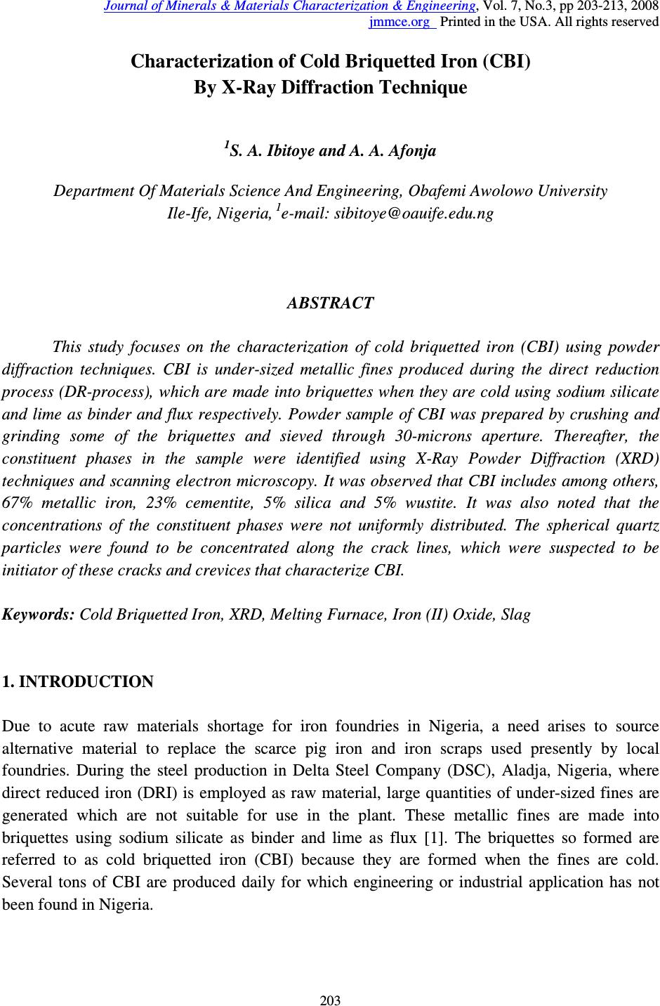 Journal of Minerals & Materials Characterization & Engineering, Vol. 7, No.3, pp 203-213, 2008 jmmce.org Printed in the USA. All rights reserved 203 Characterization of Cold Briquetted Iron (CBI) By X-Ray Diffraction Technique 1 S. A. Ibitoye and A. A. Afonja Department Of Materials Science And Engineering, Obafemi Awolowo University Ile-Ife, Nigeria, 1 e-mail: sibitoye@oauife.edu.ng ABSTRACT This study focuses on the characterization of cold briquetted iron (CBI) using powder diffraction techniques. CBI is under-sized metallic fines produced during the direct reduction process (DR-process), which are made into briquettes when they are cold using sodium silicate and lime as binder and flux respectively. Powder sample of CBI was prepared by crushing and grinding some of the briquettes and sieved through 30-microns aperture. Thereafter, the constituent phases in the sample were identified using X-Ray Powder Diffraction (XRD) techniques and scanning electron microscopy. It was observed that CBI includes among others, 67% metallic iron, 23% cementite, 5% silica and 5% wustite. It was also noted that the concentrations of the constituent phases were not uniformly distributed. The spherical quartz particles were found to be concentrated along the crack lines, which were suspected to be initiator of these cracks and crevices that characterize CBI. Keywords: Cold Briquetted Iron, XRD, Melting Furnace, Iron (II) Oxide, Slag 1. INTRODUCTION Due to acute raw materials shortage for iron foundries in Nigeria, a need arises to source alternative material to replace the scarce pig iron and iron scraps used presently by local foundries. During the steel production in Delta Steel Company (DSC), Aladja, Nigeria, where direct reduced iron (DRI) is employed as raw material, large quantities of under-sized fines are generated which are not suitable for use in the plant. These metallic fines are made into briquettes using sodium silicate as binder and lime as flux [1]. The briquettes so formed are referred to as cold briquetted iron (CBI) because they are formed when the fines are cold. Several tons of CBI are produced daily for which engineering or industrial application has not been found in Nigeria. 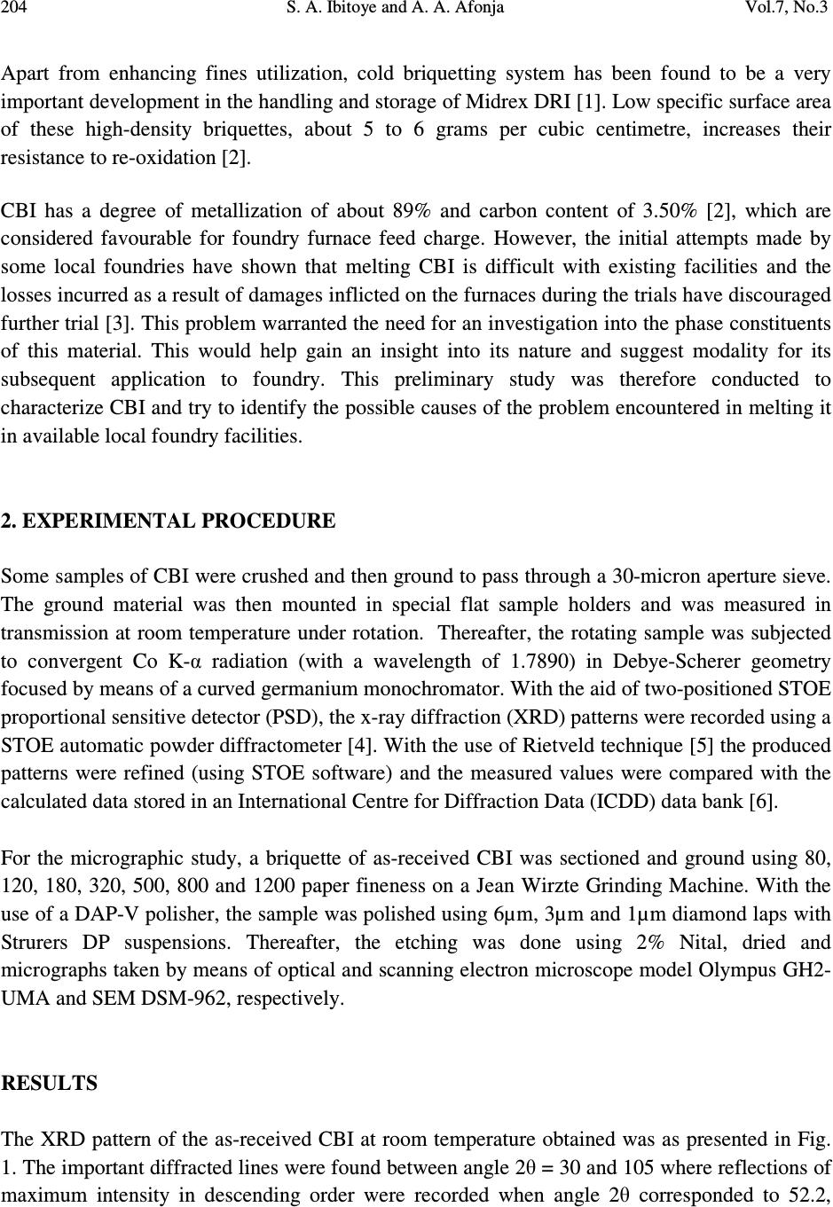 204 S. A. Ibitoye and A. A. Afonja Vol.7, No.3 Apart from enhancing fines utilization, cold briquetting system has been found to be a very important development in the handling and storage of Midrex DRI [1]. Low specific surface area of these high-density briquettes, about 5 to 6 grams per cubic centimetre, increases their resistance to re-oxidation [2]. CBI has a degree of metallization of about 89% and carbon content of 3.50% [2], which are considered favourable for foundry furnace feed charge. However, the initial attempts made by some local foundries have shown that melting CBI is difficult with existing facilities and the losses incurred as a result of damages inflicted on the furnaces during the trials have discouraged further trial [3]. This problem warranted the need for an investigation into the phase constituents of this material. This would help gain an insight into its nature and suggest modality for its subsequent application to foundry. This preliminary study was therefore conducted to characterize CBI and try to identify the possible causes of the problem encountered in melting it in available local foundry facilities. 2. EXPERIMENTAL PROCEDURE Some samples of CBI were crushed and then ground to pass through a 30-micron aperture sieve. The ground material was then mounted in special flat sample holders and was measured in transmission at room temperature under rotation. Thereafter, the rotating sample was subjected to convergent Co K-α radiation (with a wavelength of 1.7890) in Debye-Scherer geometry focused by means of a curved germanium monochromator. With the aid of two-positioned STOE proportional sensitive detector (PSD), the x-ray diffraction (XRD) patterns were recorded using a STOE automatic powder diffractometer [4]. With the use of Rietveld technique [5] the produced patterns were refined (using STOE software) and the measured values were compared with the calculated data stored in an International Centre for Diffraction Data (ICDD) data bank [6]. For the micrographic study, a briquette of as-received CBI was sectioned and ground using 80, 120, 180, 320, 500, 800 and 1200 paper fineness on a Jean Wirzte Grinding Machine. With the use of a DAP-V polisher, the sample was polished using 6µm, 3µm and 1µm diamond laps with Strurers DP suspensions. Thereafter, the etching was done using 2% Nital, dried and micrographs taken by means of optical and scanning electron microscope model Olympus GH2- UMA and SEM DSM-962, respectively. RESULTS The XRD pattern of the as-received CBI at room temperature obtained was as presented in Fig. 1. The important diffracted lines were found between angle 2θ = 30 and 105 where reflections of maximum intensity in descending order were recorded when angle 2θ corresponded to 52.2, 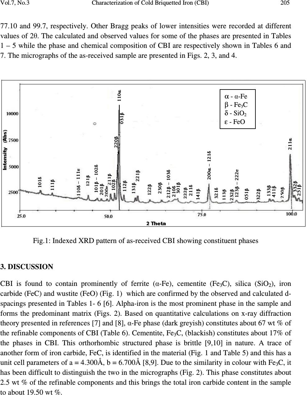 Vol.7, No.3 Characterization of Cold Briquetted Iron (CBI) 205 77.10 and 99.7, respectively. Other Bragg peaks of lower intensities were recorded at different values of 2θ. The calculated and observed values for some of the phases are presented in Tables 1 – 5 while the phase and chemical composition of CBI are respectively shown in Tables 6 and 7. The micrographs of the as-received sample are presented in Figs. 2, 3, and 4. Fig.1: Indexed XRD pattern of as-received CBI showing constituent phases 3. DISCUSSION CBI is found to contain prominently of ferrite (α-Fe), cementite (Fe 3 C), silica (SiO 2 ), iron carbide (FeC) and wustite (FeO) (Fig. 1) which are confirmed by the observed and calculated d- spacings presented in Tables 1- 6 [6]. Alpha-iron is the most prominent phase in the sample and forms the predominant matrix (Figs. 2). Based on quantitative calculations on x-ray diffraction theory presented in references [7] and [8], α-Fe phase (dark greyish) constitutes about 67 wt % of the refinable components of CBI (Table 6). Cementite, Fe 3 C, (blackish) constitutes about 17% of the phases in CBI. This orthorhombic structured phase is brittle [9,10] in nature. A trace of another form of iron carbide, FeC, is identified in the material (Fig. 1 and Table 5) and this has a unit cell parameters of a = 4.300Å, b = 6.700Å [8,9]. Due to the similarity in colour with Fe 3 C, it has been difficult to distinguish the two in the micrographs (Fig. 2). This phase constitutes about 2.5 wt % of the refinable components and this brings the total iron carbide content in the sample to about 19.50 wt %. α - α-Fe β - Fe 3 C δ - SiO 2 ε - FeO  206 S. A. Ibitoye and A. A. Afonja Vol.7, No.3 Table 1: The observed and calculated d-spacing and intensities of Alpha-Iron (α-Fe) at ambient temperature h k l d obs (Å) d cal (Å) I obs I cal 1 1 0 2.0405 2.0268 100 100 2 0 0 1.4322 1.4322 21 20 2 1 1 1.1694 1.1702 42 42 Table 2: The observed and calculated d-spacing and intensities of Cementite (Fe 3 C) at ambient temperature h k l d obs (Å) d cal (Å) I obs I cal 2 1 1 2.1010 2.1074 58 57 1 0 2 2.0680 2.0678 67 67 0 3 1 2.0100 2.0130 100 100 Table 3: The observed and calculated d-spacing and intensities of Quartz (SiO 3 ) at ambient temperature h k l d obs (Å) d cal (Å) I obs I cal 1 0 1 3.3472 3.3470 100 100 1 1 2 1.8165 1.8179 22 25 2 1 1 1.5404 1.5418 16 19 Quartz, SiO 2 , is found to be densely distributed along the cracks which look like grain boundaries (Fig. 3a). The SiO 2 particles seen are approximately spherical in shape and appear not to form any serious bond with one another or with neighbouring phases (Figs. 3b). These suggest that the observed cracks and most crevices in the sample originated from the SiO 2 particles that cannot form strong bonds with adjacent particles. A trace of wustite FeO is also found in the  Vol.7, No.3 Characterization of Cold Briquetted Iron (CBI) 207 sample (Fig. 1 and Table 4) which is calculated to be approximately 4.50 wt % of the refinable components in CBI. Table 4: The observed and calculated d-spacing and intensities of Wustite (FeO) at ambient temperature h k l d obs (Å) d cal (Å) I obs I cal 1 1 0 2.479 2.490 89 80 2 0 0 2.145 2.153 100 100 2 2 0 1.516 1.523 83 60 Table 5: The observed and calculated d-spacing and intensities of Cementite (FeC) at ambient temperature h k l d obs (Å) d cal (Å) I obs I cal 3 1 0 1.6013 1.2400 86 93 0 0 0 1.1243 1.1600 100 100 0 0 0 1.1034 1.1200 71 77 Table 6: The phase composition of cold briquetted iron Compound Composition [%] Alpha - Iron (α - Fe) 67.00 Cementite (Fe 3 C) 20.50 Quartz (SiO 3 ) 5.00 Cementite (FeC) 3.00 Wustite (FeO) 4.50  208 S. A. Ibitoye and A. A. Afonja Vol.7, No.3 Table 7: Chemical composition of Aladja CBI [2,12] Fig. 2: The micrograph of as-received CBI showing different phases. Component CBI (wt.%) Iron (Fe) 78.00 - 85.70 Iron (Fe, metallized) 81.60 - 89.00 Carbon (C) 3.50 – 4.03 Lime (CaO) 2.71 - 3.50 Aluminium oxide (Al 2 0 3 ) 0.70 – 0.72 Silica (SiO 2 ) 3.50 – 4.10 Phosphorous (P) 0.05 - 0.07 Sulphur (S) 0.004 - 0.005  Vol.7, No.3 Characterization of Cold Briquetted Iron (CBI) 209 (a) (b) Fig. 3: Microstructure of as-received CBI showing: (a) quartz pebbles concentrated mainly along the crack lines and (b) showing bond-free spherical quartz particles.  210 S. A. Ibitoye and A. A. Afonja Vol.7, No.3 The distribution of these phases in CBI varies from one point to the other. For instance, the chemical analysis of the section of the sample corresponding to Fig. 3a obtained from SEM among others, comprises of 67.92 % Fe, 16.53 % O 2 and 6.28% Si while a portion which corresponds to Fig. 3b among others, gives 57% C, 23.92% Fe, 14.41 % O 2 and 1.41 % Si. These deviate to some extent from the range of chemical composition of CBI (Table 7) earlier reported [2,12]. This is an indication of the non-homogeneous trait of CBI. In addition, it is characterized by pores, cavities and cracks of different sizes (Figs 3 and 4). These perhaps explain the porous nature of CBI. Fig. 4: Microstructure of as-received CBI showing the presence of cavities and pores of different sizes. Alpha-iron and carbides of iron do not pose any problem to the melting of CBI for α-Fe are easily melted while carbides of iron decomposed into carbon and metallic iron at temperature of about 738º C [13]. Quartz crystals on the other hand undergo structural transformations when heated. Ordinary or low quartz, when heated to 573° C is converted into high quartz, which has a different crystal structure and different physical properties. Between 870° C and 1470° C quartz exists in the form called tridymite, and above 1470° C, the stable form is known as cristobalite. This hexagonal structured phase melts at a high temperature of about 1710 ºC and often produces high volume of slag in iron making [14,15]. Though only about 5 wt.% of it is present in CBI, this magnitude is adequate to pose difficulty to melting of this material in conventional foundry melting furnaces. Wustite is unstable below 570 °C, which on slow cooling, decomposes into iron and magnetite [11]. This suggests that the wustite (FeO) is present in CBI in a metastable  Vol.7, No.3 Characterization of Cold Briquetted Iron (CBI) 211 state and this requires fluxes such as limestone in conventional iron making in order to reduce it into iron. As in conventional iron making in the blast furnace, limestone (CaCO 3 ) dissociates into calcium oxide and carbon dioxide (equation 1) when heated to a temperature of about 840 ºC to 1000ºC [14,15,16]. CaCO 3 = CaO + CO 2 ∆H = 178.57 KJ (1) Carbon dioxide formed is reduced to carbon monoxide by the available carbon in the solid fuel such as coke and other charged materials (equation 2) [14,15]. In this particular case, carbon can be picked up easily from major charged material itself, CBI, which consists of about 3.5 – 4.03 % carbon (Table 7). CO 2 + C = 2CO ∆H = -30.98 KJ (2) The carbon monoxide produced reduces FeO in CBI to metallic iron (equation 3). FeO + CO = Fe + CO 2 ∆H = - 17.32 KJ (3). The metallic iron so formed thereafter melts when the temperature of the furnace attains its melting point. The CaO and Al 2 O 3 in CBI (Table 7) and CaO formed from the decomposition of limestone (equation 1) combine with quartz to form slag [15]. The Al 2 O 3 is amphoteric oxide and so forms slag that is unlikely to pose much treat to furnace lining irrespective of whether is acidic or basic in nature. The CaO however, forms basic slag implying that it will react with furnace lining if it is acidic in nature [14,15]. The quantity of these oxides is substantial which also suggests formation of a voluminous slag. Melting FeO directly in foundry furnace therefore may pose a danger to melting furnaces if it is not designed to put its reduction into consideration. The difficulty encountered in melting CBI in the existing foundry facilities may therefore be attributed to the presence of high silica, possible reactions of some of the constituent oxides especially CaO with the furnace lining and unreduced iron (II) oxide contents (Table 6). Future facilities meant for melting CBI should therefore be designed to ensure adequate reduction of any unreduced iron oxide present. The type of linings selected for the furnace should ensure non-reaction with the formed slag. An effective dislagging mechanism must also be incorporated to intermittently remove the voluminous slag expected to be generated from the silica, the by-product from the reduced iron oxide and other available impurities during melting.  212 S. A. Ibitoye and A. A. Afonja Vol.7, No.3 CONCLUSION CBI consists essentially of alpha iron, cementite, silica and wustite. The silica present appears in a mixture with other constituent phases and it is suspected to be the main initiator of cracks that characterised CBI. CBI is not a homogeneous material; the quantity of constituent phases and elements vary from one point to the other. The difficulty experienced in melting CBI in existing foundry facilities is suspected to be attributed to the presence of fairly high quantity of unreduced iron (II) oxide and silica contents in the material. It is suggested that provision for the reduction of iron (II) oxide to iron and effective deslagging mechanism to take care of expected large volume of slag formed from the SiO 2 should be incorporated into a design of future foundry furnaces meant to melt CBI. ACKNOWLEDGEMENTS The Government of Germany is acknowledged for the DAAD fellowship awarded to conduct this research in Germany. Professor H. Fuess and Dr G. Miehe of Fachbereich Materialwiss, Fachgeb, Struckturforschung, Technical University of Damstadt, Germany are also acknowledged for making their laboratory and expertise readily available while carrying out this study. REFERENCE [1] Delta Steel Company Handbook, 1978, Technical Know-How Documentation, Warri, Voest-Alpine AG, Training Planning Department, Orientation Course 2, pp 82 115. [2] Delta Steel Company, 1984, Reinforcing Nigeria with Steel, DSC, Warri, p15. [3] Ibitoye, S. A., 2001, PhD Thesis, Obafemi Awolowo University, Ile-Ife. [4] Wölfel, E. R., 1983, J. Appl. Crystallogr., 16, pp 341-348. [5] Rietveld, H. M., 1969, J. Appl. Crytst. V2, pp 65 – 71. [6] Powder Diffraction File Card Nos. 6-696, 35-772, 33-1161, ICDD, Swarthmore, PA. [7] Averbach, K. P. and Cohen, C. M., 1948, X – Ray Diffraction Analyses, 3 rd ed.. Addison- Wesley, London, p 258. [8] Cullity, B. D., 1978, Element of X – Ray Diffraction, 2 nd ed., Addison-Wesley, London, p 407 – 417. [9] Vlack, V., 1980, Element of Materials Science and Engineering, 4 th ed., Addison-Wesley, Amsterdam, pp 1 - 148. [10] Higgins, A. H., 1991, Engineering Metallurgy – Part 1: Applied Physical Metallurgy, Kent, Hodder & Stoughton, pp 246 – 254. [11] Biswas, A. K., 1981, Principles of Blast Furnace Ironmaking, Australia, Cootha, pp 18 – 87.  Vol.7, No.3 Characterization of Cold Briquetted Iron (CBI) 213 [12] Omofoma, M. A. and Atanmo, P. N., 1986, Direct Reduction Process: Delta Steel Company, Nigeria Experience, Proceedings of the 4 th Annual Conference of Nigerian Metallurgical Society, Ajaokuta, p 58. [13] Gulyaev, A., 1980, Physical Metallurgy - Volume 1, Moscow, Mir, pp155-174, 198-246. [14] Linchevsky, V., Sobolevsky, A. and Kalmenev, A., 1980, Iron and Steel Making, Moscow, Mir, pp 58-60. [15] Titov, N.D., and Stepanov, Yu. A., 1981, Foundry Practice, Moscow, Mir, pp 284-286. [16] Cho, S., Joo, S., Cho, J., Yu, Y., Ahu, J., Han, C. and Kim, H., 2006, Kinetic Analysis of Decomposition of Calcium Carbonate using Danyang Limestone, Materials Science Forum, Vol 510 – 511, pp 502 – 505. |