Paper Menu >>
Journal Menu >>
 Journal of Minerals & Materials Characterization & Engineering, Vol. 7, No.2, pp 127-145, 2008 jmmce.org Printed in the USA. All rights reserved 127 Sigma Phase Formation and Embrittlement of Cast Iron-Chromium- Nickel (Fe-Cr-Ni) Alloys A. M. Babakr, A. Al-Ahmari, K. Al-Jumayiah, F. Habiby Saudi Basic Industries Corporation (SABIC) SABIC Technology Center-Jubail, P.O. Box 11669, Al-Jubail, 31961 Saudi Arabia ABSTRACT HK alloy is a member of the heat resistant cast alloy family (H-Series) steels. They are widely used in the petrochemical industry for components requiring enhanced high temperature properties. Microstructural changes occurring at high temperature clearly affects its mechanical properties. These properties have been shown in HK-40 steel subjected to high-temperature degradation and prone to the formation of sigma phase. The investigation carried out included metallurgical analysis, materials characterization and mechanical analysis. Metallurgical analysis included advanced metallography techniques to characterize its microstructure morphology and properties. Significant depletion of vital precipitates observed that definitely degraded its high temperature properties. Mechanical analysis included hardness profile, tensile testing of samples taken from the tree supports and tested in room temperature and in 800°C environments. Experimental results revealed that the structure of HK-40 affected by the formation of the high temperature brittle sigma-σ-phase. Nonetheless, mechanical properties did not suffer much at higher temperature. Keywords: Sigma-phase, Corrosion; Microstructure; Heat resistant steels; Hardness 1. INTRODUCTION Many components within oil, gas, thermal-power, chemical and petrochemical plants are casted of heat resistant alloys “HRA” to accommodate the operating high temperature environments. These alloys are experiencing variety of degrading mechanisms. As reliability sector of these plants are evolving, the assessment of damage and of the risk  128 A. M. Babakr, A. Al-Ahmari, K. Al-Jumayiah, F. Habiby Vol.7, No.2 associated with their degradation have become important and at times a priority. However, knowledge of potential mechanisms of degradation, rate at which damage may manifest and propagate with each component is a fundamental path in making proper assessment. The HRA drives its resistance because of the combinational effect of Fe-Ni- Cr “HP” or Fe-Cr-Ni “HK”. The majority of the reported deterioration in high temperature operating components are creep damage [1-5], microstructural degradation [6-8], high temperature fatigue [9-11], creep-fatigue [12-14], sigma-phase embrittlement [15-19] and carburization [20-22], hydrogen damage, graphitization, thermal shock, erosion, liquid metal embrittlement, and high temperature corrosion of various types. Generally, these failures are usually the results of microstructural changes at high temperature. Most of microstructural changes occur to alloys carbides constituents [23-24]. HRA such as HP and HK alloys original microstructure will consists of an austenite matrix with finer dispersions of carbides (Cr- rich M 23 C 6 or Nb-rich MC, depending on the alloy) in the matrix along with clusters of NbC and M 23 C 6 in the interdendritic regions and dispersions of M 23 C 6 along the seams between colonies of dendrites [25,26]. Microstructure will remain that way at room temperature and changes will only occur at elevated temperatures. For example, at 590 to 650°C (1100 to 1200°F), precipitation starts at regions near interdendritic and will grow with further exposure to same temperature. Carbon supply and depletion from the nearby regions is the controlling factor in further precipitation and growth of these carbides. As the component operating temperature increases beyond 650 to 970°C (1200-1778°F), carbides begin to coalescence as they grow causing decrease in amount of precipitation, and diminishing amount of remaining non-coalesced carbides. At much higher temperature, carbides become coarse and bulky. Theoretically, carbides coarsening at temperatures slightly below 1200°C (2192°F) reverses motion [15-26]. Precipitated carbides within the matrices begin to reverse back into solution. In reality, this can partially take place hindered by many operational parameters and type of alloy [27,28]. Experimentally, M 23 C 6 was predicted to be stable in HP6301 up to about 1250°C (2282°F) and to about 1282°C (2340°F) in HPCoW [28]. If the alloys were to remain in an operating temperature high enough to allow carbides (metal carbides) to grow and maintain its structure, then the material become sensitized. A counterpart to sensitization is sigma “σ” phase (metal-iron/metal-metal phase) formation, although different in composition but somewhat similar in location and precipitation mechanism.  Vol.7, No.2 Sigma Phase Formation And Embrittlement 129 The precipitation of σ-phase also is detrimental to the corrosion properties such as crevice and pitting corrosion resistance [29-30]. Formation temperature in open literature somewhat varies but with general agreement in the range of 620 to 900°C (1148-1652°F). The rate of formation and growth of σ- phase increases as temperature is held at 800°C (1472°F) [31,32] and had deleterious effect on the alloy’s mechanical properties. On the other hand, [33,34] reported that σ- phase will dissolve if held at 1000°C reverting into matrix, hence will not affect mechanical properties. This investigation has correlated formation and presence of σ-phase in heat resistant cast material HK-40 to its morphology and mechanical properties both at low and high temperature. 2. INVESTIGATION AND RESULTS HK-40 cast samples became available after industrial prolonged exposure to approximately 850°C (1562°F). The intended use of HK-40 was as structural support inside a furnace. The exposure duration was no more than 6 months or 4000 hours. While in actual practice, the alloy was subjected to regular operation and decoking regimes shutdowns when necessitates. Several samples suffered high temperature cracking, and all were of similar features. Figure 1 shows a fracture surface of one of the samples. Clearly, the fracture surface exhibits that of brittle failure with large facets. There was no apparent corrosion of any type and surface appeared oxidized. In addition, there was no plastic deformation or otherwise observed. The samples were sectioned and then prepared using standard metallographic techniques. The samples were electrolytically etched with a KOH and water solution was used to identify the carbides that were present in the microstructure. Microstructural characterization consisted of optical (OM) and scanning electron microscopes (SEM). Chemical compositions of the phases were determined without standards using an energy dispersive spectrometer (EDS) system that was attached to the SEM. Figure 2 shows an optical micrograph of a sample showing cross section of the fracture surface in the as etched condition showing dendritic microstructure typical of cast materials. Figure 3 is SEM photomicrograph showing a location just below the surface of the fracture. The whole surface has been oxidized. In the area of the same figure, sigma-σ- phase has been identified with aid of EDS. Figure 4 shows an image of an area within the sample along with its identified phases. Attacked phase was again σ-phase.  130 A. M. Babakr, A. Al-Ahmari, K. Al-Jumayiah, F. Habiby Vol.7, No.2 Figures 5, 6 and 7 show different locations within the sample where it has been attached and also contain σ-phases and secondary carbides precipitates. Cracks were filled with Figure 1. Fracture surface of one of the samples-HK-40. Figure 2. Cross section of the HK-40 sample, etched, KOH. Figure 3. SEM optical micrographs showing cross section sample in the as polished condition along with its EDS analysis. Elemental analysis indicates oxide formation. 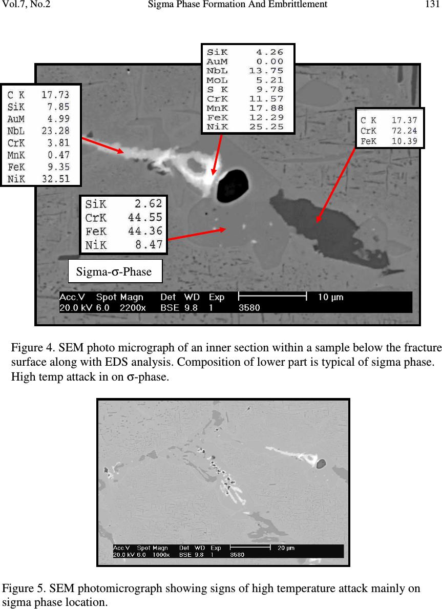 Vol.7, No.2 Sigma Phase Formation And Embrittlement 131 Figure 4. SEM photo micrograph of an inner section within a sample below the fracture surface along with EDS analysis. Composition of lower part is typical of sigma phase. High temp attack in on σ-phase. Figure 5. SEM photomicrograph showing signs of high temperature attack mainly on sigma phase location. Sigma- σ -Phase 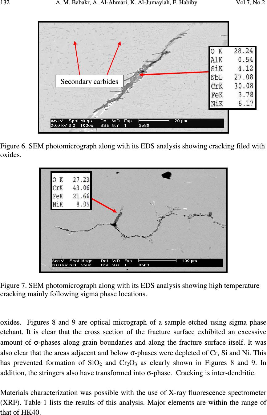 132 A. M. Babakr, A. Al-Ahmari, K. Al-Jumayiah, F. Habiby Vol.7, No.2 Figure 6. SEM photomicrograph along with its EDS analysis showing cracking filed with oxides. Figure 7. SEM photomicrograph along with its EDS analysis showing high temperature cracking mainly following sigma phase locations. oxides. Figures 8 and 9 are optical micrograph of a sample etched using sigma phase etchant. It is clear that the cross section of the fracture surface exhibited an excessive amount of σ-phases along grain boundaries and along the fracture surface itself. It was also clear that the areas adjacent and below σ-phases were depleted of Cr, Si and Ni. This has prevented formation of SiO 2 and Cr 2 O 3 as clearly shown in Figures 8 and 9. In addition, the stringers also have transformed into σ-phase. Cracking is inter-dendritic. Materials characterization was possible with the use of X-ray fluorescence spectrometer (XRF). Table 1 lists the results of this analysis. Major elements are within the range of that of HK40. Secondary carbides 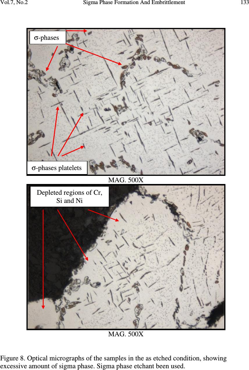 Vol.7, No.2 Sigma Phase Formation And Embrittlement 133 MAG. 500X MAG. 500X Figure 8. Optical micrographs of the samples in the as etched condition, showing excessive amount of sigma phase. Sigma phase etchant been used. σ -phases platelets σ -phases Depleted regions of Cr, Si and Ni  134 A. M. Babakr, A. Al-Ahmari, K. Al-Jumayiah, F. Habiby Vol.7, No.2 MAG. 1000X MAG. 1000x Figure 9. Optical micrographs of the samples in the as etched condition showing sigma phases and secondary carbides precipitates. σ -phases σ -phases platelets Secondary carbides 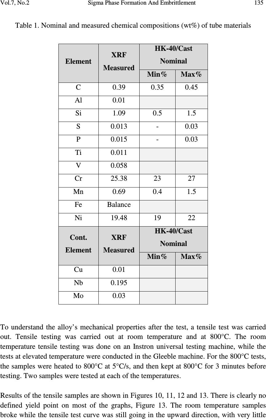 Vol.7, No.2 Sigma Phase Formation And Embrittlement 135 Table 1. Nominal and measured chemical compositions (wt%) of tube materials Element XRF Measured HK-40/Cast Nominal Min% Max% C 0.39 0.35 0.45 Al 0.01 Si 1.09 0.5 1.5 S 0.013 - 0.03 P 0.015 - 0.03 Ti 0.011 V 0.058 Cr 25.38 23 27 Mn 0.69 0.4 1.5 Fe Balance Ni 19.48 19 22 Cont. Element XRF Measured HK-40/Cast Nominal Min% Max% Cu 0.01 Nb 0.195 Mo 0.03 To understand the alloy’s mechanical properties after the test, a tensile test was carried out. Tensile testing was carried out at room temperature and at 800°C. The room temperature tensile testing was done on an Instron universal testing machine, while the tests at elevated temperature were conducted in the Gleeble machine. For the 800°C tests, the samples were heated to 800°C at 5°C/s, and then kept at 800°C for 3 minutes before testing. Two samples were tested at each of the temperatures. Results of the tensile samples are shown in Figures 10, 11, 12 and 13. There is clearly no defined yield point on most of the graphs, Figure 13. The room temperature samples broke while the tensile test curve was still going in the upward direction, with very little 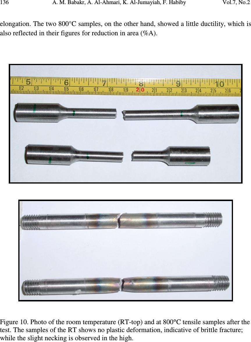 136 A. M. Babakr, A. Al-Ahmari, K. Al-Jumayiah, F. Habiby Vol.7, No.2 elongation. The two 800°C samples, on the other hand, showed a little ductility, which is also reflected in their figures for reduction in area (%A). Figure 10. Photo of the room temperature (RT-top) and at 800°C tensile samples after the test. The samples of the RT shows no plastic deformation, indicative of brittle fracture; while the slight necking is observed in the high. 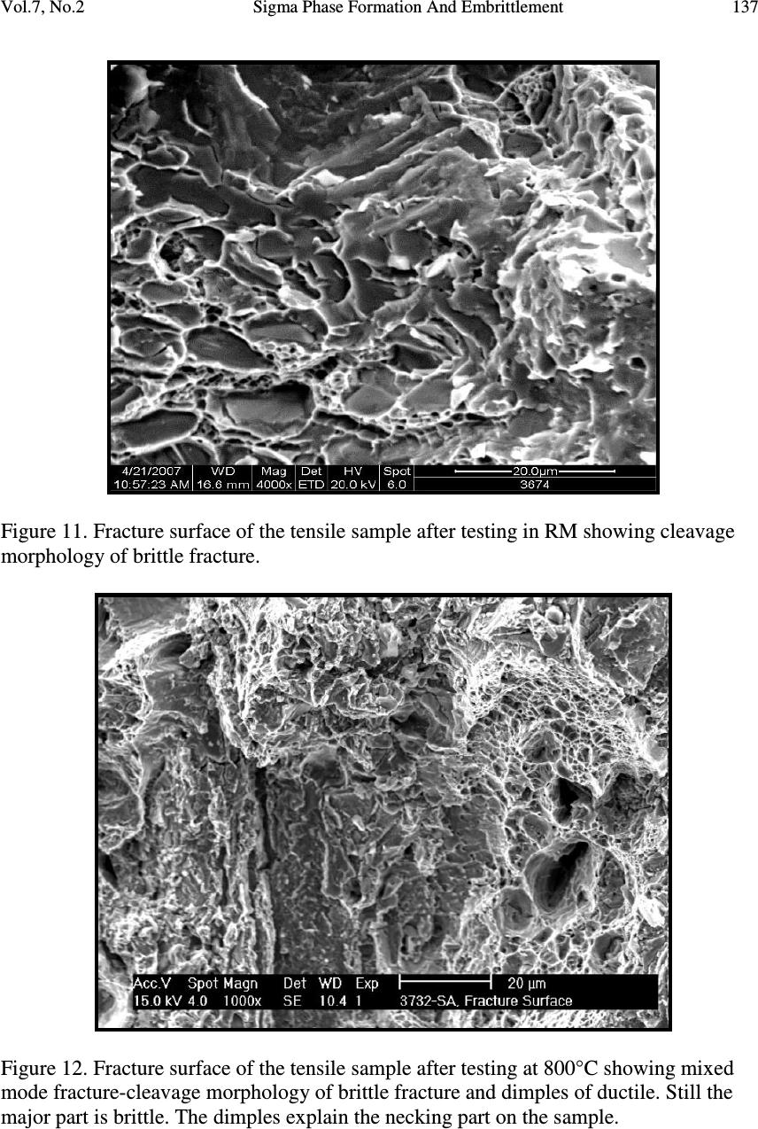 Vol.7, No.2 Sigma Phase Formation And Embrittlement 137 Figure 11. Fracture surface of the tensile sample after testing in RM showing cleavage morphology of brittle fracture. Figure 12. Fracture surface of the tensile sample after testing at 800°C showing mixed mode fracture-cleavage morphology of brittle fracture and dimples of ductile. Still the major part is brittle. The dimples explain the necking part on the sample. 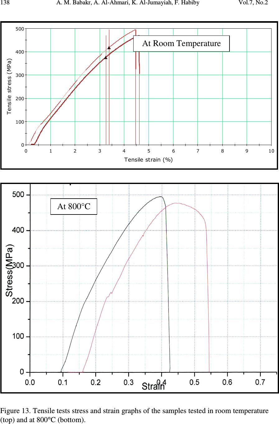 138 A. M. Babakr, A. Al-Ahmari, K. Al-Jumayiah, F. Habiby Vol.7, No.2 0 100 200 300 400 500 0 12 34 5 67 8910 Tensile stress (MPa) Tensile strain (%) Figure 13. Tensile tests stress and strain graphs of the samples tested in room temperature (top) and at 800°C (bottom). At 800°C At Room Temperature 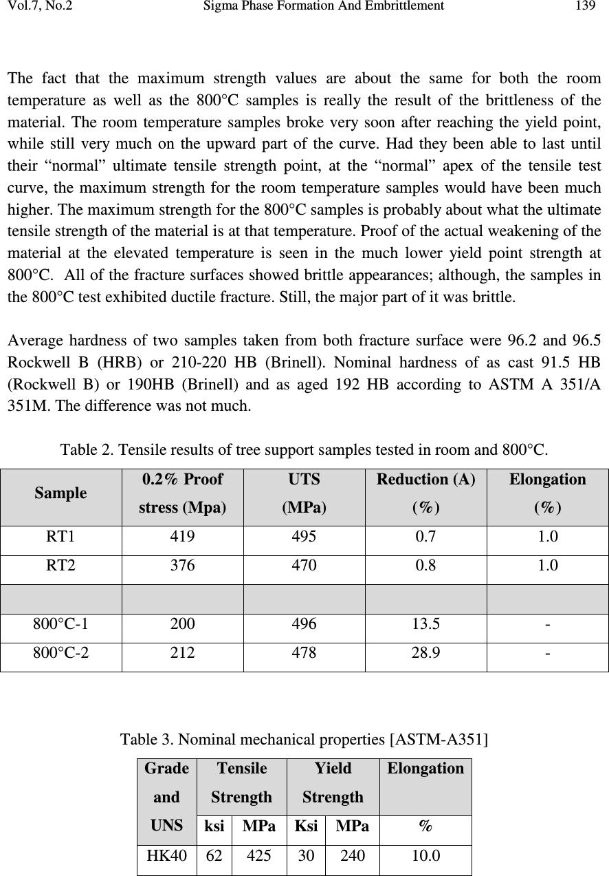 Vol.7, No.2 Sigma Phase Formation And Embrittlement 139 The fact that the maximum strength values are about the same for both the room temperature as well as the 800°C samples is really the result of the brittleness of the material. The room temperature samples broke very soon after reaching the yield point, while still very much on the upward part of the curve. Had they been able to last until their “normal” ultimate tensile strength point, at the “normal” apex of the tensile test curve, the maximum strength for the room temperature samples would have been much higher. The maximum strength for the 800°C samples is probably about what the ultimate tensile strength of the material is at that temperature. Proof of the actual weakening of the material at the elevated temperature is seen in the much lower yield point strength at 800°C. All of the fracture surfaces showed brittle appearances; although, the samples in the 800°C test exhibited ductile fracture. Still, the major part of it was brittle. Average hardness of two samples taken from both fracture surface were 96.2 and 96.5 Rockwell B (HRB) or 210-220 HB (Brinell). Nominal hardness of as cast 91.5 HB (Rockwell B) or 190HB (Brinell) and as aged 192 HB according to ASTM A 351/A 351M. The difference was not much. Table 2. Tensile results of tree support samples tested in room and 800°C. Sample 0.2% Proof stress (Mpa) UTS (MPa) Reduction (A) (%) Elongation (%) RT1 419 495 0.7 1.0 RT2 376 470 0.8 1.0 800°C-1 200 496 13.5 - 800°C-2 212 478 28.9 - Table 3. Nominal mechanical properties [ASTM-A351] Grade and UNS Tensile Strength Yield Strength Elongation ksi MPa Ksi MPa % HK40 62 425 30 240 10.0  140 A. M. Babakr, A. Al-Ahmari, K. Al-Jumayiah, F. Habiby Vol.7, No.2 3. DISCUSSION Sigma (σ) phase (iron-chromium compound) can develop in austenitic stainless steels as seen in the Figures 4 to 9. It is hard-brittle intermetallic phase. For this reason it has a direct effect on the mechanical property of the metal. It can form when service temperature is within 565-952°C (1050-1700°F). The upper limit for sigma phase formation varies from 870 to 980°C (1600 to 1800°F) [35, 28]. For example, embrittlement in 304SS usually occurs slowly. Only about 2 to 3% sigma phase will show in its macrostructure after 10 years at 650°C (1200°F) [36]. Near 900 °C, it forms within a couple of minutes [37, 38]. The testing temperature is well within the upper limits, as actually occurring in real case situation, embrittlement can occur in a much faster mode. Although sigma phase has been detected and its effect on the material embrittlement has been established, it is not the sole cause of the failure. It was more of an assistant. Sigma (σ) phase is hard and fragile and its formation causes loss of toughness. In addition, when formed, it consumes chromium and molybdenum present within the matrix, which leads to the depletion in these elements as has been seen in the Figures. On the other hand, it is usually not detrimental at high temperature, but if cooled below 260°C (50°F) or below, it will result in almost complete loss of toughness [39]. The problem becomes serious when the phase is continuous in some parts of the material, as in our case. Intergranular corrosion will result in selective attack of this phase Iron-base alloys with high chromium contents 18 to 25 wt% are generally prone to brittle sigma-phase formation during prolonged exposures above 650°C. Qualitatively, alloys with nickel contents greater than 30 wt% are less prone to sigma-formation but are more susceptible to corrosion in high temperature environments. The precipitation of Fe-Cr sigma phase, which occurs predominantly at grain boundaries in the alloy, can lead to considerable reduction in creep ductility at elevated temperatures and loss of fracture toughness when the components are cooled to room temperature. The allowable stress data presented earlier are based on extrapolated values from short-time test data and do not account for the property reduction due to microstructural changes in the alloy [40]. In this investigation, typical sigma phase composition was 45% Fe, 44% Cr, 9% Ni and 3% Si complementing other investigators findings [10, 41]. As normally produced, the HK alloy type is stable austenitic over its entire temperature range of application. The as-cast microstructure consists of an austenite matrix containing massive carbides as scattered islands or networks. After aging at service temperature, the alloy exhibits a dispersion of fine, granular carbides within the austenite grains, with  Vol.7, No.2 Sigma Phase Formation And Embrittlement 141 subsequent agglomeration if the temperature is high enough. These fine, dispersed carbides contribute to the creep strength of the alloy. The most susceptible site for the formation of sigma phase is the grain boundaries for its high-energy [42]. In other words, the smaller the size of the area the greater tendency of the formation. Hence, formation of this phase was possible in this cast material due to its dendritic microstructure and smaller sizes. Induced dislocations contribute directly to the alloy’s strength and resistance. Interaction of carbide’s growth and dislocations are of special interest. Once carbides grow past certain size, their interaction with dislocations becomes less effective and, consequently, the alloys start losing their strength. Carbide precipitates grow not only by diffusion processes, but also by coalescence with one another to reclaim size. The higher the temperature, the farther their growth and coalescence progression become. A lamellar (stringers) constituent tentatively identified as an austenite, carbonitride eutectoid resembling pearlite also is frequently observed in HK alloys but its exact nature is in doubt [40]. If these phases are present in excessive amounts, it will not affect the alloy strength at high temperature. Only affecting factor in the failure is the unbalanced composition of these phases. This is always possible within the previously mentioned nominal chemical ranges of this grade, and in this event, some ferrite is present in the austenite matrix, which will directly affect the local metallurgical and mechanical properties. This ferrite that is adjacent to the austenite will transform to the brittle sigma phase if the alloy is held for more than short times around 816°C (1500°F) with consequent weakening at this temperature and embrittlement [43]. The direct implication of sigma phase precipitation and growth will cause Cr and Si depletion, in the surrounding metallic matrix next to it (Figure 8), and will further reduces HK-40 metal dusting resistance as been reported elsewhere [44]. Formation of sigma phase in HK type alloy can occur directly from austenite in the range 760 to 871°C (1400 to 1600°F) particularly at the lower carbon level (0.20-0.30 percent), and for this reason a substantial break up in properties at halfway temperatures is observed for this grade [45]. Comparing other alloys, for instance, other alloys with higher nickel, in the same environment would be beneficial. The higher the nickel the more stable the austenitic structure, which imparts high temperature corrosion resistance. In addition, nitrogen stabilizes austenite, which results in the control of sigma formation [46], and at time resistance [47-49]. 4. CONCLUSIONS In this study, microstructural and mechanical properties changes in HK-40 subjected to sigma-phase formation were characterized. As sigma-phase, at 850°C, precipitation and  142 A. M. Babakr, A. Al-Ahmari, K. Al-Jumayiah, F. Habiby Vol.7, No.2 growth advances, Cr and Si depletion, in the surrounding matrix next to it occur. This resulted in a reduction in HK-40 sigma phase and high temperature properties resistance. Silica was found in all parts of sigma phases analyzed. The hardness did not show very much effect because of sigma phase, the increase was trivial. Sigma phase exhibited a stable spheroid shape. In addition, the larger needle-like particles within the grains were metallographically identified as sigma phase. REFERENCES 1. ASM handbook, failure analysis and prevention, vol. 11, ASM International, Materials Park (OH) (1996). 2. Colangelo, V.J. and Heiser, F.A., Analysis of metallurgical failures (2nd ed.), Wiley, New York (NY) (1987). 3. El-Batahgy, A. and Zaghloul, B., “Creep failure of cracking heater at a petrochemical plant,” Materials Characterization, v. 54, n. 3, March 2005, 239- 245 4. Kumar, R.A., Sinha, S.K., Tiwari, Y.N., Swaminathan, J., Das, G. and Chaudhuri S., Analysis of failed reformer tubes, Engineering Failure Analysis, 10 (2003), 351-358. 5. Ashby, M.F. Deformation-Mechanism, Maps, Acta Metallurgica, v. 20, 887-897, 1972. 6. Dyson, B. Use of CDM in Materials Modeling and Component Creep Life Prediction, J. Pressure Vessel Technol., v. 122, 281-296, 2000. 7. Ejaz, N. and Tauqir, A., “Failure due to structural degradation in turbine blades,” Engineering Failure Analysis, v.13, n. 3, April 2006, 452-463. 8. Barbosa, C., Nascimento, J.L., Caminha, I.M.V. and. Abud, I.C, “ Microstructural aspects of the failure analysis of nickel base superalloys components, “Engineering Failure Analysis, v. 12, n. 3, June 2005, 348-361 9. Pang, H.T., and Reed, P.A.S.k, “Microstructure effects on high temperature fatigue crack initiation and short crack growth in turbine disc nickel-base superalloy Udimet 720Li,” Materials Science and Engineering: A, v. 448, n. 1-2, 15 March 2007, 67-79. 10. Coreño-Alonso, O., Duffus-Scott, A., Zánchez-Cornejo, C., Coreño-Alonso, J., de Jesús, F.S., and Bolarín-Miró, A., “On the effect of σ-phase formation during metal dusting,” Materials Chemistry and Physics, v. 84, n. 1, March 2004, 20-28. 11. Kobayashi, K., Yamaguchi, K., Hayakawa, M., and Kimura, M., “Grain size effect on high-temperature fatigue properties of alloy718,” Materials Letters v.59, n. 2-3, February 2005, 383-386. 12. Bulloch, J. H. and Bernard, P. J.,” A remaining life assessment of a cracked attemperator steam line,” Engineering Failure Analysis, v.8, n. 6, December 2001, 529-540.  Vol.7, No.2 Sigma Phase Formation And Embrittlement 143 13. Shang, D.G., Sun, G.Q., Yan,C.L., Chen, J.H., and Cai, N., “Creep-fatigue life prediction under fully-reversed multiaxial loading at high temperatures,” International Journal of Fatigue, v. 29, n. 4, April 2007, 705-712. 14. Inoue, T., Okazaki, M., Igari, T., Sakane, M. and Kishi, S., “Evaluation of fatigue-creep life prediction methods in multiaxial stress state,” Nuclear Engineering and Design 126 (1991), 13–21. 15. Ogata, T. and Yaguchi, M., “Damage mechanism in weldment of 2.25Cr–1Mo steel under creep–fatigue loading,” Engineering Fracture Mechanics v. 74, n. 6, April 2007, 947-955. 16. Elmer, J.W., Palmer , T.A., and Specht, E.D., “In situ observations of sigma phase dissolution in 2205 duplex stainless steel using synchrotron X-ray diffraction,” Materials Science and Engineering: A 459 (2007) 151–155. 17. Kington, A. V. and Noble, F. W., “σ phase embrittlement of a type 310 stainless steel,” Materials Science and Engineering A, Volume 138, Issue 2, 15 June 1991, 259-266. 18. Barcik, J, “The kinetics of σ-phase precipitation in AISI310 and AISI316 steels,” Metallurgical and Materials Transactions: A, v. 14, n. 3, March, 1983, 635-641. 19. Solomon, H.D., Devine, T.M., in R.D. Lula (Ed.), Duplex Stainless Steels, American Society for Metals, Metals Park, OH, 1983, pp. 693–756. 20. Sedriks,J., “Corrosion of Stainless Steels”, John Wiley & Sons, 2nd edition (New York, NY 1996), p. 22. 21. Jahromi, S.A.J., Javadpour, S., and Gheisari, Kh., “Failure analysis of welded joints in a power plant exhaust flue,” Engineering Failure Analysis, v. 13, n. 4, June 2006, 527-536. 22. Honeycombe, R.W.K. Steels: Microstructure and Properties, (Arnold, London, 1995-2 nd ed). 23. Brett, S.J., “In-service cracking mechanism affecting 2CrMo welds in 1/2CrMoV steam pipework systems,” Proceeding of international conference on integrity of high-temperature welds, IOM (1998), pp. 3–14. 24. Peckner, D., Bernstein, I. M., Handbook of Stainless Steels, McGraw-Hill, 1977. 25. Lamb, S. and Bringas, J.E., eds, Practical Handbook of Stainless Steels & Nickel Alloys ASM International; 1 edition (October 1999). 26. Blair, M. C., “Cast Stainless Steels,” Metals Handbook, Vol. 1 (Materials Park, OH: ASM International, 1990), 908. 27. Zhu, S. J., Wang, Y. and Wang, F. G., ”Comparison of the creep crack growth resistance of HK40 and HP40 heat-resistant steels, Journal of Materials Science Letters, v. 9, n. 5, May, 1990, 520-521. 28. Pankiw, R. I., Voke, D.P., Muralidharan, G., Evans, N. D., Stevens, C. O., Liu, K. C., Santella, M. L., Maziasz, P. J., and Sikka, V. K,. “Precipitation and its effect on the design of cast heat resistant alloys,” Corrosion/ 2007, paper 7424.  144 A. M. Babakr, A. Al-Ahmari, K. Al-Jumayiah, F. Habiby Vol.7, No.2 29. Authors’ personal investigative experiences. 30. Ezuber, H.M., El-Houd, A., El-Shawesh, F., “Effects of sigma phase precipitation on seawater pitting of duplex stainless steel,” Desalination 207, 2007, 268–275. 31. Lopez, N., Cid, N., and Puiggali, M., “Influence of σ-phase on mechanical properties and corrosion resistance of duplex stainless steels, “Corrosion Science, v. 41, n. 8, 1 August 1999, 1615-1631. Scripta Materialia, v. 50, n. 10, May 2004, 1351-1354. 32. Johnson, E., Kim, Y.J., Chumbley, L.S., and Gleeson, B., “Initial phase transformation diagram determination for the CD3MN cast duplex stainless steel,” 33. Wilms, M.E., Gadgil, V.J., Krougman, J.M., Kolster, B.H., “Effect of σ-phase precipitation at 800°C on the mechanical properties of a high alloyed duplex stainless steel,” Materials at High Temperatures, v. 9, n. 3, August 1991, 160-166. 34. Patankar, S.N., Tan, M.J., “Sigma phase precipitation during superplastic forming of duplex stainless steel,” Materials at High Temperatures, v. 19, n. 1, 2002, 41- 44. 35. M. C. Blair, “Cast Stainless Steels,” Metals Handbook, ASM International, V.1 1990), page, 908. 36. Hansen, D. A., and Puyear, R.B., Materials selection for hydrocarbon and chemical plants, Marcel Dekker, INC., 1996. 37. Hau, J., and Seijas, A., “Sigma phase embrittlement of stainless steel in FCC service,” CORROSION2006, paper 06578. 38. Metals Handbook, Vol. 13: Corrosion, ASM International, Metals Park, Ohio, 1987, p. 11. 39. Li, J., Wu, T., and Riquier, Y., “Sigma phase precipitation and its effect on the mechanical properties of a super duplex stainless steel, “Materials Science. And Engineering, A174, p. 149-156 (1994). 40. Tiong, D.K-K, Walsh, J., and, McHaney, J.H.,”Technical challenges in using super duplex stainless steel,” CORROSION2006, paper6147. 41. Vander Voort, G.F., Properties and selection: iron steels and high performance alloys, Metals Handbook, vol. 1, 10th ed., ASM International, 2001, p. 709. 42. Kobayashi, D.Y., and Wolynec, S., “Evaluation of the low corrosion resistant phase formed during the sigma phase precipitation in duplex-stainless steels,” Materials Research, 1999, vol. 2, no. 4, pp. 239-247. 43. Natesan, K., “Materials performance in coal fluidized bed combustion environment,” 10 th International Pittsburgh Coal Conference, Pittsburgh, PA, September 20--24, 1993. 44. Sedriks, A.J. Corrosion of Stainless Steels, 2nd edition, John Wiley & Sons, 1996. 45. Zucato, I., Moreira, M.C., Machado, I.F., and Lebrao, S.M., “ Microstructural characterization and the effect of phase transformations on toughness of the UNS  Vol.7, No.2 Sigma Phase Formation And Embrittlement 145 S31803 duplex stainless steel aged treated at 850°C,” Materials Research, July/Sept. 2002, vol.5, no.3, p.385-389. 46. STEEL CASTINGS HANDBOOK Supplement 9 High Alloy Data Sheets Heat Series Steel Founders' Society of America 2004 47. Dove, D., Messer, B., and Phillips, T.,”An austenitic stainless steel, resistant to high temperature creep and naphthenic acids attack in refinery environments,” CORROSION2001, paper 01523. 48. Nicolio, C.J., and Holmquist, M., “Duplex alloys; challenging corrosion in the New millennium,” CORROION2002, paper 02120. 49. Tang, Y.J., Wang, Q.M., Yuan, F.H., Gong, J., and Sun, C., “High-temperature oxidation behavior of arc ion plated NiCoCrAlYSiB coatings on cobalt-based super alloy,” Journal of Materials Research, Vol. 21, No. 3, page 737. Mar 2006. |

