Paper Menu >>
Journal Menu >>
 Journal of Minerals & Materials Characterization & Engineering, Vol. 5, No.1, pp 63-72, 2006 jmmce.org Printed in the USA. All rights reserved 63 Nanoindentation Study on Tourmaline M.O. Adeoye1 and O.O. Adewoye2 1Department of Materials Science and Engineering, Obafemi Awolowo University, Ile-Ife. Nigeria. madeoye@oa u ife.edu.ng 2National Agency for Science & Engineering Infrastructure, Abuja. Nigeria. Abstract Nanoindentation tests were performed on the basal (0001) and prismatic (10ī0) surfaces of tourmaline crystals. These results were used along with Vickers microhardness tests to investigate the hardness of the material on these surfaces at different load regimes. It was found that the (0001) surface indicated a higher hardness at ultra-low loads while (10ī0) becomes the harder plane at higher loads. Evidence of plastic deformation at room temperature in the otherwise very brittle (ceramic) material was also established, and the elastic modulus was determined. Keywords: Tourmaline; Minerals; Mechanical properties; Hardness testing; Nanoindentation INTRODUCTION An ultra-low-load indentation test or nanoindentation technique is now a prevailing method for near-surface studies [1-7]. This technique has become particularly useful in the study of mechanical properties and behaviour of thin films and coated systems [8-10]. The nanoindentation technique has been established as a means of determining the behaviour of small volumes of materials and materials with very fine microstructures, and is especially useful for studying nanophase composites. This method is also useful in probing the mechanisms controlling very near-surface mechanical properties of materials. The problems associated with the post facto measurements of indentations in microhardness tests are removed in this method by producing continuous load-depth-stiffness-time data [4,5]. With accurate calibration of the tip-end geometry, a continuous measurement of the indenter- specimen contact can yield the elastic modulus value for the small sample volume being investigated [4]. The instrument used in this work, the Nano Indenter™ II, is fitted with a Berkovich tip (a regular triangular pyramid tip) reliably calibrated for loads down to 100 mN. And it is used to obtain, in particular, the elastic modulus and the hardness of the material investigated. Calibration of the indenter shape is very critical to the determination of the elastic properties and the hardness. This is more so since the indenter tip is more blunt than an ideal pyramid, hence the use of an ideal geometry for the indenter will result in a large overestimate of the hardness, especially at small depths [1]. A typical load-displacement curve obtained for an elastic-plastic material using the nanoindenter is shown in Figure 1. The total depth, hmax, is the depth of the indenter at peak load, Pmax. The plastic depth, hc, is the depth of the indenter in contact with the sample under load. The final depth, hf, is the depth of indentation after unloading and it shows a significant 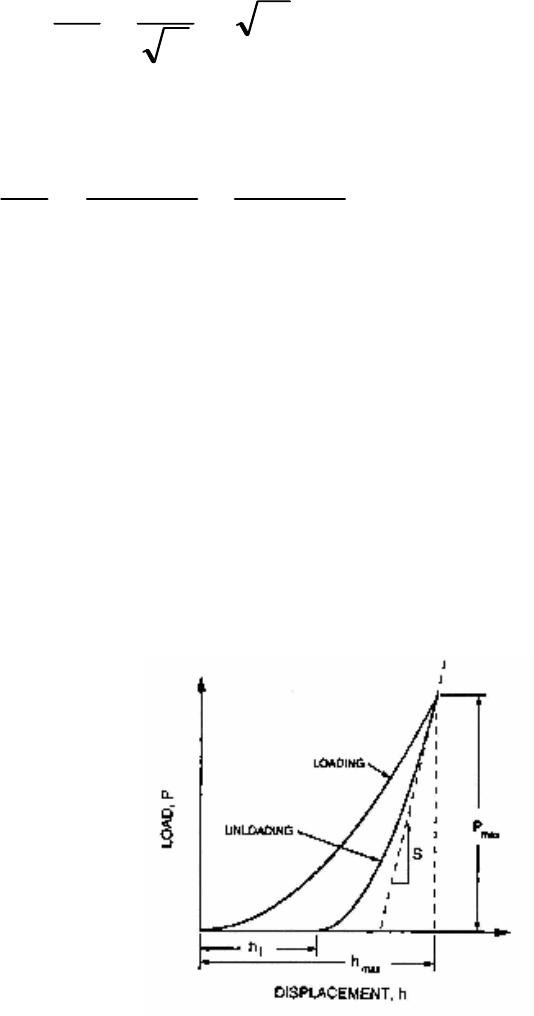 64 M.O. Adeoye and O. O. Adewoye Vo1.5, No.1 decrease due to elastic recovery. The shape of the unloading curve can be used as a means of obtaining the elastic properties of the sample [1]. The slope, S, is the initial unloading stiffness and is given by [2,11] (1) AE π 2 dh dP Sr == where A is the projected area of contact and is determined by a method that has been developed and described by Oliver and Pharr [2]. Er is the composite modulus given by (2) E )v-(1 E )v-(1 E 1 i 2 i s 2 s r += Es and vs are the elastic modulus and Poisson's ratio for the sample and, Ei and vi are the same parameters for the indenter. Using this technique the elastic modulus and the hardness of a material can be measured to within ±10% or better [11]. The hardness, H, defined as the mean pressure the material will support under load, can also be determined by the technique. H is computed from (3) /H max AP= where A is the projected area of contact at peak load. Fig. 1. A schematic representation of load versus indenter displacement data for an indentation experiment. Pmax is the peak indentation load; hmax is the indenter displacement at peak load; hf is the final depth of contact impression after unloading; and S is the initial unloading stiffness. Vo1.5, No.1 Nanoindentation Study on Tourmaline 65 MATERIALS The material under study in this work is the mineral tourmaline. Tourmaline is a group name applied to silicate minerals of the general formula XY3Z6(BO3)3Si6O18(OH)4 where X can be Na or Ca; Y can be substitutions of monovalent, divalent, trivalent or quadrivalent cations (Li, Mg, Mn, Fe, Al etc.); and Z can be occupied by Al, Mg, Cr, Fe3+, Fe2+, etc. [12,13]. F- or O2- can substitute for OH-. Tourmaline crystals show parallel grouping (or growth), and have a rhombohedral (trigonal) crystal structure with a space group of R3m. [14]. Tourmaline falls into a crystal symmetry class known as ditrigonal pyramidal [15,16]. It cleaves very poorly on planes }0211{ − and }0110{ − . The electrical conductivity of tourmaline is known to vary with temperature, crystallographic direction, and applied pressure, thus, it exhibits a linear piezoelectric effect. Hence, it is used for calibration of piezoelectric manometers and as transducers in various instruments. Tourmaline is a natural dichroic material and is used in polariscopes [17]. Euhedral tourmaline crystals were used in this study. X-ray powder diffraction analysis showed the crystals to be the group member buergerite, NaFe3Al6(BO3)3Si6O18(O,F)4 [18]. They were of prismatic habit which is the usual habit of this mineral. The crystals were prismatic in shape. The prism faces had natural striations parallel to their length, which are evidence of a particular form: hexagonal prism in these cases. The morphology of the tourmaline crystals showed clearly pedion or monohedron (c {0001}) and hexagonal prisms (M }0110{ − , a }0211{ −) special forms. For proper orientation determination, Laue x-ray back- reflection was carried out on each of the crystals using a Philips PW 1729 back-reflection camera. EXPERIMENTAL PROCEDURE Nanoindentation tests were carried out using the Nano Indenter™ II, a mechanical properties microprobe supplied by Nano Instruments Inc, Knoxville, TN, U.S.A. Indentations were made on planes (0001) and }0110{− of the crystal specimens. The specimens for tests were firmly waxed to aluminum stubs with a high purity thermoplastic wax (Lakeside 60) which melts at approximately 60°C. They were allowed to thermally equilibrate with the indenter cabinet for at least 12 hours so as to eliminate thermal drift as much as possible. The indentations were made using an indentation procedure which allows loading rates and force or displacement limits to be set. The cycle followed is (a) approach segment, this was to locate the surface of the specimen accurately; (b) loading segment, loading was done at 10 nm s-1 to a set force or displacement limit; (c) unloading segment, this was carried out at the same rate (as loaded) to some percentage of the maximum load; (d) hold segment, held at the percentage unload for specified time to calculate the thermal drift of the instrument; and (e) complete unloading segment, unload at the previous rate until all the load was removed. Indentations were made in a 2-dimensional array with ten indentations made at each load or displacement level and about 50 µm between neighbouring indentations. The peak load ranged between 1 mN and 500 mN [18]. 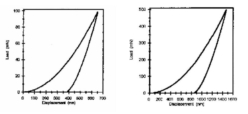 66 M.O. Adeoye and O. O. Adewoye Vo1.5, No.1 The data generated were processed using a proprietary software which converted the load and displacement in volts to load in mN and displacement in nm and corrected for load frame stiffness, thermal drift and spring constants etc. The data was examined and averaged for the ten indentations to produce the load-displacement curve for the specimens. The elastic modulus, E, and the hardness, H, were calculated with the 100 mN and 500 mN data because the indenter tip was reliably calibrated only for loads down to 100 mN and also because the tip was not ideally sharp. The tip calibration was done using single crystal )2110(− sapphire [4]. Micro-hardness tests were also performed on each of the planes to obtain the indentation size effects (ISE) plots. A Vickers square-base indenter tip was used under a load range of 100 gf to 1000 gf i.e., 1 N to 10 N. An atomic force microscope (AFM), Autoprobe M5, produced by Park Scientific Instrument, was used for the micrography and line analysis. RESULTS AND DISCUSSION The load-displacement curve for the indentations on the (0001) and }0110{ − planes of the crystal samples are shown in Figures 2 and 3 respectively. The shapes of the curves are generally similar for all loads as pointed out earlier. The analysis of each of these curves was carried out to obtain the elastic modulus and the hardness of the material (Table 1). (a) (b) Fig. 2. Load - Displacement curves obtained for the surface (0001) of tourmaline from nanoindentation experiments. The peak load for (a) is 100 mN and for (b) is 500 mN. 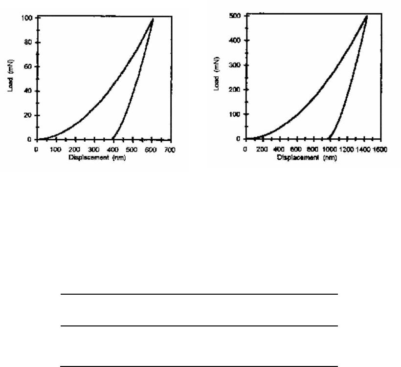 Vo1.5, No.1 Nanoindentation Study on Tourmaline 67 (a) (b) Fig. 3. Load - Displacement curves obtained for the surface )0110( − of tourmaline from nanoindentation experiments. The peak load for (a) is 100 mN and for (b) is 500 mN. Table 1. Elastic modulus, E, and hardness, H, obtained from nano-indentation experiments. Basal Plane (0001) Prismatic Plane }0110{ − E (GPa) 208.44 279.35 H (GPa) 15.6815.29 The ISE plots in Figure 4 show that plane )0110( − is harder than the (0001) plane. Also the size effect is much pronounced on the (0001) plane, leading to a cross-over of the curves below 1 N (at about 0.8 N) when extrapolated, with the (0001) plane becoming harder. This is confirmed by the results of the tests with ultra low loads showing higher hardness values for this plane, Table 1. The height profiles for the 50 mN indents on the two planes (Figures 5 and 6) revealed that the indentation depth (indicated by the markers on the profiles in Figures 5b and 6b) of the indent on (0001), 2107 Å, is less than that of the indent on )0110( − , which is 2166 Å. This indicates that the (0001) offered more resistance to indentation than the }0110{ − , i.e., the (0001) is harder than the}0110{ − . The higher hardness of surface (0001) in this regime means that it is more brittle, as shown by the lateral crack that formed at both the 50 mN and  68 M.O. Adeoye and O. O. Adewoye Vo1.5, No.1 Fig. 4. Indentation size effects (ISE) plots for the basal (0001) and prismatic }0110{ − planes of tourmaline crystal. VHN is Vickers hardness. 100 mN indentation sites (Figures 5a and 7a) while such cracks did not form at the same loads on the )0110( − (Figures 6a and 7b). These cracks formed during the unloading cycle of the indentation. It is the material’s response to the residual stresses formed when the plastic zone around the indenter tries to prevent the elastic zone from relaxing on unloading. Details of the origin of lateral cracks formed by sharp indenters have been fully discussed by Marshall et al. [19]. The indent on )0110( − , Figure 6a, also showed evidence of elastic recovery by the pin-cushion effect clearly displayed on the edges of the indentation. The elastic modulus on the basal (0001) plane is found to be lower than on the prismatic }0110{ − plane (Table 1). 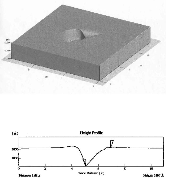 Vo1.5, No.1 Nanoindentation Study on Tourmaline 69 (a) (b) Fig. 5. (a) Atomic force micrograph of a 50 mN nano-indentation on (0001) of tourmaline in 3-dimensional perspective; (b) The height profile across the depth of the indentation. The vertical distance between the wedge-shaped markers is the depth of the indentation.  70 M.O. Adeoye and O. O. Adewoye Vo1.5, No.1 (a) (b) Fig. 6. (a) Atomic force micrograph of a 50 mN nano-indentation on )0110( − of tourmaline in 3-dimensional perspective; (b) The height profile across the depth of the indentation. The vertical distance between the wedge-shaped markers is the depth of the indentation.  Vo1.5, No.1 Nanoindentation Study on Tourmaline 71 (a) (b) Fig. 7. Atomic force micrographs of a 100 mN nano-indentation on (a) (0001) basal plane and (b) )0110( − prismatic plane of tourmaline in 3-dimensional perspective. CONCLUSION Studies of ceramics using the nanoindentation technique has proved to be very rewarding especially in the study of their mechanical properties. Ceramics are ordinarily very brittle materials but with interesting behaviour under very low loads. Planes (0001) and }0110{ − i.e., the basal and the prismatic planes respectively, are the most prominent planes in hexagonal crystals. It is known that brittle materials can flow or deform plastically under load at sufficiently high temperatures. Such plastic flow has been established on these prominent planes of tourmaline crystals under ultra low loads at room temperature, as evidenced by the indentations without fracture. Elastic deformation in this otherwise very brittle material is also confirmed by the presence of the pin-cushion effect along the edges of the indents. The prismatic plane however showed a higher stiffness than the basal plane as indicated by its higher elastic modulus. Acknowledgments — The authors thank Professor T. F. Page of Materials Division, University of Newcastle Upon Tyne, England, for allowing one of them, MOA, the use of his Ceramics Tribology Research Laboratory; and the Word Bank for providing the fund under its Staff Development Scheme. REFERENCES 1. Doerner, M. F. and Nix, W. D., J. Mater. Res., 1 (1986) 601. 2. Oliver, W. C. and Pharr, G. M., J. Mater. Res., 7 (1992) 1564. 72 M.O. Adeoye and O. O. Adewoye Vo1.5, No.1 3. Page, T. F., Oliver, W. C. and McHargue, C. J., J. Mater. Res., 7 (1992) 450. 4. Hainsworth, S. V., Ph. D. Thesis: Factors influencing the tribology of ceramic surfaces. (University of Newcastle, England. 1993). 5. Hainsworth, S. V. and Page, T. F., J. Mater. Sci., 29 (1994) 5529. 6. Field, J. S. and Swain, M. V., J. Mater. Res., 10 (1995) 101. 7. Atkinson, M., J. Mater Sci., 30 (1995) 1728. 8. Hainsworth, S. V., Bartlett, T. and Page, T. F., Thin Solid Films, 236 (1993) 214. 9. Page, T. F. and Hainsworth, S. V., Surf. and Coat. Tech., 61 (1990) 201. 10. Hainsworth, S. V. and Page, T. F., Surf. and Coat. Tech., 68 /69 (1994) 571. 11. Hay, J. L. and Pharr, G. M., in Mechanical Testing And Evaluation, eds. H. Kuhn and D. Medlin, (ASM International, 2000) pp. 232-243. 12. Henry, D. J. and Guidotti, C. V., Am. Mineralogist, 70 (1985) 1. 13. Deer, W. A., Howie, R. A. and Zussman, J., Rock-Forming Minerals Vol. 1B: Disilicates and Ring Silicates. 2nd edition. (Longman Group Ltd., London 1986). 14. Deer, W. A., Howie, R. A. and Zussman, J., An Introduction to the Rock-Forming Minerals, (Longman Scientific and Technical, England. 1992). 15. Klein, C. and Hurlburt jr., C. S., Manual of Mineralogy, (New York, John Wiley and Sons, Inc., 1993) Chapters 2 and 3. 16. Phillips, F. C., An Introduction to Crystallography, (English Language Book Society and Longman Group Limited, 1971). 17. Dietrich, R. V., The Tourmaline Group, (New York, Van Nostrand Reinhold Company, Inc., 1985) 18. Adeoye, M. O., Ph.D. Thesis: Flow and Fracture in Tourmaline and Beryl Using Indentation Techniques, (Obafemi Awolowo University, Ile-Ife. Nigeria, 1998). 19. Marshall, D. B., Lawn, B. R. and Evans, A. G., J. Am. Ceram. Soc. 65, (1982) 561. |