 Open Journal of Applied Sciences, 2012, 2, 104-109 doi:10.4236/ojapps.2012.22014 Published Online June 2012 (http://www.SciRP.org/journal/ojapps) Theoretical Derivation of Thermal Value Equations for Heating Furnaces Hainan Wu, Wenqiang Sun*, Jiuju Cai Institute of Thermal and Environmental Engineering, Northeastern University, Shenyang, China Email: *neu20031542@163.com Received March 22, 2012; revised April 19, 2012; accepted May 2, 2012 ABSTRACT Based on thermal value theory, the aim of this paper is to deduce the theoretical formulas for evaluating the energy ef- fective utilization degree in technological pyrological processes exemplified by metallurgical heating furnaces. Heat transfer models for continuous heating furnaces, batch-type heating furnaces, and regenerative heating furnaces are es- tablished, respectively. By analyzing the movement path of injected infinitesimal heat attached on steel or gas, thermal value equations of continuous, batch-type, and regenerative heating furnaces are derived. Then the influences of such factors as hot charging, gas preheating and intake time of heat on energy effective utilization degree are discussed by thermal value equations. The results show that thermal value rises with hot charging and air preheating for continuous heating furnaces, with shorter intake time when heat is attached on steel or longer intake time when heat is attached on gas for batch-type heating furnaces and that with more heat supply at early heating stage or less at late stage for regen- erative heating furnaces. Keywords: Thermal Value; Continuous Heating Furnace; Batch-Type Heating Furnace; Regenerative Heating Furnace; Energy Utilization Degree; Heat Transfer 1. Introduction When studying thermal science and engineering, two types of energy utilization processes with different char- acteristics should be clearly distinguished. One is energy conversion processes; the other is technological pyrol- ogical processes [1]. In energy conversion processes, main feedstock and product are both energetic materials; e.g., feedstock is coal and product is electric in thermal power generation process. But neither material nor prod- uct is energy in technological pyrological processes, such as metallurgical production process in which feedstock is ore and product is metal and energy is just necessary for pushing the smelting process. Traditionally, thermal efficiency has been used to evaluate the energy effective utilization degree of energy conversion processes [2,3]. However, thermal efficiency for technological pyrological process is different from that of energy conversion process [1]; and a conflict be- tween thermal efficiency and specific energy consump- tion appears in some cases [4,5]. In this paper, heating furnaces in metallurgical industry, as technological fa- cilities, are selected to study the evaluation method for energy utilization processes. To solve the conflict men- tioned above, Prof. Ren [6] proposed thermal value the- ory combining energy conservation principle and heat transfer theory to evaluate the energy effective utilization degree in technological pyrological processes. It has been extended and investigated that thermal value theory is a theory on energy-saving and production-increasing for heating furnaces [5,7]. The remainder of the paper is organized as follows: first, the definition of thermal value is briefly introduced. Then, a detailed derivation and discussion of thermal value equations is presented. Finally, conclusions are sum- marized. 2. Definition of Thermal Value Take continuous heating furnaces, as shown in Figure 1, for an example. It can be seen that most heat in the fur- naces is the chemical heat Hche released from fuel gas’s combustion. The resulting Hche can be contained in steel to be available heat Hava. In addition, Hche transfers also into other points, e.g., Hsur is lost to surroundings by thermal radiation and convection from the furnaces’ ex- ternal surface and to soil by conduction, Hspi runs away from the furnaces with off-gas at furnaces’ door and other pores, and Hcool is absorbed by cooling water. Much heat Hexh also leaves with combustion products which can be used to preheat gas. Then it converts to the physi- cal heat Hphy of gas and flows into furnace chamber once *Corresponding author. Copyright © 2012 SciRes. OJAppS  H. N. WU ET AL. 105 again. Actually, the heat contained in discharging steel is not completely meets the expectation (the superheated part Hsup is also one sort of heat losses, for example). Additionally, hot charging steel has an effective heat Hcha itself. The main purpose of heating furnaces is to heat steel to a target temperature at which the sensible heat of the steel is called target heat. Due to the loss items described above, it is impossible for each injected heat contributes to target heat completely. And the thermal value (V) of a certain injected heat is defined as the rate of the part con- tributing to target heat to the heat injected into the fur- nace. It is written as tar VH H where H is the enthalpy of injected heat, and Htar is the part contributing to target heat of H. 3. Heat Transfer Model and Thermal Value Equations 3.1. Continuous Heating Furnaces In the continuous heating furnaces (see Figure 1), gas flows in counter-flow mode with steel. The trends of gas temperature and steel temperature are given schemati- cally in Figure 2, in which tg,i and tg,o are temperatures of gas at its inlet (furnace head) and outlet (furnace end), ts,i and ts,o are temperatures of steel at its inlet (furnace end) and outlet (furnace head), and A0 is the total area of heat exchange. H che H ava sur H phy H spi H cool H exh H cha H sup Figure 1. Schematic diagram of continuous heating furnaces. ig, t og, t os, t is, t t 0 A 0 Figure 2. Model of gas-steel counter-flow heat transfer in continuous heating furnaces. For a gas-steel counter-flow heat transfer model, as shown in Figure 2, section A is assumed as any one heat transfer section, and the heat exchange area from gas inlet to section A is A. Temperatures of gas and steel at section A are respectively expressed as tg and ts. If inject a infinitesimal heat which is attached on steel at section A uniformly and steadily, local steel will have a tem- perature increase of δts under conditions of no side ef- fects such as superheat; and correspondingly, steel’s dis- charging temperature will have a temperature increase of δts,o; i.e., the (∂ts,o/∂ts) portion of the injected heat makes the steel’s temperature increase and contributes to target heat, and other (1 – ∂ts,o/∂ts) portion returns to section A by way of heat exchange. When gas moving on, the (∂tg,o/∂tg) portion of heat which has returned to section A makes the gas’s temperature increase and leaves the fur- nace with off-gas, and the (1 – ∂tg,o/∂tg) portion also re- turns to section A through heat exchange and takes part in the following heat transfer. Then the part contributing to target heat of injected heat at section A is g,o s,o s,o 0ss g 11 i i i t tt tt t so thermal value of this injected heat can be written as g,o s,o s,o s ss 11 1 g t tt Vtt t . (1) According to [5], then g0 sg g,o ggg 0 ssg 1exp 1 1, 1exp1 WkA A WW t tWW kA A WWW (2) and g sg g s,o ss gg ss 1exp 1 1, 1exp1 WkA WW W t tW WW kA WW g W (3) where k is over-all heat transfer coefficient of gas-steel and assumed as a constant, and Wg, Ws are water equiva- lent of gas and steel, respectively. Define 0,0 1,AA (4) and substitute Equations (2)-(4) into Equation (1), then thermal value equation for injected heat attached on steel is expressed as gg 0 ssg s gg 0 ssg 1exp1 1 . 1exp1 WW kA WWW VWW kA WWW (5) Copyright © 2012 SciRes. OJAppS  H. N. WU ET AL. Copyright © 2012 SciRes. OJAppS 106 Equations (5)-(8) are thermal value equations for con- tinuous heating furnace; and Equations (5) and (7) are suitable for injected heat attached on steel while Equations (6) and (8) are suitable for injected heat attached on gas. Similarly, if injected infinitesimal heat is attached on gas at section A, the (∂tg,o/∂tg) portion of injected heat will make the gas’s temperature increase and leave the furnace with off-gas; and other (1 – ∂tg,o/∂tg) portion will return to section A by means of heat exchange. As steel moving on, the (∂ts,o/∂ts) portion of the returned heat is contained in target heat, and other (1 – ∂ts,o/∂ts) portion also returns to section A by gas through counter-flow heat exchange. Then, by the same method, the thermal value (Vg) of original injected heat is rearranged as As for hot charging, it is regarded as injecting heat at steel inlet and making it be attached on cold steel; i.e., μ = 1 and Stg = Stg0. Similarly, gas preheating is upsides with injecting heat into cold gas at gas inlet, where μ = 0 and thus Stg = 0. Define g,ig,os,os,isg ,ttttWW g0 sg g gg 0 ss 1exp 11 . 1exp1 WkA WW VWW kA WWW g (6) then thermal value for hot charging (Vcha) and gas pre- heating (Vpre) are presented in Figure 3. It can be found from Figure 3 that injected heat at higher θ has higher thermal value, when other conditions being equal, especially for lower Stg0 and/or θ; thermal value increases with increasing θ, but its increase rate decreases with the continually increasing θ. Expression (kA0/Wg) in Equations (5) and (6) is a crite- rion with function of measuring dimensionless distance A0 using Wg/k. Define 3.2. Batch-type Heating Furnaces ggg00 ,.StkAWStkAWg where Stg is the Stanton number for gas, and Stg0 is the Stanton number for gas when heat exchange area is A0, Equations (5) and (6) can be rewritten as gg g0 g ss s gg g0 ss 1exp1 , 1exp1 WW St St WW VWW St WW (7) Batch-type heating furnaces’ structure diagram is shown in Figure 4. Consider a heat transfer model with constant gas temperature in the furnace; the steel’s section tem- perature difference is neglected. Followed is the modi- fied Stalk’s formula: 0g0gs ln , p mctt ttKhF (9) and g g0 g s g gg g0 ss 1exp 1 . 1exp1 WSt St W VWW St WW (8) where τ0 is heating time, m is the mass of steel, cp is the specific heat at constant pressure of steel, tg is the tem- perature of furnace gas, and t0, ts are steel temperature at initial time and τ = τ0, respectively; K is the correction coefficient considering the characteristic of heat transfer inside the thick steel, h is comprehensive heat transfer coefficient, and F is area of steel. 0.1110 100 0.0 0.2 0.4 0.6 0.8 1.0 cha θ (a) 0.1110 100 0.0 0.2 0.4 0.6 0.8 1.0 V pre θ (b) Stg0=0.03 Stg0=0.1 Stg0=0.2 Stg0=0.3 Stg0=0.5 Stg0=1 Stg0=2 Stg0=3 Figure 3. Thermal value corresponding to different values of Stg0. (a) Vcha vs. θ; (b) Vpre vs. θ.  H. N. WU ET AL. 107 According to Equation (9), heating curve of steel in batch-type furnaces is schematically shown in Figure 5. After injecting heat into batch-type furnace, Equation (9) can be rewritten as g s,i g s,o ln , p mctt ttKhF (10) where τ is the heating time with heat being injected, and ts,i, ts,o are the initial temperature and end temperature of steel with heat being injected, respectively. Inject infinitesimal heat into the model shown in Fig- ure 5 uniformly and steadily and make it be attached on steel so that local steel has a temperature increase of δts,i from ts,i and hence the end temperature of steel increases by δts,o during time-span (τ) since injecting heat. Consid- ering other conditions unchanged, during the time τ of heating process, the (∂ts,o/∂ts,i) portion of injected heat is for one part of target heat. According to the definition of thermal value, the thermal value (Vs) of the injected in- finitesimal heat is written as ss,os,i .Vtt (11) From Equations (10) and (11), it can be arrived at sexp . p VKhFmc (12) By the same method, if the uniformly injected heat is attached on gas which has a temperature increase of δtg Figure 4. Schematic diagram of batch-type heating furnaces. τ t t g t s Figure 5. Model of heating process in batch-type heating furnaces. during the heating period τ, and correspondingly, the end temperature of steel has increased by δts,o from ts,o. Dur- ing heating process of time-span τ, the [(Ws∂ts,o)/(Wg∂tg)] portion of the heat injected into gas contributes to target heat; therefore, the thermal value (Vg) of the injected infinitesimal heat is as follows: gg 1exp . p VKhFmcW s W (13) Expression (KhFτ/(mcp)) in Equations (12) and (13) is a criterion with function of measuring dimensionless time τ using (mcp/(KhF)). Define s, p St KhF mc where Sts is the Stanton number for steel, Equations (12) and (13) can be rewritten as s exp ,VS s t (14) and gs 1exp .VStW gs W (15) Equations (12)-(15) are thermal value equations for batch-type heating furnace; and Equations (12) and (14) are suitable for injected heat attached on steel while Equations (13) and (15) are suitable for injected heat at- tached on gas. Taking the heating of thin steel as an example, the re- lationship between thermal value and intake time is pre- sented in Figure 6 [7]. It can be seen that injected heat attached on steel at shorter time τ (closer to the end of heating) has higher thermal value Vs; and heat attached on gas at longer time τ has higher thermal value Vg. 3.3. Regenerative Heating Furnaces Regenerative heating furnaces have been applied and spread at home and abroad since the new century. Fur- naces of this type operate on the principle of high tem- perature air combustion (HTAC) technology and have uniform temperature in furnace hearth. The structure diagram and its simplified model are shown in Figures 7 and 8, respectively. 0.0 0.2 0.4 0.6 0.8 1.0 01234567 V V s V g Figure 6. V vs. τ. Copyright © 2012 SciRes. OJAppS 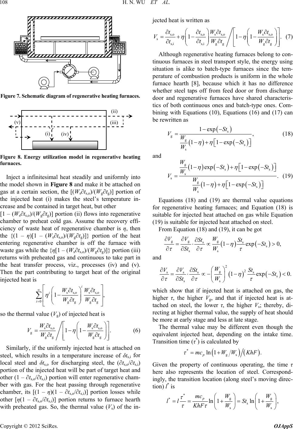 H. N. WU ET AL. 108 Figure 7. Schematic diagram of regenerative heating furaces. n (i) (ii) (iii ) (iv) (v) Figure 8. Energy utilization model in regenerative heating Inject a infinitesimal heat steadily and uniformly into th nerative furnaces. e model shown in Figure 8 and make it be attached on gas at a certain section, the [(Ws∂ts,o)/(Wg∂tg)] portion of the injected heat (i) makes the steel’s temperature in- crease and be contained in target heat, but other [1 – (Ws∂ts,o)/(Wg∂tg)] portion (ii) flows into rege chamber to preheat cold gas. Assume the recovery effi- ciency of waste heat of regenerative chamber is η, then the {(1 – η)[1 – (Ws∂ts,o)/(Wg∂tg)]} portion of the heat entering regenerative chamber is off the furnace with waste gas while the {η[1 – (Ws∂ts,o)/(Wg∂tg)]} portion (iii) returns with preheated gas and continuous to take part in the heat transfer process, viz., processes (iv) and (v). Then the part contributing to target heat of the original injected heat is ss,oss,o 0gg gg 1, i i i WtWt Wt Wt so the thermal value (Vg) of injected heat is ss,oss,o g gg gg 11 Wt Wt VWt Wt . (6) Similarly, if the uniformly injected heat is attached on steel, which results in a temperature increase of δts,i for local steel and δts,o for discharging steel, the (∂ts,o/∂ts,i) portion of the injected heat will be part of target heat and other (1 – ∂ts,o/∂ts,i) portion will enter regenerative cham- ber with gas. For the heat passing through regenerative chamber, its [(1 – η)(1 – ∂ts,o/∂ts,i)] portion losses while other [η(1 – ∂ts,o/∂ts,i)] portion returns to furnace hearth with preheated gas. So, the thermal value (Vs) of the in- jected heat is written as s,o s,os s,os s,o s s,ig gg g s,i 111 ttWt Wt VtWt Wt t . (7) Although regenerative heating furnaces belong to con- tin uous furnaces in steel transport style, the energy using situation is alike to batch-type furnaces since the tem- perature of combustion products is uniform in the whole furnace hearth [8], because which it has no difference whether steel taps off from feed door or from discharge door and regenerative furnaces have shared characteris- tics of both continuous ones and batch-type ones. Com- bining with Equations (10), Equations (16) and (17) can be rewritten as s g g s s 1exp , 11exp St VWSt W (18) and g ss s s g s s 1exp1 exp . 11exp WSt St W VWSt W (19) Equations (18) and (19) are thermal value equations for regenerative heating furnaces; and Equation (18) is suitable for injected heat attached on gas while Equation (19) is suitable for injected heat attached on steel. From Equation (18) and (19), it can be got gg g ss s ss 1exp 0,St St W VV W St St and 2 2 g sss s s ss 1exp 0. W VV StStSt St W which show that if injected heat is attached on gas, the though the eq higher τ, the higher Vg, and that if injected heat is at- tached on steel, the lower τ, the higher Vs; thereby, di- recting at higher thermal value, the supply of heat should be more at early stage and less at late stage. The thermal value may be different even uivalent injected heat, depending on the intake time. Transition time (τ*) is calculated by *ln 1mcWW gs . pKhF Given the property of continuous operating the time τ , here also represents the location of steel. Correspond- ingly, the transition location (along steel’s moving direc- tion) l* is * gg * s ss ln 1ln 1, p mc WW ll St KhF WW Copyright © 2012 SciRes. OJAppS  H. N. WU ET AL. Copyright © 2012 SciRes. OJAppS 109 Vg Vs τ l τ * l * Figure 9. V vs. τ and l. where l is the effective length of furnace. Distinguished fg furnaces, al value of heat attached on steel is higher than that on furnaces, and th he n metallurgical value equations of continuous, bat heating furnaces are derived for ents he Fundamental Research ersities (No.N090602007), [1] Z. W. Lu, “Flaical Industry Press, Beijing, 1995. ption and Performance of Reheating Fur- rom continuous heatin ther- m gas when l > l* for regenerative heating ermal value of heat attached on steel is lower than that on gas when l < l* (shown in Figure 9). 4. Conclusion By modeling theat transfer processes i furnaces, thermal type, and regenerative ch- evaluating their energy utilization degree. Based on the detailed derivation and discussion of thermal value equa- tions, it can be concluded that thermal value increases with increasing temperature of preheated gas or with hot charging for continuous heating furnaces. Injecting heat into batch-type heating furnaces to be attached on steel, thermal value is higher when intake time is closer to the end of heating; while to be attached on gas, thermal value is higher when closer to the time for supplying gas. For regenerative heating furnaces, to obtain higher thermal value, the supply of heat should be more at early stage and less at late stage. 5. Acknowledgem This work is supported by t Funds for the Central Univ China. The corresponding author also owes great thanks to Prof. Shizheng Ren for his excellent advices. REFERENCES me Furnace,” Metallurg [2] W. H. Chen, Y. C. Chung and J. L. Liu, “Analysis on Energy Consum naces in a Hot Strip Mill,” International Communications in Heat and Mass Transfer, Vol. 32, No. 5, 2005, pp. 695-706. doi:10.1016/j.icheatmasstransfer.2004.10.019 [3] C. L. Hou, G. B. Wang and J. Zhang, “Characteristics of Walking-Beam Reheating Furnace Applied in Continuous Continuous Heating Furnaces y-Saving for Continuous ation Degree of Energy in Batch-Type Casting and Rolling Line of Guofeng,” Steel Rolling, Vol. 25, No. 4, 2008, pp. 26-27. [4] W. Q. Sun, J. J. Cai and G. W. Xie, “Application Re- search on Energy-Saving of Based on Thermal Value Theory,” Proceedings of 1st In- ternational Conference on Applied Energy, Hong Kong, 5-7 January, 2009, pp. 614-620. [5] J. J. Cai, W. Q. Sun and G. W. Xie, “Thermal Value The- ory and Its Application to Energ Heating Furnace,” Journal of Northeastern University (Natural Science), Vol. 30, No. 10, 2009, pp. 1454-1457. [6] S. Z. Ren, “Heat Transfer,” Metallurgical Industry Press, Beijing, 2007. [7] W. Q. Sun, J. J. Cai, T. Du and C. Wang, “Research on Effective Utiliz Furnace Based on Thermal Value Theory”, Proceedings of 2009 International Conference on Energy and Envi- ronment Technology, Guilin, 16-19 October, 2009, Vol. 1, pp. 794-797. doi:10.1109/ICEET.2009.198 [8] W. Trinks and M. H. Mashinney, “Industrial Furnaces,” 5th Edition, John Wiley & Sons Inc., New York, 1961.
|