Paper Menu >>
Journal Menu >>
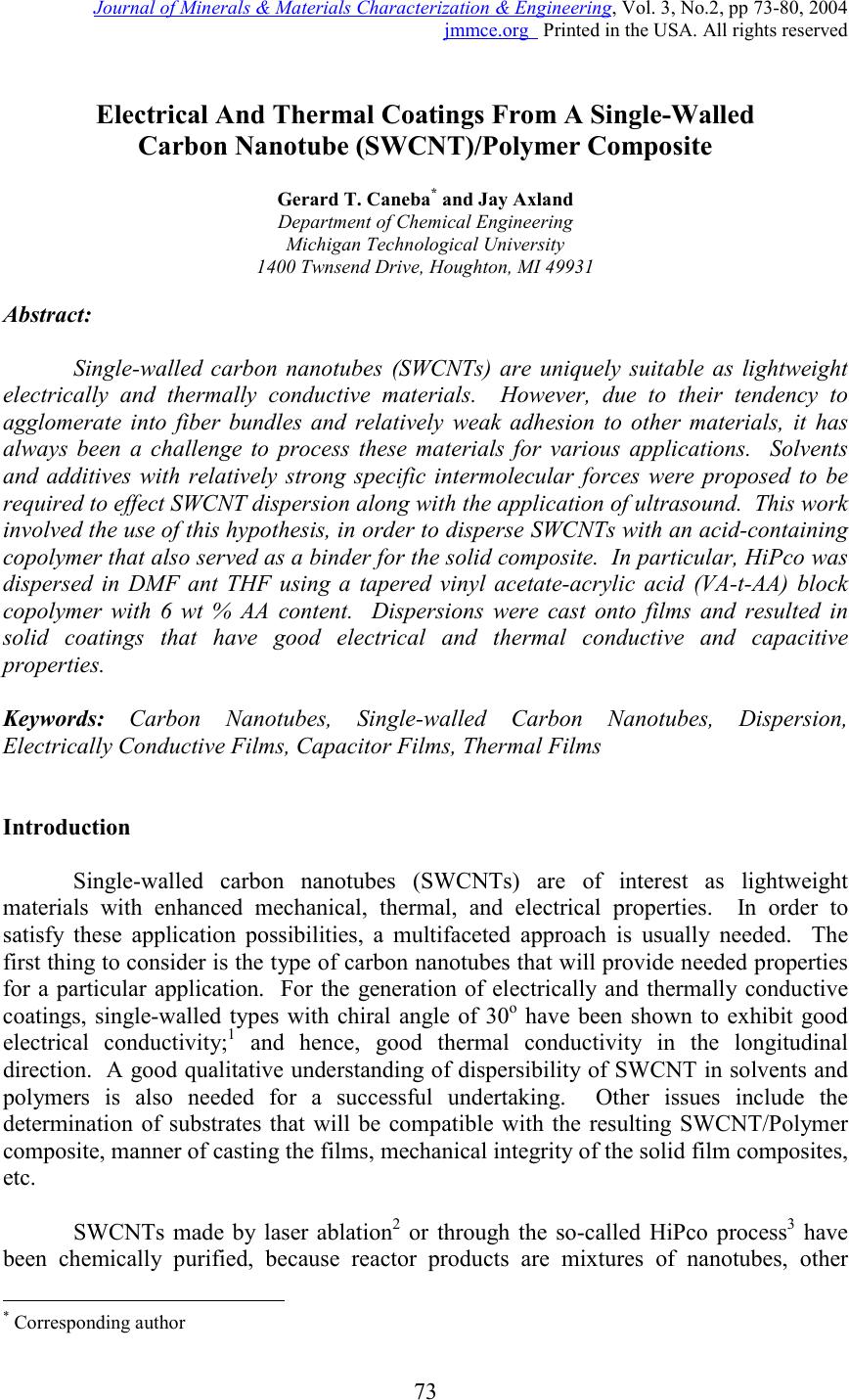 Journal of Minerals & Materials Characterization & Engineering, Vol. 3, No.2, pp 73-80, 2004 jmmce.org Printed in the USA. All rights reserved 73 Electrical And Thermal Coatings From A Single-Walled Carbon Nanotube (SWCNT)/Polymer Composite Gerard T. Caneba * and Jay Axland Department of Chemical Engineering Michigan Technological University 1400 Twnsend Drive, Houghton, MI 49931 Abstract: Single-walled carbon nanotubes (SWCNTs) are uniquely suitable as lightweight electrically and thermally conductive materials. However, due to their tendency to agglomerate into fiber bundles and relatively weak adhesion to other materials, it has always been a challenge to process these materials for various applications. Solvents and additives with relatively strong specific intermolecular forces were proposed to be required to effect SWCNT dispersion along with the application of ultrasound. This work involved the use of this hypothesis, in order to disperse SWCNTs with an acid-containing copolymer that also served as a binder for the solid composite. In particular, HiPco was dispersed in DMF ant THF using a tapered vinyl acetate-acrylic acid (VA-t-AA) block copolymer with 6 wt % AA content. Dispersions were cast onto films and resulted in solid coatings that have good electrical and thermal conductive and capacitive properties. Keywords: Carbon Nanotubes, Single-walled Carbon Nanotubes, Dispersion, Electrically Conductive Films, Capacitor Films, Thermal Films Introduction Single-walled carbon nanotubes (SWCNTs) are of interest as lightweight materials with enhanced mechanical, thermal, and electrical properties. In order to satisfy these application possibilities, a multifaceted approach is usually needed. The first thing to consider is the type of carbon nanotubes that will provide needed properties for a particular application. For the generation of electrically and thermally conductive coatings, single-walled types with chiral angle of 30 o have been shown to exhibit good electrical conductivity; 1 and hence, good thermal conductivity in the longitudinal direction. A good qualitative understanding of dispersibility of SWCNT in solvents and polymers is also needed for a successful undertaking. Other issues include the determination of substrates that will be compatible with the resulting SWCNT/Polymer composite, manner of casting the films, mechanical integrity of the solid film composites, etc. SWCNTs made by laser ablation 2 or through the so-called HiPco process 3 have been chemically purified, because reactor products are mixtures of nanotubes, other * Corresponding author  74 Gerard T. Caneba and Jay AxlandVol. 3, No. 2 carbonaceous materials, metal catalysts, etc. After purification, nanotube fibers still have a particular length distribution, which depends on the production method and purification conditions. A more significant condition for raw and purified fibers is that they are arranged in bundles held together by Van der Waals forces on the lines of contact along the fiber length. In particular, these intermolecular forces of attraction are based on a π- bond stacking phenomenon between adjacent nanotubes (or simply called π-stacking mechanism). 4 Because there can be at least hundreds of π-stacking sites between two SWCNTs, intermolecular forces are stronger than those found between two relatively small hydrocarbon molecules. However, when nanotubes are made to slide along their length, resistance is lower than what is normally found in entangled polymeric molecules. Thus, nanotubes are normally in the form of bundles, which have to be processed and/or functionalized into dispersed materials. This is especially true if the nanotubes are going to be used to reinforce polymeric materials. If other properties of nanotubes are desired even with some degradation of the overall mechanical properties, such as their excellent electrical and enhanced thermal properties, 3 then a partial level of dispersion might be good enough. In order to understand physical dispersion of SWCNTs, the molecular thermodynamics concepts 5 have to be considered. The Gibbs energy change per mole, ∆G, is a quantity that determines whether a material is soluble in a mixture. The ∆G needs to be less than zero in order to obtain miscibility in a mixture; 5 the smaller it is compared to zero, the better. The Gibbs energy change is relative to those of the pure components (SWCNT and solvent). Since the Gibbs energy change is an abstract quantity, it is represented as a relation involving the enthalpy and entropy. Thus, STHG∆−∆=∆ (1), where ∆H and ∆S are the enthalpy and entropy change, respectively. Again, both enthalpy and entropy changes are relative to their pure components. In order to obtain miscibility (or dispersibility for carbon nanotubes), ∆H should go down and/or ∆S should go up. When ∆H is brought down, other molecules that preferentially interact with the carbon nanotubes have to be present. When ∆S is brought up, a preferentially ordered structure between the carbon nanotubes and other molecules in the mixture is formed, in order to break the nanotube-nanotube ordering. Based on the above-mentioned molecular thermodynamics criteria, it should not be a surprise that hydrocarbons are not capable of dispersing carbon nanotubes. They rely mostly on dispersion forces or weak electrostatic forces (dipoles and quadrupoles), which are not stronger than the totality of those found between carbon nanotube fibers in a bundle. At the same time, they do not form persistent associated and/or solvated structures to yield an ordered molecular arrangement of some kind with the nanotubes. Water does not disperse carbon nanotubes, because it does not interact well with the nanotube surface even though it might be able to form ordered liquid structures due to its relatively strong hydrogen bonding capabilities. In order for a molecule to physically interact with the nanotube surface, it should contain π bonds to form π stacks 4 and/or it should be able to form a molecular complex (also called a π-complex 6 ) with the electron-  Vo.3, No2. Electrical and Thermal Coatings from SWCNT/Polymer Composite 75 rich nanotube surface. The latter situation happens when Lewis and protic acids are used. In terms of the formation of an ordered structure with carbon nanotubes, small molecules would have to be able to form associated structures (i.e., between like molecules) based at least on hydrogen bonding. If these associations between solvent molecules are based on anything less (such as dispersion or van der Waals forces), then the nanotubes can easily break them up. This also means that the more association sites per small molecule the better. When additives were used successfully, they normally interact strongly with the nanotube surfaces. For example, a pyrene succinimidyl ester was used successfully 4 because the pyrene group was cited to π-stack onto the nanotube surfaces. Polymeric and oligomeric materials have also been proposed to aid in nanotube dispersion and suspension. An example is poly(phenylenevinylene) or PPV, which contains aromatic groups along the backbone that interact with the carbon nanotubes through π-stacking. With sonication, wrapping of PPV has been declared to occur. 7 Another class of longchain molecules that have been found to aid the dispersibility of carbon nanotubes in water are amphiphilic surfactants, such as Sodium Dodecylsulfate (SDS), Sodium Dodecylbenzyl Sulfate (SDDBS), Sodium Octylbenzyl Sulfate, Sodium Octylbenzyl Sulfonate, Sodium Butylbenzyl Sulfonate, Sodium Benzoate, Triton X-100, Dodecyltrimethylammonium bromide (DTAB), Dextrin, and poly(styrene)-poly(ethylene oxide) (PS-PEO) diblock copolymer. 8 Actual surfactant structures around carbon nanotubes are still unknown, but again nanotube dispersion should occur based on the strong interactions between surfactant-surfactant, surfactant-solvent and solvent-solvent molecules, as well as interactions between surfactant and solvent molecules with the nanotube fibers and/or bundles. It is worth noting for the same hydrophilic group, the more effective surfactant contained phenyl groups in the hydrophobic tail. Exposure alone of carbon nanotubes, especially the SWCNT types, to thermodynamically favored compounds do not necessarily result in a dispersed carbon nanotube system. What happens is that dispersing agent molecules will interact with the outer fibers of the nanotube bundles, and no further dispersion can occur. The fibers have to be separated from one another even for a short period of time, allowing the dispersing agent molecules to form a superstructure around the fibers. Sonication has been shown to provide this kind of mechanical action at such a small area between carbon nanotube fibers. 8 Sonication involves the use of sound waves in the frequency range of 20 kHz – 10 MHz. 9 It causes the fluid to cavitate locally, followed by the collapse of cavitated bubbles. Energies involved in this phenomenon are so high that they have been found to be equivalent to a 2000-5000 K rise in local fluid temperatures and pressures up to 1800 atm inside collapsing cavities. 9 What might be significant for nanotube dispersion is the observation that when cavitated bubbles collapse from a solid surface, a jet of fluid from the opposite side of the bubble impinges onto the surface. 10 If the solid surface is made up of nanotube bundles, then this jet can force fluid molecules, additives, and nanotubes themselves to lodge between the fibers. For small molecules with weak intermolecular forces, the effect is should be marginal at best. Alternately, the same effect happens if  76 Gerard T. Caneba and Jay AxlandVol. 3, No. 2 the solvent molecules do not interact with the nanotube surface. However, if solvent molecules have strong interactions from hydrogen bonding sites and they interact with the nanotube surface, then the fluid jet forms a strong wedge between fibers to separate them. If the fluid contains polymers that are strongly interacting with its segments, with other polymeric molecules, and with the nanotube surface, then an even more stable wedge is formed. If fluid cavitation occurs behind the polymeric wedge, then the leading edge of the polymer wedge will be pulled back or around the fibers either in a clockwise or counterclockwise direction. This is probably an explanation for why polymers are found wrapped around nanotubes and/or nanotube bundles. If the above-mentioned effects of highly interacting polymers with the aid of sonication in nanotube bundles are believed to be true, then polymeric wrapping can be understood more clearly. First of all, complete polymeric wrapping of single nanotube fibers can be possible if the fibers are separated in the first place. This might happen if the fiber concentration is very dilute (in the 1 mg/L level). If the fibers are bundled up in a more concentrated solution, then, the chainlength of the polymer also plays a significant role. If the polymer is relatively long compared to the nanotube diameter, then it will wrap around entire bundles. At least the wrapped bundles are going to be separated from the main bundles, and wrapped bundles can be suspended in the fluid. If the polymer size is optimized to wrap around only a single fiber, then it is possible to separate out single fibers from solution if fiber entanglements are nonexistent. In this work, an acid-containing amphiphilic copolymer (vinyl acetate-acrylic acid tapered block copolymer) was used as a dispersion aid for HiPco in DMF and THF. Solid films were cast from the dispersion, whereby the copolymer was used as a binder for the HiPco at high concentration (50 wt % HiPco in the solid). Effectiveness of the dispersing and binding capabilities of the VA-t-AA copolymer resulted in good electrical and thermal properties of the composite coatings. Experimental Purified HiPco was dispersed in both DMF and THF with the aid of a vinyl acetate-acrylic tapered block (VA-t-AA) copolymer. The process used to produce the VA-t-AA copolymer was described elsewhere [10]. It had an acrylic acid content of 6 wt %, an average molecular weight of 30,000-40,000 Daltons, and a polydispersity index of about 2.76. Figure 1 shows a linear bead model of the VA-t- AA copolymer material. Figure 1. Linear bead model of the Vinyl Acetate (open beads) and Acrylic Acid (filled beads) segments that make up the tapered block copolymer. Bead numbers are drawn to scale to approximate molecular make-up of the VA-t-AA material with 6 wt % AA segments  Vo.3, No2. Electrical and Thermal Coatings from SWCNT/Polymer Composite 77 Preparation and Testing of the Electrical Films For the electrical composite films, a 0.1 wt % HiPco in THF was prepared using a 50-ml closed bottle. The VA-t-AA copolymer was added in such a way that there was a 1:1 wt/wt ratio between the HiPco and the copolymer. The idea is that the VA/AA copolymer can also function as a binder for the SWCNT onto relatively polar surfaces, such as wood, paper, PVC, and cellulose. An example formulation was one that contained 10 mg HiPco, 10 mg VA/AA Copolymer, and 10 ml THF, which was sonicated for 24 hrs in an ultrasonic bath that was operated at 180 Watts. Films were cast by pouring the sonicated mixture into a 4”x6” cavity comprising a Teflon™ film that was bounded by 2-mm thick polypropylene sheets. The solvent from the wet film was allowed to dry inside a fume hood for at least 24 hrs. Then, the partially dried film was vacuum-dried for at least 1 hr at 50-60 o C. Surface resistivity of the coatings were measured using a concentric electrode apparatus that was manufactured by Monro Electronics (Lyndoville, NY), Model 803A. Dry polymer and HiPco loadings per area were measured by gravimetric means, based on measured weight of the Teflon™ support per unit area. Preparation and Testing of the Thermal Films The procedure used for the preparation of thermal HiPco/VA-t-AA films was similar to that used in the preparation of electrical films. A difference was that DMF was used as a solvent. Also, sonication was done using a 240-Watt ultrasonic bath. Finally, the wet sonicated mixture was cast onto a Saran™ film and kept within a 3-inch-diameter circular cavity by a short Teflon™ tube. After drying, the film weight per unit area was obtained by cutting a rectangular piece from the uncoated Saran™ substrate, obtaining its weight using a Mettler™ balance, and then calculating its area from the length of the sides (using a digital Vernier calipher). A similar approach was done with the HiPco/VA-t-AA film on the Saran™ film substrate. The difference between the weight per area of the HiPco/VA-t-AA film onto the Saran™ substrate and that of the Saran™ substrate was the HiPco/VA-t-AA weight per unit area. Figure 2 shows the schematic diagram of the apparatus used to test the thermal generation properties of the HiPco/VA-t-AA film. A 20-Volt DC source was used to pass current across the film area. Folded Aluminum foils were used to establish contact between the alligator clips from the DC source to the HiPco/VA-t-AA film. The temperature of the film was measured by a 1/16-inch Type J thermocouple. The whole HiPco/VA-t-AA film setup was then thermally insulated by polyurethane foam blocks that were at least three inches thick. 12 VDC ##.# C Power Source Thermocouple SWCNT-Polymer Alligator Clip Connector Thermocouple Read-out Figure 2. Thermal film experimental setup  78 Gerard T. Caneba and Jay AxlandVol. 3, No. 2 Results and Discussion Electrical Films Application of dispersion of HiPco in DMF and VA-t-AA copolymer onto Teflon™ resulted in a dry coating that contained 0.059 mg HiPco per sq cm (Figure 3). Using the concentric electrode apparatus, a surface resistivity of 3.5 k- Ohms/sq was obtained. This was definitely in the conductive range of surface resistances up to 100 k-Ohms/sq. An SEM picture of the dry surface onto an Aluminum pan (Figure 4(a)) indicated the formation of well-defined ropes of SWCNT bundles, compared to the structure for pure HiPco that was dispersed in THF only (Figure 4(b)). Better definition of the structure from SEM was based on its higher electrical conductivity. Because of poor dispersion a satisfactory 4”X6” coating from the HiPco/THF mixture was not obtained. Based on these results, with the right additives, it is feasible to generate effective SWCNT-containing composites and fibers from films and coatings. In Table 1, the effect of HiPco loading on the surface resistivity is shown. It appears that an asymptote in surface resistivity is obtained as the HiPco loading is increased. This is due to the fact that the measurement is meaningful only on the surface of the composite. Figure 3. Picture of a dry coating of 1:1 wt/wt HiPco/VA-AA copolymer onto a Teflon™ film, which was found to have a surface resistivity of 3.5 k-Ohms/sq Table 1. Surface resistivity of HiPco/VA-t-AA copolymers films at different HiPco loadings HiPco Loading, mg/cm 2 Surface Resistivity, K-Ohms/sq 0.0593.50 0.2742.23 0.5572.17 (A) (B) Figure 4. Scanning electron micrographs of surfaces of HiPco coatings dispersed in THF with: (a) the aid of a VA-AA copolymer dispersing agent/binder, and (b) without the aid of a polymer dispersing agent/binder. The better definition of the rope structure in (a) indicates a higher electrical conductivity on the nanotube surface.  Vo.3, No2. Electrical and Thermal Coatings from SWCNT/Polymer Composite 79 The measurement of surface resistance of SWCNT-copolymer coatings (1:1 wt/wt) indicated readings that roughly followed an exponential decay with time. Usually, it took around 15 minutes to obtain the lowest resistance reading. For the lowest resistance reading of about 350 Ohms (corresponding to the film with 0.059 mg HiPco/cm 2 ), an initial resistance (time = 0) of about 1 k-Ohm was obtained. The lowest resistance was used to calculate surface resistivity values. In this case, the surface resistance reading of 350 Ohms was multiplied by the geometric factor of 10 to yield the surface resistivity of 3.5 k-Ohms/sq. Based on basic electrical circuit theory, the exponential decay of resistance readings occurs when a resistor is in series with a capacitor. The time constant of the decay reading is the product of the resistance and the capacitance. For a decay reading time of 15 minutes, the time constant was about 1/5 th of that, or 3 minutes (180 s). This means that the capacitance was 180 s/350 Ohms or 0.51 Farad. This was a relatively large capacitance for an SWCNT loading of 0.059 mg/sq cm in a test film area between concentric electrodes; the outer electrode was about 3.5 inches in diameter while the inner electrode was 1.9 inches in diameter. Such a large capacitance value is not surprising since SWCNTs are known to exhibit supercapacitance behavior. Thermal Film Figure 5 shows the temperature history of the thermal film during the charging phase with 20 Volts DC and discharging phase. The HiPco loading for this film was determined to be equal to 0.33 mg/cm 2 . One can see from the charging phase that the temperature went up from 22 o C to somewhere above 45 o C in 15 minutes. The discharge phase also took about the same time. This time-dependent thermal behavior follows the behavior seen in the electrical films. This means that the films also act as thermal capacitors. The use of an amphiphilic copolymer containing carboxy groups facilitated the adequate dispersion of HiPco in such a way that nanoscale super-ropes were formed in the solid films. Also, the VA portion of the copolymer acted as a binder for the HiPco, even at high loadings in the solid (50 wt % HiPco). The wider implication of this work demonstrates the possibility of using acid-containing hydrophilic-hydrophobic block or tapered block copolymers as dispersants/binders for single-walled carbon nanotubes. 0 5 10 15 20 25 30 35 40 45 50 01020304050 Time, min Film Temperature, C Charge Temperature Discharge Temperature Figure 5. Temperature history of the HiPco/VA-t-AA copolymer film  80 Gerard T. Caneba and Jay AxlandVol. 3, No. 2 Conclusion We have therefore shown that a vinyl acetate (VA)-acrylic acid (AA) tapered block copolymer (with 6 wt % AA content) is capable of adequate dispersion of HiPco in THF and DMF, and form composite films that show good electrical and thermal properties. Such a result offers the possibility of using acid-containing hydrophilic- hydrophobic block and tapered copolymers as dispersant/binder for carbon nanotubes. References 1. Moore, A.W., “Chemistry and Physics of Carbon”, Vol. 11, P.L. Walker, Jr., P.A. Thrower (Eds.), Dekker, New York, 1973, p. 69. 2. Thess, A., Lee, R., Nikolaev, P., Dai, H.J., Petit, P., Robert, J., Xu, C.H., Lee, Y.H., Kim, S.G., Rinzler, A.G., Colbert, D.T., Scuseria, G.E., Tomanek, D., Fischer, J.E., and Smalley, R.E., Science, 273, 483-7 (1993). 3. Cited in the following website – http://www.aip.org/tip/INPHFA/vol-8/iss- 6/p18.html 4. Dai et al., J. Am. Chem. Soc., 123, 3838 (2001). 5. Prausnitz, J.M., Lichtenthaler, R.N., and de Azevedo, E.G., “Molecular Thermodynamics of Fluid-Phase Equilibria”, 3 rd Ed., Prentice-Hall, New Jersey, 1999. 6. Morrison, R.T. and Boyd, R.N., “Organic Chemistry”, 4 th Ed., Allyn and Bacon, Inc. Boston, 1983, p. 338. 7. Stoddart, J.F. and Heath, J.R., Angew. Chem. Int. Ed., 40, 1721 (2001). 8. Islam, M.F., Rojas, E., Bergey, D.M., Johnson, A.T., and Yodh, A.G., Nano Letters, 3(2), 269-273 (2003). 9. Cited in the following website – http://www.fb-chemie.uni- rostock.de/ess/sonochem_intro.html 10. G.T. Caneba and Y.L. Dar, “Free-Radical Retrograde Precipitation Copolymers and Process for making the Same”, submitted to U.S. Patent and Trademark Office. Acknowledgements We acknowledge NASA-Johnson Space Center (Houston, Texas) for the summer fellowship for G. Caneba, which provided the facilities for the application of the vinyl acetate-acrylic acid tapered block copolymer onto single-walled carbon nanotubes (Summer, 2003). This work was also partially funded by the National Science Foundation, through the Nanoscale Undergraduate Education (NUE) Program (NSF #0304439). |