Paper Menu >>
Journal Menu >>
 Journal of Minerals & Materials Characterization & Engineering, Vol. 3, No.1, pp 23-31, 2004 jmmce.org Printed in the USA. All rights reserved Effect of Particle Size of Filler on Properties of Nylon-6 Suryasarathi Bose and P.A.Mahanwar * Plastics & Paints Division University Institute of Chemical Technology, University of Mumbai, Matunga, Mumbai-400 019, India. Phone: 91-22-24145616 Fax: 91-22-24145616. * E-mail: pmahanwar@yahoo.com E-mail: bose154@rediffmail.com Particulate reinforced thermoplastic composites are designed to improve the properties and to lower the overall cost of engineering plastics. In this study the effects of adding mica with variable particle size on the mechanical, thermal, electrical and rheological properties of nylon-6 was investigated. Composites of nylon-6 with varying concentrations (viz. 5 to 40 weights %) of mica were prepared by twin screw extrusion. The composite showed improved mechanical, thermal as well electrical properties on addition of filler. It is also observed that mechanical properties, electrical properties as well as thermal properties increases with decrease in particle size. Key Words: Particulate composites, nylon-6, mica, filled nylon properties. 1. INTRODUCTION Particle filled polymer composites have become attractive because of their wide applications and low cost. Incorporating inorganic mineral fillers into plastic resin improves various physical properties of the materials such as mechanical strength, modulus and heat deflection temperature 1 . In general the mechanical properties of particulate filled polymer composites depend strongly on size, shape and distribution of filler particles in the matrix polymer and good adhesion at the interface surface. Nylons 2 are among the most widely used engineering thermoplastics in automobile, electrical, electronic, packaging, textiles and consumer applications because of their excellent mechanical properties. However, limitations in mechanical properties, such as low heat deflection temperature, high water absorption and dimension instability of pure nylons have prevented their application in structural components. Hence numerous efforts have been undertaken to use nylons as matrix resins in composites by adding inorganic fillers such as aluminatrihydrate, montmorrilonite, clays, talc, mica, silica, flyash, wollastonite, kaolin etc. In this investigation mica of variable particle size was added to nylon-6. Influences of the addition of these fillers on the mechanical, thermal, rheological and electrical properties were examined.  24 Suryasarathi Bose and P.A.Mahanwar Vol. 3, No. 1 2. EXPERIMENTAL 2.1 Experimental Plan The schematic representation of experimental plan is shown in the following figure: Base resin Fillers (Predried, 80 O C ) (Predried, 80 O C) Dry mixing Additives Melt mixing (APV twin-screw extruder) Pelletization Injection moulding Testing of samples Ø Mechanical Ø Thermal Ø Rheological Ø Electrical 2.2 Material used Material used are listed in the following table: Material used Function Grade Supplier Nylon-6 Polymer matrix Nirmide E 35 M/sNirlon India Limited Mica Filler Water ground(75µ) M/s BS Mica,Mumbai,India Mica Filler Dry ground(37 µ) M/s HMP,Mumbai,India Finnawax Dispersing agent FinnawaxSS M/s Fine Organics,Mumbai,India ------------ Antioxidant Irganox 1076 M/s CIBA,Mumbai,India ------------ Heat Stabilizer Irgafos168 M/s CIBA,Mumbai,India  Vo1. 3, No. 1 Effect of Particle Size of Filler on Properties of Nylon-6 25 2.3 Compounding Before compounding, the fillers were dried at 80 o C for 8 hours in an air circulated oven and then dry mixed with nylon-6 and other additives. Composition shown in the table was mixed and extrudated in a co-rotating twin extruder (APV Baker Ltd. England).The L/D ratio of the screw is 25:1.Mixing speed of 60 rpm was maintained for all the compositions. The extrudates from the die were quenched in a tank at 20-30 o C and then palletized .In all the above set of experiments 1.5% of dispersing agent, 1% each of antioxidant and heat stabilizing agents were mixed. For the melt blending the temperature profile of the extrusion were Zone 1(205 0 C) Zone 2(235 0 C) Zone 1(245 0 C) Zone 1(255 0 C) and Die (265 0 C). The extrudates of the compositions shown in the table above were palletized in Boolani’s pelletizing machine. The rpm of the pelletizer was maintained between the ranges of 60-80. 2.4 Injection Molding The granules of the extrudates were predried in an air circulated oven at 80 0 C for 8 hours and injection molded in a microprocessor based Boolani’s injection moulding machine fitted with a master mould containing the cavity for tensile strength, flexural and impact specimens. After its ejection from the mould, specimens were cooled in ice–water. Processing parameters are Zone 1(200 0 C) Zone 2(235 0 C) Zone 1(260 0 C). 2.5 Characterization 2.5.1 Mechanical properties Tensile strength as per ASTM D 638 M91 was evaluated using universal tensile testing machine LR50k from Lloyd instruments Ltd.,U.K at a crosshead speed of 50mm/min. Flexural properties according to ASTMD790 were tested using LR 50K from Lloyd instruments Ltd., U.K. Izod impact test were carried out using an Avery Denison impact tester (ASTM D 256-92). A 2.75J energy hammer was used and the striking velocity was 3.46m/sec. For Izod impact test specimens the notch was cut using a motorized notch-cutting machine (Rayran U.K). The unit of expression is J/m. 2.5.2 Thermal properties Heat Distortion temperature was measured using Vicat Softening Point machine, Davenport, UK (ASTM D 1525, D648). The sample position was edgewise, test span was 100mm and surface stress was 1820KPa (264psi). 2.5.3 Electrical properties Dielectric strength was measured by Zaran electrical instruments, India. 2.5.4 Rheological properties Shear viscosity (at 0.1sec -1 shear rate and 250 0 C) of different compositions were measured using Haake RT 10 Rotovisco (Germany) parallel plate viscometer. 3.0 RESULTS AND DISCUSSION 3.1 Tensile properties  26 Suryasarathi Bose and P.A.Mahanwar Vol. 3, No. 1 Fig. 1 shows the variation of tensile strength with filler concentration of mica. There was a significant increment in the strength as the filler loading increased larger mica particle sizes showed higher increments. The increment may be due to the platy structure of the mica filler providing good reinforcement. Elongation properties as seen from Fig. 2 decreased with the presence of filler that indicates an interference 4 by the filler in the mobility 5 or deformability of the matrix. This interference was created through the physical interaction and immobilization 6 of the polymer matrix by imposing mechanical restraints. Figure 1. Variation of the Tensile Strength of Nylon 6 with Filler Content Variation of the elongation at break of nylon 6 with wt% of filler content 0 10 20 30 40 50 60 70 80 01020304050 filler content(wt%) Elongtion at break(%) mica(37microns)mica(75microns) Figure 2. Variation of the Elongation at Break of Nylon 6 with Filler Content Variation of the tensile strength of nylon 6 with filler content in wt% 58 60 62 64 66 68 70 01020304050 filler content(wt%) Tensile strength(MPa) mica(75microns)mica(37microns)  Vo1. 3, No. 1 Effect of Particle Size of Filler on Properties of Nylon-6 27 3.2 Flexural properties Fig. 3 depicts the variation in flexural modulus with varying concentrations of mica. The flexural modulus increased with the increase in filler concentration of mica. The rate of increase of flexural modulus was comparable to the increase in concentration of mica and the increase in particle size. Thus it was confirmed that the total area available to deformation stress 9 played an important role. Fig. 4 presents the variation in flexural strength. It is seen that flexural strength 10 increased with the increase in concentration of filler. Figure 3. Variation of the Flexural Modulus of Nylon 6 with Filler Content Figure 4. Variation of the Flexural Strength of Nylon 6 with Filler Content Variation of the flexural modulus of nylon6 with wt% of filler content 0 1000 2000 3000 4000 5000 6000 010203040 filler content(wt%) flexural modulus(MPa) mica(37microns)mica(75microns) Variation of the flexural strength of nylon6 with wt% of filler content 0 25 50 75 100 125 01020304050 filler content(wt%) flexural stength (MPa) mica(37microns)mica(75microns)  28 Suryasarathi Bose and P.A.Mahanwar Vol. 3, No. 1 3.3 Impact properties Fig. 5 illustrates the variation of impact strength with filler by weight percentage. It is clear from this figure that the strength increment 12 at low weight percentage of filler may be attributed to the formation of small sized crystallites, i.e. spherulites, as well 13 as the capacity to absorb more energy by increased portion of matrix. A further increase in weight percentage reduced the deformability of the matrix, and, in turn, reducing the ductility 15 in the skin area so that the composite tended to form a weak structure. Figure 5. Variation of the Impact Strength of Nylon 6 with Filler Content 3.4 Thermal properties Heat distortion temperature Fig. 6 illustrates the variation of heat distortion temperature with varying filler percentage. It is clear from this figure that the heat distortion temperature increased steeply with the increase in filler loading. A significant increase in heat distortion temperature was expected because inorganic fillers have high thermal stability. Lower particle size of mica resulted in higher heat distortion. This was attributed to the increase in interstitials volume or the increase in matrix filler surface contact. Variation of the impact strength of nylon 6 with weight% of filler content 0 50 100 150 01020304050 filler content (wt%) Impact strength(J/m) mica(37microns)mica(75microns)  Vo1. 3, No. 1 Effect of Particle Size of Filler on Properties of Nylon-6 29 Figure 6. Variation of the Heat Distortion Temperature of Nylon 6 with Filler Content 3.5 Electrical properties Dielectric strength It is clear from Fig. 7 that the dielectric strength 14 increased with the increase in filler concentration and attained maxima. At higher filler loading the dielectric strength values remained constants with the increase in filler but the dielectric strength values were higher for larger particles as compared to small particle sizes. The trend in variation of dielectric strength in mica was attributed to the total surface area available based on the dispersion of filler particles at a lower loading. At higher loading the dispersion of platy structure is impeded and hence the total strength gets reduced. Figure 7. Variation of the Dielectric Strength of Nylon 6 with Filler Content Variation of the heat distortion temperature of nylon 6 with wt% of filler content 0 100 200 300 01020304050 filler content(wt%) Heat distortion temperature(C) mica(37microns)mica(75microns) Variation of the dielectric strength of nylon 6 with weight% of filler content 5 7 9 11 13 15 010203040 filler content(wt%) Dielectric strength(kV/mm) mica(37microns)mica(75microns) 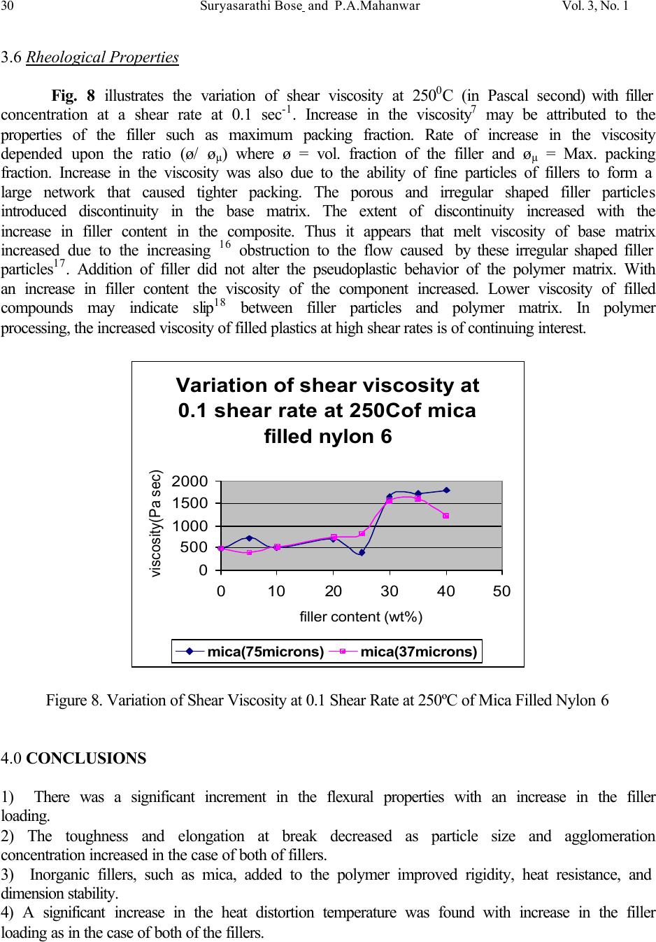 30 Suryasarathi Bose and P.A.Mahanwar Vol. 3, No. 1 3.6 Rheological Properties Fig. 8 illustrates the variation of shear viscosity at 250 0 C (in Pascal second) with filler concentration at a shear rate at 0.1 sec -1 . Increase in the viscosity 7 may be attributed to the properties of the filler such as maximum packing fraction. Rate of increase in the viscosity depended upon the ratio (ø/ ø µ ) where ø = vol. fraction of the filler and ø µ = Max. packing fraction. Increase in the viscosity was also due to the ability of fine particles of fillers to form a large network that caused tighter packing. The porous and irregular shaped filler particles introduced discontinuity in the base matrix. The extent of discontinuity increased with the increase in filler content in the composite. Thus it appears that melt viscosity of base matrix increased due to the increasing 16 obstruction to the flow caused by these irregular shaped filler particles 17 . Addition of filler did not alter the pseudoplastic behavior of the polymer matrix. With an increase in filler content the viscosity of the component increased. Lower viscosity of filled compounds may indicate slip 18 between filler particles and polymer matrix. In polymer processing, the increased viscosity of filled plastics at high shear rates is of continuing interest. Variation of shear viscosity at 0.1 shear rate at 250Cof mica filled nylon 6 0 500 1000 1500 2000 01020304050 filler content (wt%) viscosity(Pa sec) mica(75microns)mica(37microns) Figure 8. Variation of Shear Viscosity at 0.1 Shear Rate at 250ºC of Mica Filled Nylon 6 4.0 CONCLUSIONS 1) There was a significant increment in the flexural properties with an increase in the filler loading. 2) The toughness and elongation at break decreased as particle size and agglomeration concentration increased in the case of both of fillers. 3) Inorganic fillers, such as mica, added to the polymer improved rigidity, heat resistance, and dimension stability. 4) A significant increase in the heat distortion temperature was found with increase in the filler loading as in the case of both of the fillers.  Vo1. 3, No. 1 Effect of Particle Size of Filler on Properties of Nylon-6 31 5) Addition of filler did not alter the pseudoplastic behavior of the polymer matrix. With increase in the filler content the viscosity of the composites increased. 6) There was a significant increase in the dielectric strength. 7) The mechanical properties of the composite were found to be a function of the particle size, aspect ratio, the dispersion, the particle orientation, the interfacial interaction between the minerals and the polymer matrix. Platy filler such as mica gave significant improvement in stiffness. 5.0 REFERENCES 1) Maiti,S.N; Lopez,B.H; J.Appl Polym Sci, 44,353(1992). 2) Kohan, M.I., Nylon Plastics , Hanser ; New York(1973). 3) Jankar, J; Kucera ,J; Polym Eng Sci , 30,707(1990). 4) He ,D; Jiang, B; J. Appl Polym Sci, 49,617(1993). 5) Unal, H; Findik, F; J . Appl Polym Sci, 88,1694(2003). 6) Jingxin, L; Rong, Z; J. Polym Eng Sci, 40,1529(2000). 7) Mitra, I; Elsi, M; Rheo, 36,1992. 8) Gahleitener, M ; Neibl, W; J. Appl Polym Sci, 53,283(1994). 9) Tavman, L. H; J. Appl Polym Sci, 62,2161(1996). 10)Liu, Z; Gilbert, M; J .Appl Polym Sci, 59,1087(1996). 11)Michel, A; Patric, G; Pierre,G; J.Appl Polym Sci, 39,1130(1999). 12)Hattotuwa, G. B; Ismail, H; Polymer Testing, 21,833(2002). 13) Masahiro, N; Yasuharu, F. V; J. Appl Polym Sci, 79,1693(2001). 14)Theraja.B,L; Theraja, A. K; A Textbook Of Electric Technology, 1,1993. 15) Qui,W; Mal, K; Zeng, H; J.Appl Polym Sci, 77,2974(1999). 16) Ramos, M; Berna, M. S; J. Polym Eng Sci, 31,245(1991). 17)Han,C,D, Stanford,D, Yoo,H,Y; J. Polym Eng Sci 18,849(1978). 18) Modern Plastics Encyclopedia Handbook; Mc Graw Hill; New York,1994. |