Paper Menu >>
Journal Menu >>
 Journal of Minerals & Materials Characterization & Engineering, Vol. 3, No.1, pp 1-12, 2004 jmmce.org Printed in the USA. All rights reserved 1 Characterization Of Graphite Particle Shape In Spheroidal Graphite Iron Using A Computer-Based Image Analyzer *B. I. Imasogie and **U.Wendt *Department of Metallurgical and Materials Engineering Faculty of Technology Obafemi Awolowo University, Ile-Ife, Nigeria. E-mail: imasogie@oauife.edu.ng, imasogie2002@yahoo.co.uk Tel.: +234-803-711-6415 Fax: 14435860735, 16266083759 ** Institut für Werkstofftechnik und Werkstoffprüfung Technische Universität Magdeburg, Germany. E-mail: Ulrich.wendt@masch-bau.uni-magdeburg.de Tel.: 0391-67-14542 Fax: 0391-67-14569 A procedure and specification for evaluating the degree of spheroidization of graphite in spheroidal graphite iron (SGI), using a computer-based image analyzing system has been developed as an aid to structure-property-quality assessment. Both global and feature-specific numerical indices have been programmed and implemented using a Zeiss Jenaphot 2000 projection microscope and SEM interfaced to a computer-based MACROS III analyzer and a CCD video camera. The modular procedure has been tested and used to evaluate the effect of variation in the degree of spheroidization of graphite on the 0.2 % offset yield strength for an iron series ranging from ASTM type I (fully nodular) to ASTM type II-III-IV (mixtures of nodular and compacted/vermicular graphite) and were found to indicate good correlation. Keywords: Spheroidal graphite iron (SGI), graphite morphology, characterization, image analysis. INTRODUCTION Spheroidal (nodular or ductile) graphite iron; SGI, has an as-cast structure containing graphite particles in the form of small rounded, “spheroidal”, “globular” or “nodular” particles in a ductile metallic matrix. It has been established that all of the mechanical and physical properties characteristic of SGI are a result of the graphite being substantially or wholly in the spheroidal/nodular shape such that its bulk physico-mechanical properties are determined primarily by the steel-like matrix. Any departure from this shape or a proportion of the graphite will cause a drastic deviation from these properties [1-4]. Occasionally, a consistent spheroidal type of graphite is not obtained in regular production of ductile iron. This may result from insufficient or excessive nodulariser, or non-uniform treatment or the  2 B. I. Imasogie and U. Wendz Vol. 3, No.1 presence of inhibiting elements. Also, the problem may be the choice of nodulariser, mode of addition, and environmental and/or human considerations. However, unlike other renowned engineered materials, requirements concerning graphite “spheroidicity” in SGI seldom appear in users’ specifications. In essence, commercial SGI castings are designed on the basis of their properties and rarely on the basis of their graphite morphology, shape or structure. Graphite nodularity, usually evaluated by visual assessment, might be utilized as a simple form of selection for castings to determine which should and should not be accepted [5]. The adoption of a uniform and universally acceptable structure-property specification for SGI by international standard organizations and societies is still a long way in the future. For now, the techniques used in assessing the graphite nodularity or spheroidicity in commercial SGIs have included visual assessment of structure and recently, the use of special image analyzing microscopes and NDT. The use of visual assessment was subjective, restricted to small areas of observation and relied heavily upon the skill of the operator (and the sensitivity of the equipment used), since it was necessary to recognize and evaluate subtle changes in the form and amount of non-nodular graphite and in the matrix structure which were difficult to quantify but which are easily measured through the use of special projection microscopes, SEM and/or NDT. However, what is clear from the work of several researchers [4-5] is that graphite form cannot be directly measured by any non-destructive tests. The use of computer-based image analyzing microscopes, solely or in complement with NDT (ultrasonic, sonic, eddy current, etc) has a unique advantage in that it is possible to measure a much wider range of parameters related to graphite form and they can be used to evaluate the bulk properties of the casting. The present work was aimed at developing and testing a simple, full-proof and reproducible method of assessing the graphite in SGI to replace the rather subjective visual assessment method and improve on some of the present 2-dimensional image analysis procedures. This paper describes the design, specification and adaptation of routines for evaluating the graphite morphology and/or shape in deep-etched (to reveal the 3-D morphology) as-cast iron series using universally accepted definitions for particle shape analysis. The approach allows parameters to be determined via projections or planar sections in a three-dimensional context and relate the graphite structure, to properties of the castings. Since 0.2 % offset yield strength is the property used in casting design, it is necessary to gauge what proportion of non-spheroidal graphite could be tolerated in castings without serious effect upon their performance in service. Data presented in this paper shows the effect of variable degrees of spheroidization of graphite on the 0.2 % off-set yield strength for an iron series that produced a broad spectrum of graphite forms, ranging from ASTM type 1 (fully spheroidal) to mixtures of spheroidal and ASTM types III-IV (compacted/vermicular and spiky graphite). AN OVERVIEW OF GRAPHITE NODULARITY ASSESSMENT PROCEDURES It is a common practice in the field of shape analysis to specify at least two different shape parameters, the first one being a global measure of the particle and the second, concentrating on its morphological details [6]. For graphite particles in the hue of compacted/vermicular, near-nodule and spheroids in cast iron, several parameters have been defined, each serving different purposes in relation to particular properties or features [7-9]. In the special case of SGI, what is needed is a good descriptor that would give a vivid or an all encompassing categorization (or characterization) of deviations from a completely  Vol. 3, No. 1 Characterization of Particle Shape using a Computer-based Image Analyzer 3 spheroidal graphite to forms such as spiky, chunky, fern-like, doughnut, cabbage, stubby, wormy, crab, octopus, irregular spheroids, near/semi-nodule, etc. The descriptor should also indicate the potency or suitability of the graphite nodulariser/modifier used and the treatment practice. In order to eliminate the effect of pseudo-nodules, some researchers [9-10] have recommended the combination of several shape factors in order to adequately describe the graphite morphology and/or form. Ledbetter and Datta [11] using a scattered-plane-wave ensemble -average model, represented graphite particles as biaxial ellipsoids where the aspect ratio varies from zero (oblate-disc limit) to unity (spherical limit). The model considers three of the geometrical properties of the inclusions: volume fraction, shape (sphere to disc) and orientation. Pundale et al [12] using the 2-D surface imaging technique has shown that the minimum roundness (a measure of nodularity) for which graphite is considered nodular is 65 %. Using finite element modeling, an approach to model the effect of decreasing roundness was described. Decreasing the ratio of the semi-major axis (a) to semi-minor axis (b) from 1 to 0.25 changes the roundness from 100 to 64 %. Hence, the effect of shape (roundness) can be modeled by considering various b/a ratios. Machalikova et al [10] proposed and attempted to verify a method for the evaluation of the graphite shape in cast iron using an automatic image analyzer. The problem with this procedure, as with the other similar ones mentioned above, was that it could only be implemented on two-dimensional polished specimen surfaces, which like the rather subjective visual assessment technique, does not adequately take into account the “total” graphite structure. They proposed instead the combination of several shape parameters in order to adequately evaluate and correlate the graphite form with the measured mechanical properties. From the foregoing, it is clear that the 2-D shape factor or profile method cannot adequately distinguish the effects of graphite morphology on mechanical properties. Recently, Li et al [13] presented three methods to measure the irregularity of graphite nodule in one-, two- and three-dimensional space and showed that the measured length on the boundaries of graphite nodules in SGI obeys Richardson’s fractal equation, with the fractal dimension being a more sensitive parameter influencing mechanical properties than any 2-D shape factor. Using a variation-correlation method applied to the quantitative description of the 3-D graphite surfaces, it was shown that the fractal dimension could be used to characterize the irregularity of graphite surfaces processed by different inoculation methods. The shape factor or profile method was found to be less appropriate for the quantitative analysis, being as mentioned above, a 2-dimensional analysis. However, the use of fractal theory is novel in quantitative analysis, and has not been sufficiently developed to take care of the myriad of problems associated with the characterization of graphite in SGI. In particular, although spherical particles have been described as fractal, they however possess self-similarity over only a narrow range of length scales [14]. For such objects, ideal fractal scaling laws may require substantial corrections. Thus the major limiting factor to the fractal approach is that the boundaries of the graphite nodules meander and obstruct view, necessitating the use of correcting laws and/or equations. This condition may be due to the experimental difficulty in measurement of area [15]. As expected, when the ruler length becomes very large, the small and fine structures of the boundaries may be missed out in measurement, leading to a rapid decrease in the measured length. Also, the fractal theory method is predicated on the assumption that the graphite particle is isotropic, making it possible to approximate the fractal dimension of the 3-D graphite nodule to that measured for the 2-D observation plus 1. There is evidence to show in some cases, as revealed in deep- etched SGI specimens, that colonies of graphite spheroids exist that appears to be built up of several tiny spherulites [3]. The surface of such nodules appears spongy while the spheroids themselves appear to be randomly distributed and oriented in the matrix such that no definite  4 B. I. Imasogie and U. Wendz Vol. 3, No.1 plane of location exists. In other known cases [16], the graphite appears lumpy and solid with a relatively rough surface. Thus, graphite nodules with the same or close values of shape factor may have different fractal dimensions. Among emerging quantitative methods of particle description, the approaches using a combination of Fourier analysis [17] and the concept of fractal harmonies [18] seem to be the best suited with regard to particle characterization, but there is an almost complete lack of experience in this field. The problem, as with the fractal theory method mentioned above, is the fact that it is based on a 2-D image or its contour line, which is much easier to obtain than from a 3-D image. However, the information obtained from a single particle is a statistical one in analogy with statistical diameters, and hence, a higher sample population will be needed to obtain the same statistical reliability of information than with a 3-D analysis. Nevertheless, 3-dimensional structural information can often be inferred from 2-D projections, given some additional information on the shape of the particles. Such information can be garnered in the case of SGI if deep-etched specimens are used in the characterization analysis, in order to properly evaluate the ‘total’ particle structure. Thus, to get a reasonable quality assessment of graphite structure, it is necessary to define a technique that provides a measurement of subtle changes in graphite form and amount and relate same to specific design properties of the casting. The degree of spheroidisation, the D.S. parameter, as defined and implemented in this work has been confirmed [3,16,19] to adequately serve the purpose of evaluating graphite form better than those mentioned above. By its definition, it satisfactorily indicates for every graphite particle, the degree of smoothness, sphericality, elongation or slimness, extent, solidity, convexity and branching; with reference to a complete sphere. This parameter was first proposed by Tsutsumi and Imamura [20] and measured by Tsutsumi et al [21] using an image-analyzing computer. However, there are recognizable limitations in the technique used, particularly in the preparation of the specimens to the required standard of the surfaces to be examined. Again, being a purely two- dimensional profile or surface analysis, it would be difficult to gauge the extent to which misleading results might be obtained as a result of variation in structure at such a surface, in relation to the bulk material. Thus, the procedure is useful only as a check that a very high proportion of the graphite has a good nodular (with a circle as reference in this case) form or if the form of the non-nodular graphite is always similar. Previous experience [3, 16, 19] confirmed in this work, shows that by deep etching (with the matrix etched away to reveal the 3-dimensional form of the graphite) and subsequent examination using a stereo projection microscope (to take care of the projected height and structure of graphite particles) and complemented with data from SEM interfaced to a computer based image analyzer, the complete feature specific three-dimensional form of fully nodular or spheroidal [3], fairly nodular (near-nodule) [16] and non-nodular graphite forms (compacted/vermicular) [19]; as illustrated by Figures 1a, b and c, respectively can be adequately quantified. More importantly, the deep-etched 3-D morphology enables the proper delineation or isolation of each particle so that their extent, branching/connectivity, irregularity or otherwise can be adequately taken care of in analysis. The major advantage of this approach therefore, is that it provides useful information based on an entire elevation map of the graphite structure, which relies on a 3-dimensional stereo image evaluation using projection and/or scanning electron microscopes interfaced to image analytical systems. 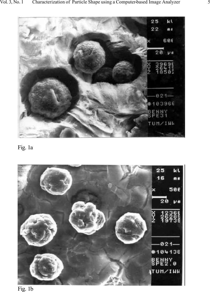 Vol. 3, No. 1 Characterization of Particle Shape using a Computer-based Image Analyzer 5 Fig. 1a Fig. 1b 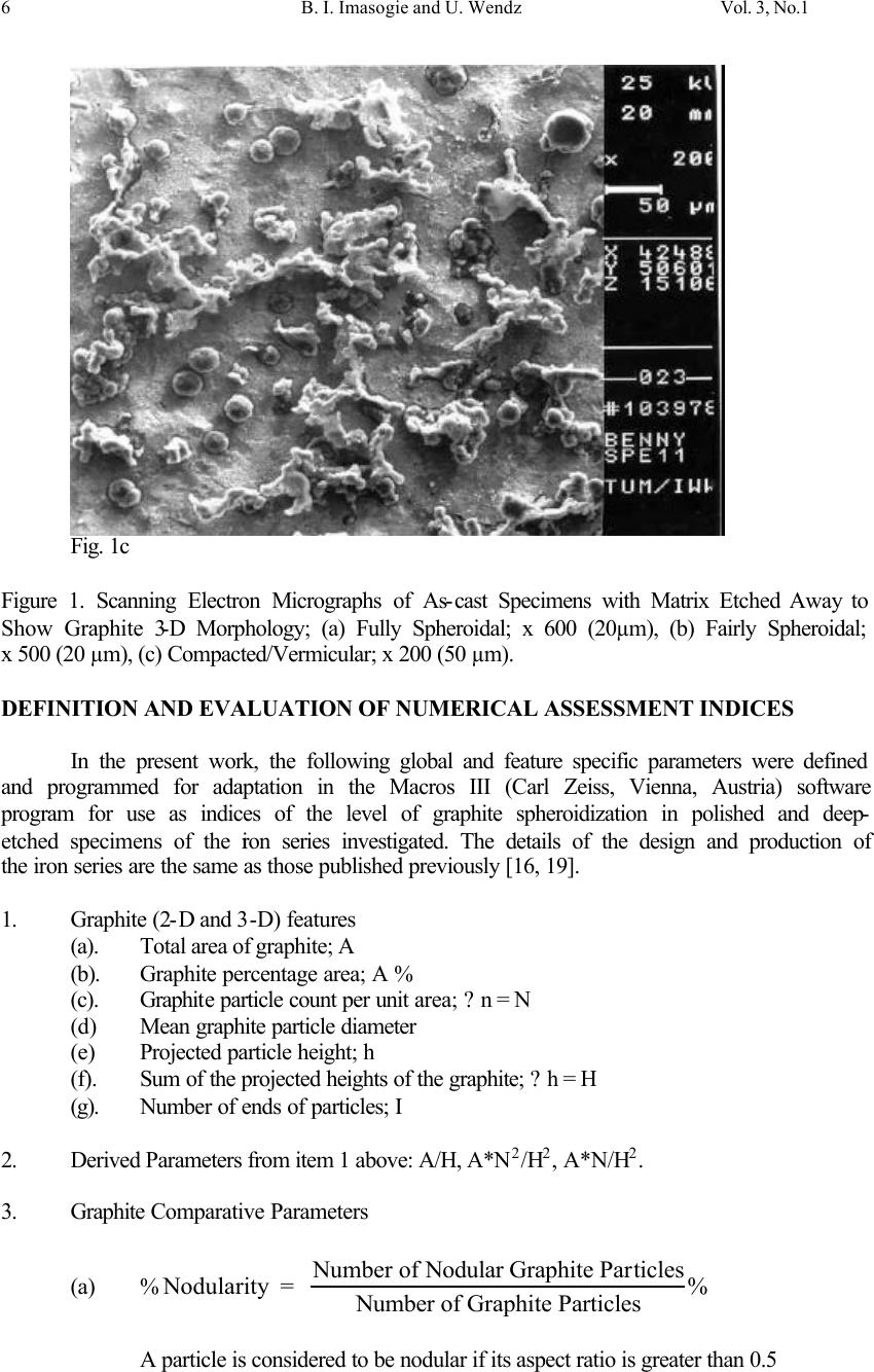 6 B. I. Imasogie and U. Wendz Vol. 3, No.1 Fig. 1c Figure 1. Scanning Electron Micrographs of As-cast Specimens with Matrix Etched Away to Show Graphite 3-D Morphology; (a) Fully Spheroidal; x 600 (20µm), (b) Fairly Spheroidal; x 500 (20 µm), (c) Compacted/Vermicular; x 200 (50 µm). DEFINITION AND EVALUATION OF NUMERICAL ASSESSMENT INDICES In the present work, the following global and feature specific parameters were defined and programmed for adaptation in the Macros III (Carl Zeiss, Vienna, Austria) software program for use as indices of the level of graphite spheroidization in polished and deep- etched specimens of the iron series investigated. The details of the design and production of the iron series are the same as those published previously [16, 19]. 1. Graphite (2-D and 3-D) features (a). Total area of graphite; A (b). Graphite percentage area; A % (c). Graphite particle count per unit area; ?n = N (d) Mean graphite particle diameter (e) Projected particle height; h (f). Sum of the projected heights of the graphite; ?h = H (g). Number of ends of particles; I 2. Derived Parameters from item 1 above: A/H, A*N 2 /H 2 , A*N/H 2 . 3. Graphite Comparative Parameters (a) % Nodularity = Number of Nodular Graphite Particles Number of Graphite Particles % A particle is considered to be nodular if its aspect ratio is greater than 0.5 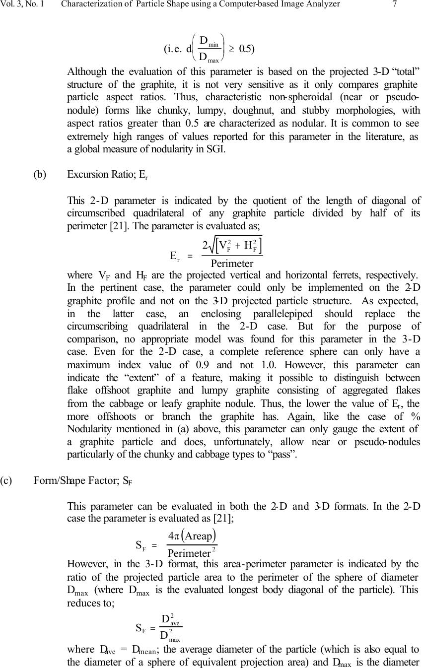 Vol. 3, No. 1 Characterization of Particle Shape using a Computer-based Image Analyzer 7 (i.e. d D D min max ≥ 05.) Although the evaluation of this parameter is based on the projected 3-D “total” structure of the graphite, it is not very sensitive as it only compares graphite particle aspect ratios. Thus, characteristic non-spheroidal (near or pseudo- nodule) forms like chunky, lumpy, doughnut, and stubby morphologies, with aspect ratios greater than 0.5 are characterized as nodular. It is common to see extremely high ranges of values reported for this parameter in the literature, as a global measure of nodularity in SGI. (b) Excursion Ratio; E r This 2-D parameter is indicated by the quotient of the length of diagonal of circumscribed quadrilateral of any graphite particle divided by half of its perimeter [21]. The parameter is evaluated as; [ ] E 2V Perimeter r F 2 = + H F 2 where V F and H F are the projected vertical and horizontal ferrets, respectively. In the pertinent case, the parameter could only be implemented on the 2-D graphite profile and not on the 3-D projected particle structure. As expected, in the latter case, an enclosing parallelepiped should replace the circumscribing quadrilateral in the 2-D case. But for the purpose of comparison, no appropriate model was found for this parameter in the 3-D case. Even for the 2-D case, a complete reference sphere can only have a maximum index value of 0.9 and not 1.0. However, this parameter can indicate the “extent” of a feature, making it possible to distinguish between flake offshoot graphite and lumpy graphite consisting of aggregated flakes from the cabbage or leafy graphite nodule. Thus, the lower the value of E r , the more offshoots or branch the graphite has. Again, like the case of % Nodularity mentioned in (a) above, this parameter can only gauge the extent of a graphite particle and does, unfortunately, allow near or pseudo-nodules particularly of the chunky and cabbage types to “pass”. (c) Form/Shape Factor; S F This parameter can be evaluated in both the 2-D and 3-D formats. In the 2-D case the parameter is evaluated as [21]; ( ) S Areap Perimeter F 2 = 4 π However, in the 3-D format, this area-perimeter parameter is indicated by the ratio of the projected particle area to the perimeter of the sphere of diameter D max (where D max is the evaluated longest body diagonal of the particle). This reduces to; S D D F ave = 2 2 max where D ave = D mean ; the average diameter of the particle (which is also equal to the diameter of a sphere of equivalent projection area) and D max is the diameter  8 B. I. Imasogie and U. Wendz Vol. 3, No.1 of a sphere of equivalent perimeter; both determined in a stable position [13]. The 3-D format of this parameter was implemented in this work and was found to give a more sensitive and informative description of the global graphite particle shape (by virtue of the fact that it is based on the delineated 3-D structure of the particles), than the 2-D format. The parameter indicates as the case may be, the irregularity of the graphite particle with reference to a complete sphere (S F = 1). However as observed by Li et al [13], S F can only be used to describe the irregularity or otherwise of a section profile but not the waviness, ramification or contour of the profile. Machalikova et al [10] has suggested that in order to eliminate the effects of non-nodular graphite particles, it will be necessary to combine several other shape factors with this parameter. (d) Degree of Spheroidization; (D.S.) This 3-D parameter is defined as the ratio of the projected area of a graphite particle to the volume of the sphere completely enshrouding it. Thus; D.S = Area3Dp) 3 ( 36 2 π Vol BD where BD is the longest diameter; D3D max (ie the longest body diagonal in the projected 3-D solid structure) of the particular particle and it is obtained by selecting the largest displacement vector traversed through the projected structure (i.e. beginning and terminating on the surface of the particle). By definition, given any two points P and Q on the surface of a feature, where; P = (x 1 ,y 1 ,z 1 ) and Q = (x 2 ,y 2 ,z 2 ) The displacement vector is; () ()() [ ] dPQxyyzz,() 1 2 2 2 1 2 2 2 2 1 2 2 22 =−+−+− x 1 2 In general, () ()() [ ] dPQxyyzz kkkkk ,() k k 2 = x −+−+− +++ 1 2 2 2 1 2 2 2 1 22 for k = 0 ?k = n-1 (x n ,y n ,z n =x 0 ,y 0 ,z 0 ). In this way the longest diameter; BD = d (P,Q ) max on the projected particle structure is programmed for selection and used to evaluate the volume of the sphere that will completely enshroud the particle. On the other hand, the average diameter, D ave is used to evaluate the surface area (Area3Dp) of the particle. These values were then programmed (see the Appendix) for evaluation for the iron series investigated, in the image analyzing system, where the entire procedure for the evaluation of the graphite parameters was made. This procedure has the added advantage of being more sensitive to abrupt changes in the contour, extent, curvature and orientation of a particle. Geometrically, no part of the projected particle falls outside this enshrouding reference sphere. Thus, since D.S is based on the mapped area and spatial volume of a given particle, it aggregates the sensitivity of most of the other parameters mentioned above and indicates more reasonably, such characteristics as the  Vol. 3, No. 1 Characterization of Particle Shape using a Computer-based Image Analyzer 9 elongation, extent, form, roughness, extent, irregularity, shape/nodularity or spheroidicity of graphite in the system. All graphite 2-D and 3-D feature parameters (derived and comparative) were programmed for adaptation and evaluation using the above numerical assessment indices in the MACROS III software run on a computer-based image analyzing system. The software allows for easy setting, creation and/or addition of scripts, routines, menu commands and dialog boxes for application-specific parameters (See the Appendix). The equipment consisted of a CCD video camera coupled to a Zeiss Jenaphot 2000 projection microscope and a Zeiss DSM 960 Digital Scanning Microscope equipped with an ‘Optovar” magnification change device and bright field optics. The video signal was fed into a ‘Kontron Bildanalyze’ system and measurements were made on 512 x 512 x 8 bit grey images. Calibration of the 100X objective was done using a transparent replica of a Michelson Grating. The image contrast was improved to be able to differentiate effectively between the bright iron phase (that might be remaining after the deep-etching) and dark graphite particles. Then the gray image was changed to a binary image and processed. The computer was then used to convert average and compute the graphite numerical indices as defined above. Results obtained using this procedure has been published previously [3, 16, 19]. Table 1 shows the values of the numerical indices for each parameter for irons categorized as ASTM type I (fully spheroidal) [3], ASTM types I and II (spheroidal), ASTM types II and III (fairly spheroidal) [16] and ASTM types II, III and IV (compacted/vermicular) [19], respectively. It is clear from the data that values for the Degree of Spheroidization; D.S, are much more stringent compared with values for the other feature specific indices. This is to be expected, given the reasons enumerated above. Table 1. Graphite Parameters of the As-cast Iron Series Determined Using Image Analyzing System. Iron Identification code *Mean Parameter, Index A1 + A2 ++ A3 +++ A4 ++++ Area of Graphite (%) 15.95 14.75 15.01 15.64 Particle count, N 183 161 147 135 Particle Size, (x 10 -3 mm 2 ) 1.215 1.384 1.508 1.577 Nodularity, optimum; % 97.25 88.06 66.14 60.15 Excursion ratio, E r 0.839 0.759 0.681 0.633 Form Factor 0.820 0.704 0.650 0.574 Degree of spheroidization 0.785 0.652 0.601 0.547 * results from earlier work A1 + Fully spheroidal (ASTM type I) A2 ++ Spheroidal (Mixture of ASTM types I & II) A3 +++ Fairly Spheroidal (Mixture of ASTM types II &III) A4 ++++ Compacted/Vermicular (Mixture of ASTM types III & IV) DEGREE OF SPHEROIDIZATION VS 0.2 % OFFSET YIELD STRENGTH As one of the possible uses of the procedure enumerated above (in characterization/ specification, quality control, etc) a structure-property correlation (Degree of Spheroidization  10 B. I. Imasogie and U. Wendz Vol. 3, No.1 vs 0.2 % Offset Yield Strength) for the iron series investigated, was carried out as shown in Fig 2. For the purpose of comparison, data on the aspect ratio based “% Nodularity” parameter is also plotted against the measured 0.2% offset yield strength for the same iron series. The correlation for both parameters is shown by their respective trend-lines. It is clear that the “% Nodularity” parameter is simply nominal and less-sensitive compared with D.S. From Fig.2, the following deductions can be made: Deductions: 1. For D.S above 0.7 (i.e. in the range 70-100 %), there is little or no effect on the 0.2 % offset yield strength evaluated. Since the strength values are in the range reported for commercial irons, the “Acceptability” range for high quality SGI can be taken as D.S greater than 0.7 (or > 70 %). 2. The threshold or on-set of deterioration in mechanical properties (0.2 % off set yield strength) is in the narrow range of between 65-70 % D.S. 3. A pronounced or sharp reduction in mechanical properties is obtained in the range 55-60 % D.S. 4. In the range 50-55 % D.S, the irons have comparable properties to standard compacted graphite irons [19]. 0.4 0.6 0.8 1 150200250300350 0.2% offset yield strength; MPa Degree of spheroidization/% Nodularity Degree of Spheroidization % Nodularity Figure 2. The Effect of Graphite Degree of Spheroidization and % Nodularity on the 0.2 % Offset Yield Strength of the Iron Series. 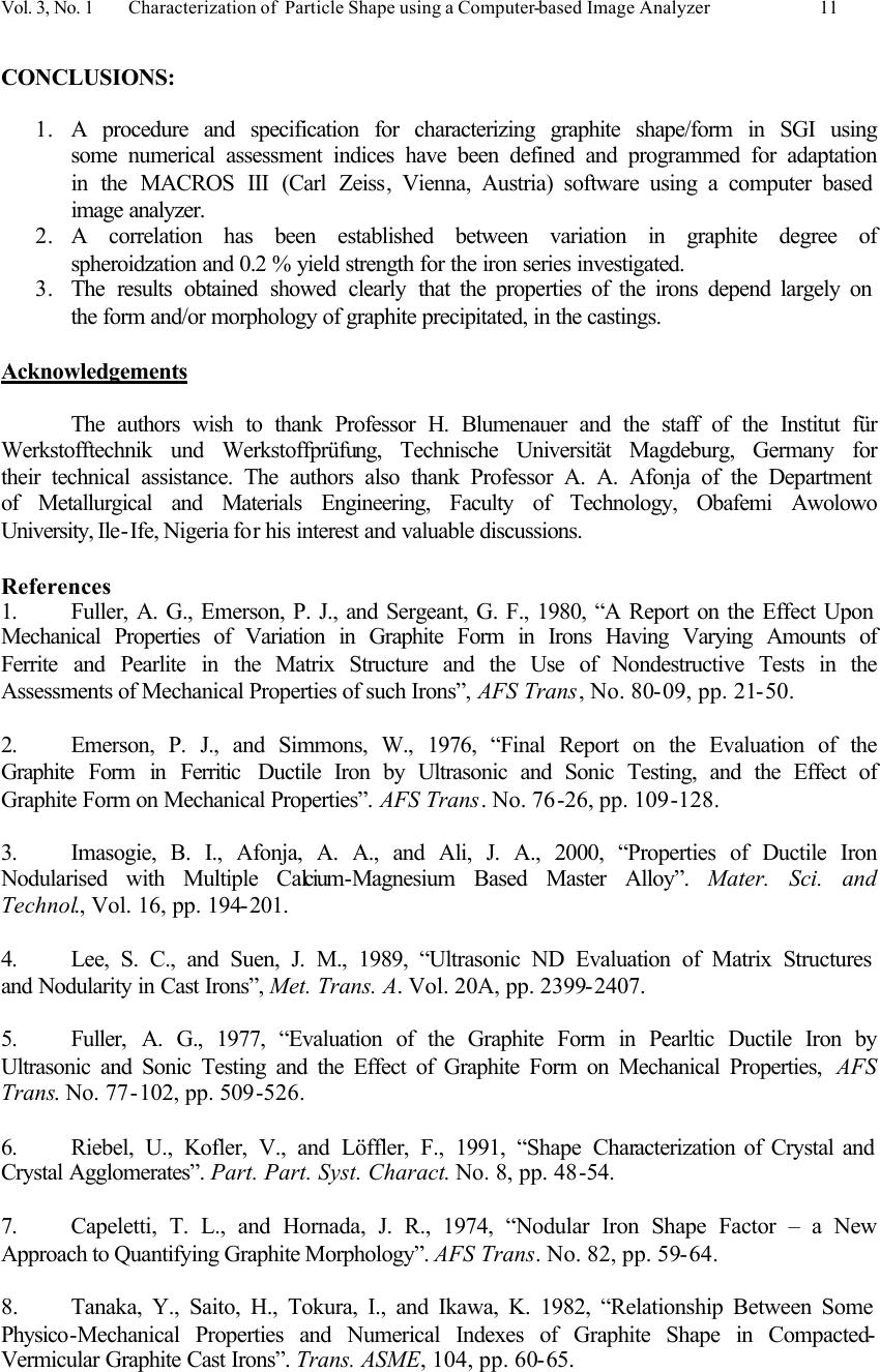 Vol. 3, No. 1 Characterization of Particle Shape using a Computer-based Image Analyzer 11 CONCLUSIONS: 1. A procedure and specification for characterizing graphite shape/form in SGI using some numerical assessment indices have been defined and programmed for adaptation in the MACROS III (Carl Zeiss, Vienna, Austria) software using a computer based image analyzer. 2. A correlation has been established between variation in graphite degree of spheroidzation and 0.2 % yield strength for the iron series investigated. 3. The results obtained showed clearly that the properties of the irons depend largely on the form and/or morphology of graphite precipitated, in the castings. Acknowledgements The authors wish to thank Professor H. Blumenauer and the staff of the Institut für Werkstofftechnik und Werkstoffprüfung, Technische Universität Magdeburg, Germany for their technical assistance. The authors also thank Professor A. A. Afonja of the Department of Metallurgical and Materials Engineering, Faculty of Technology, Obafemi Awolowo University, Ile-Ife, Nigeria for his interest and valuable discussions. References 1. Fuller, A. G., Emerson, P. J., and Sergeant, G. F., 1980, “A Report on the Effect Upon Mechanical Properties of Variation in Graphite Form in Irons Having Varying Amounts of Ferrite and Pearlite in the Matrix Structure and the Use of Nondestructive Tests in the Assessments of Mechanical Properties of such Irons”, AFS Trans, No. 80-09, pp. 21-50. 2. Emerson, P. J., and Simmons, W., 1976, “Final Report on the Evaluation of the Graphite Form in Ferritic Ductile Iron by Ultrasonic and Sonic Testing, and the Effect of Graphite Form on Mechanical Properties”. AFS Trans. No. 76-26, pp. 109-128. 3. Imasogie, B. I., Afonja, A. A., and Ali, J. A., 2000, “Properties of Ductile Iron Nodularised with Multiple Calcium-Magnesium Based Master Alloy”. Mater. Sci. and Technol., Vol. 16, pp. 194-201. 4. Lee, S. C., and Suen, J. M., 1989, “Ultrasonic ND Evaluation of Matrix Structures and Nodularity in Cast Irons”, Met. Trans. A. Vol. 20A, pp. 2399-2407. 5. Fuller, A. G., 1977, “Evaluation of the Graphite Form in Pearltic Ductile Iron by Ultrasonic and Sonic Testing and the Effect of Graphite Form on Mechanical Properties, AFS Trans. No. 77-102, pp. 509-526. 6. Riebel, U., Kofler, V., and Löffler, F., 1991, “Shape Characterization of Crystal and Crystal Agglomerates”. Part. Part. Syst. Charact. No. 8, pp. 48-54. 7. Capeletti, T. L., and Hornada, J. R., 1974, “Nodular Iron Shape Factor – a New Approach to Quantifying Graphite Morphology”. AFS Trans. No. 82, pp. 59-64. 8. Tanaka, Y., Saito, H., Tokura, I., and Ikawa, K. 1982, “Relationship Between Some Physico-Mechanical Properties and Numerical Indexes of Graphite Shape in Compacted- Vermicular Graphite Cast Irons”. Trans. ASME, 104, pp. 60-65.  12 B. I. Imasogie and U. Wendz Vol. 3, No.1 9. Underwood, E. E., Grebetz, J. C., and Koos, R. A., 1982, “Statistical Study of Graphite and Pearlite in Nodular Cast Iron”. Prakt. Metallogr. 19 (6), pp. 347-355 10. Machalikova, J., Skocovsky, P., Suchanek, V., and Sykora, P., 1991, “Quantitative Evaluation of Graphite Shape in Cast Iron”. Metallic Materials. 29 (3), pp. 174-180. 11. Ledbetter, H., and Datta, S., 1992, “Cast Iron Elastic Constants: Effect of Graphite Aspect Ratio”. Z. Metallkd. 83, 3, pp. 195-198. 12. Pundale, S. H., Rogers, R. J., and Nadkarni, G. R., 2000, “Finite Element Modelling of Elastic Modulus in Ductile Irons: Effect of Graphite Morphology”. AFS Trans. 98-102, pp. 99-105. 13. Li, J., Lu, L., and Lai, M. O., 2000, “Quantitative Analysis of the Irregularity of Graphite Nodules in Cast Iron”. Materials Characterization. 45, pp. 83-88. 14. Li, J., Lu, L., Su, Y., and Lai, M. O., 1999, “Fractal-based Description for Three- dimensional Surface of Materials”. J. Appl. Phys. 86, pp. 2526-2532. 15. Milman, V. Y., Stelmashenko, N. A., and Blumenfeld, R., 1994. “Fracture Surfaces: a Critical Review of Fractal Studies and a Novel Morphological Analysis of Scanning Tunneling Microscopy Measurements”. Prog. Mater. Sci, 38, pp. 425-474. 16. Imasogie, B. I., 2003, “Optimum Ca-CaC 2 -Mg Masteralloy Concentration Requirements in Graphite Nodularising Treatment of Cast Iron”. Materials Engineering. Vol. 14, No. 1, pp. 77-86. 17. Weichert, R., 1989, “Charakterisierung von Partikelkonturen Mittels Fraktalen und Komplexer Fourieranalyse”. Prepr. 4. Europ. Symp. Particle Characterization. Nürnberg, 19- 21 April, 1989, Vol. 1, pp. 409-420. 18. Clark, N. N., Diamond, H., Gelles, G., Bocoum, B., and Meloy, T. P., 1987, “Polygonal Harmonies of Silhouettes: Shape Analysis”. Part. Charact. 4, pp. 38-43. 19. Imasogie, B. I., 2003, “Microstructural Features and Mechanical Properties of Compacted Graphite Iron Treated with Calcium-Magnesium Based Masteralloy”. Journal of Materials Engineering and Performance, 12 (3), pp. 239-243. 20. Tsutsumi, N., and Imamura, M., 1978, “Proposal of the Classification of Spheroidal Graphite Form in Spheroidal Graphite Cast Iron”. Rept. Castings Res. Lab. Waseda University, No. 29, pp. 15-23. 21. Tsutsumi, N., and Imamura, M., and Sakuma, Y., 1979, “Analysis of the Fading Phenomena of Spheroidal Graphite in Magnesium Treated Iron Melt with Image Analyzing Computer”. Rept. Castings Res. Lab. Waseda University, No. 30, pp. 40-53. |

