Paper Menu >>
Journal Menu >>
 Journal of Minerals & Materials Characterization & Engineering, Vol. 2, No.1, pp43-51, 2003 http://www.jmmce.org, printed in the USA. All rights reserved 43 IRON ORE BENEFICIATION WITH PACKED COLUMN JIG D.C. Yang1, P. Bozzato1, G. Ferrara2 1 Mineral Technologies International, Inc., Morgantown, West Virginia, USA 2 DICAMP, University of Trieste, Trieste, Italy This paper presents several iron ore applications of the Packed Column Jig, a revolutionary and economical gravity separator of fine particulate materials, which can also be used for classification or desliming. The paper also describes the influence of important operational variables as well as a new control system to automatically monitor the process. Circular flow develops in any virtual cell bordered by the packing plates. Repeated separation takes place in a series of parallel vertical countercurrent circuits composed of a myriad of jigging cells that allows formation of a desired density bed without channeling problems. This leads to highly efficient separation with high throughput capacity and also permits linear scale -up by jig volume. Since no chemicals are used, the process is environmentally friendly. Due to the simplicity of the equipment and the circuit, per ton costs are substantially lower than conventional treatments. A typical product is a superconcentrate of 71.4% Fe and 1.5% SiO2 at over 93% iron recovery from a preconcentrate of 67.7% Fe and 5.6% SiO2. Keywords: iron ore, gravity separation, fine particles, packed column jig. Introduction During the last few decades, low-grade finely disseminated iron ore deposits have become the main sources of raw iron material in many countries. New technologies must be developed that achieve sharp separation at high throughput capacity, especially when treating very fine materials. These technologies must also maintain or improve current standards in more economic and environmentally attractive ways. Magnetic separation and flotation are the most widely accepted technologies for upgrading fine iron ore particles, but both processes result in iron concentrates with high amounts of very fine and/or interlocked silica particles. Gravity separation is a common process used in iron industry, but the separation efficiency becomes unacceptable with finely disseminated materials (<45 microns). In recent years, several advanced technologies have been developed to improve the separation of finer materials. Sharper separation is possible under dynamic conditions and/or in multistage processes. Dynamic separators can achieve sharp separation, but they are usually complex and expensive to maintain because of moving parts. Also, scale-up possibilities have not been completely proven (Sandvik and Rein, 1997). Multistage processes are energy intensive and difficult to operate and control. 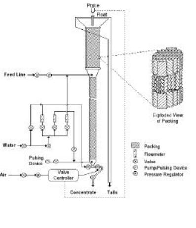 44 D.C. Yang, P. Bozzato, and G. Ferrara Vol. 2. No.1 Being single stage separators, packed columns (Yang, 1996) can replace multistage processes in flotation and gravity separation; further development into many other applications is foreseeable. For example, packing material is used for generating microbubbles in flotation and the packed device is also used as a Lamella thickener. Packed Column Jig (PCJ) is a gravity separator and operates like a teetered bed separator (Nicol, 1998), but the internal packing and a pulsating water flow allows higher throughput capacity and sharper separation. Packing also limits the turbulence and vorticity that takes place in each cell, thus avoiding short-circuiting of coarser particles, and leads to successful operation with fine particles extending the size range down to a few microns in diameter. PCJ does not require reagents to operate, has a higher capacity per unit cell volume than its competitors, gives sharp separation between iron ores and silica or other impurities, and is easily scaled up. Process description As shown in Figure 1, PCJ is a column filled with packing plates which are corrugated diagonally and set in an alternating configuration. The packing plates create a myriad of small cells in the column. A stream of mixed particles is fed through an inlet located near the top of the column. The feed point depends on the feed characteristics and concentrate grade target. A steady state water flow enters the bottom of the column and a pulsating flow is also superimposed to create a jigging action that maintains all particles in suspension limiting stagnation problems. Initially, light and fine particles move to the top while heavy and coarse particles move downward based on settling velocities. A density gradient is formed inside the column, high density at the bottom and low density at the top, and each of the product streams is discharged from the designated outlet. By changing operational conditions, light-coarse and heavy-fine particles are separated either on a size or density basis. A stronger density gradient means that particles tend to separate on density criteria. Jigging frequency is set based on particle size: finer particles require higher frequency. Two jigging frequencies can be superimposed to assure an effective particle separation while keeping particle dispersion. Packing plays many important roles in the jigging operation (Yang and Meloy, 1997), but the most important is its capability to scale up linearly. Packing allows an even and homogeneous distribution of feed material and water within two vertically stacked sections (See Figure 1 for the exploded view of three-layered Figure 1. Column jig schematic design. Vol. 2, No. 1 Iron Ore Beneficiation with Packed Column Jig 45 packing structure). Once the feed and up-flow water are evenly distributed, any virtual cells at the same height will perform a similar separation thus allowing linear scale-up of the column based on the cell volume or its cross-sectional area if the column height is similar. If virtual cells are identical in a 2-cm ID or 2-meter ID column, the probability that a particle is not misplaced is higher in a taller column because it will encounter more virtual cells during its passage through the separator. A pilot-scale column jig is currently being tested and has proven previous assertions. A column with the same packing has been used in the laboratory during the last five years without any noticeable change in performance. In some cases, a periodic cleaning, approximately once a year, eliminates incrustations on the packing when working in hostile conditions. Equipment A laboratory packed column jig measuring ¾-in (1.905 cm) ID by 2-ft (61.0 cm) tall was used in all the test work presented in this paper. The column can be divided into three regions: 1) the underflow discharge and packing section at the bottom which consists of 12 virtual cells of 1.3-cm in height each along the vertical axis, 2) the feed inlet section above the packing with 2.5 cm ID, and 3) the overflow discharge on top of the column measuring 2- in (5.08 cm) diameter at the discharge point. Its total volume was 600 ml. An extended feeding region is necessary because of the small dimensions of the laboratory unit. Otherwise, turbulence caused by diluted feed slurry would not allow a clear and stable mud line interface to form. In pilot or commercial units, packing is set inside an enlarged section above the feed point to avoid undesired turbulence. Feed material is mixed with water to a desired density in a tank. A peristaltic pump recirculates the slurry to limit segregation. A second pump provides the feed to the column from the recirculation line. The mud line is the interface between the light and heavy material inside the cone shaped overflow discharge. The heavy-small particle settlin g velocity is higher than the rising water velocity inside the cone where the interface is present, but the settling velocity is lower in the cylindrical section. A floating probe that detects the mud line controls the process. If the mud line rises above a certain level at which heavy valuable material could be lost with the tailings, the controller activates a pump or valve that adds water to the feed line to dilute the feed. Diluted feed decreases the density inside the cylindrical region and forces a migration of particles from the conical region at higher density downward lowering the mud line. In steady-state conditions, an on/off controller cycle of a few seconds assures that the equilibrium is established. In pilot and commercial units, the controlle r adjusts the underflow discharge pinch valve to maintain a constant distance between the mud line and the overflow discharge.  46 D.C. Yang, P. Bozzato, and G. Ferrara Vol. 2. No.1 Materials Extensive testing has been carried out using a magnetite concentrate from Mine A (Samples 1 and 2) and a magnetic taconite crude ore from Mine B (Sample 3), which contains 32.8% total Fe, but only 24.8% is magnetic Fe. This is important because the packed column jig can recover both magnetic and non-magnetic iron including magnetite and hematite while rejecting light undesired particles, including those interlocked with iron or other minerals. A crude hematite ore (Sample 4) was also tested to verify PCJ performance on coarser non-magnetic particles. Table I shows the fineness and the chemical analysis of the feed samples. The size distribution and individual grades of Sample 4 are presented in Table II. Table I : F ee d m at er ial c har ac ter is ti cs. Sample % <45 µm %Fe %SiO2 1 76.8 66.9 5.4 2 78.4 67.1 5.5 3 91.0 32.8 39.5 4 19.6 62.0 5.5 Table II: Size distribution and analyses of the non-magnetic feed. Size (µm) %Wt %Fe %SiO2 +100 4.67 58.17 8.61 -100+74 32.23 60.92 6.52 -74+45 43.52 63.69 4.39 -45 (sand) 13.15 66.58 2.30 -45 (slime) 6.43 49.54 12.57 Total 100 62.01 5.52 Experimental work The PCJ can achieve a desired separation through adjustment of a few operational variables listed below. • Rising velocity of water which separates particles based on their settling velocity • Frequency and amplitude of the superimposed jig action • Percent solids of the feed • Flowrate of the feed • Dilution of feed slurry for control purposes • Distance of the mud line from overflow discharge Figure 2: Flowsheet for processing non-magnetic iron ore. Iron Ore Sample 4 % Fe % SiO2 % Fe Rec % Wt Yang Jig 1 Tail 1Conc 1 61.25 6.17 100.00 100.00 68.05 1.28 62.45 56.21 52.52 11.89 37.55 43.79 49.54 12.57 8.32 10.2934.24 28.74 4.90 8.76 Screen 57.09 10.81 32.65 35.03 -74 micron+74 micron Yang Jig 2 Tail 2Conc 2 ScreenScreen 51.14 12.41 7.30 8.74 65.20 2.96 17.03 16.00 -45 m i cr on+45 micr o n-45 micron+45 micron 66.40 2.29 3.47 3.2064.90 3.12 13.56 12.8053.40 10.32 6.56 7.5237.20 25.36 0.74 1.22 Slimes 60.23 6.21 24.33 24.74  Vol. 2, No. 1 Iron Ore Beneficiation with Packed Column Jig 47 All of these variables have been recorded, and the influence of the variables on processing efficiency has been analyzed. To study feed particle size and liberation influence on packed column jig separation, Samples 1 and 2 were first tested as received. Microscopic observation showed that coarser particles contain more impurities. Therefore, the samples were comminuted to 89.7% <45 microns (Sample 2). Similarly, Sample 3 was tested as received and the concentrate was collected and reground to 98% <45 microns before second stage jigging. Because Sample 4 was coarser, a different flowsheet was adopted by adding a sizing step to obtain good separation at reasonable recovery (see Figure 2). A grade analysis showed that the >45 micron fraction contained 9.9% SiO2 while the finer fraction contained only 4.6% SiO2. In order to obtain a higher quality product a concentrate from the first-stage packed column jig test run was reground to 96.8% <45 microns and reprocessed in the second-stage jig (Sample 2). In order to compare the results, the first stage jig concentrate from Sample 1 was collected and ground to a 92.6% <45 microns size and a fresh sample was also ground to approximately the same size (93.1% <45 microns) before retreatment. Results and discussion Sa m pl e s 1 a n d 2 f r om M in e A Table III shows results obtained with Samples 1 and 2 respectively. Sample 1 was also tested using a laboratory mechanical flotation cell with %Fe recovery always below 90%, even if concentrate silica content was about 3% with or without size reduction of the feed sample. Table III: Results of packed column jigging on US taconite ores. Sample Product % <45µm Stage % Fe % SiO 2 %Fe Rec. 1 Conc. 76.8 1 68.8-68.6 3.3-3.8 96.3-98.0 92.6 2 70.8-70.1 2.0-2.1 92.2-95.3 93.1 1 70.4-69.8 2.3-2.4 95.2-96.9 Head 66.7-67.2 5.0-5.4 100.0 2 Conc. 78.4 1 68.9 3.4 97.6 89.7 1 70.6-70.4 2.1-2.2 97.2-97.4 96.8 2 71.4 1.5-1.6 96.0-96.1 Head 68.2-67.1 5.1-5.5 100.0 Some key variables that strongly affect PCJ separation have been analyzed in a previous work (Dai, 1999). A computer program was developed to simulate the process and the results are in good agreement with experimental tests. Other aspects, such as mud line distance from overflow discharge and throughput capacity, are analyzed in this work to better understand the process. A simple procedure can be developed in the near future for use in technical feasibility studies. Slurry density ranged between 5% and 10% to achieve a stable and easy control of the process and no difference in performance was noticed. Reducing feed particle size can produce progressively better concentrate quality. Figure 3 shows that after regrinding, lower silica content can be easily achieved.  48 D.C. Yang, P. Bozzato, and G. Ferrara Vol. 2. No.1 All tests presented in Figure 3 have been designed to optimize the separation performance by maximizing the concentrate grade and iron recovery or the process selectivity. For this reason most of the data points are close to each other. Based on the concentrate quality requirements, different approaches can be chosen. High quality concentrate (<2.0% SiO2) at high iron recovery can be achieved economically with a two- stage jig circuit with intermediate regrinding to at least 90% <45 microns. If a 2.3<%SiO2<2.5 concentrate meets the market requirements, a brief size reduction and a single stage jigging flowsheet assures simplicity and higher recovery than a more complicated and expensive two-stage jig. If higher silica levels are acceptable, a single stage PCJ can produce a 3.3% to 3.9% SiO2 concentrate at high recovery and high throughput capacity. Varying the throughput capacity and mud line distance from the overflow discharge can control the silica content in the concentrate as shown in Figures 4 and 5. Mud line distance from the overflow discharge and throughput capacity are interrelated. Higher capacities require a deeper mud line; otherwise increased turbulence can cause a short- circuiting of heavy and fine particles to the overflow discharge. 1.5 2 2.5 3 3.5 4 00.5 11.5 2 Feedrate [TPH per m3 of cell volume] %Silica in concentrate I stage PCJ as is II stage PCJ after regr. I stage PCJ after regr. 60 65 70 75 80 85 90 95 100 01 23 45 6 % Silica in concentrate % Fe recovery Sample, Stage, %<45 micron 1 1 76.8 1 2 92.6 1 1 93.1 2 1 78.4 2 1 89.7 2 2 96.8 Denver Cell Flotation 1 1 76.8 1 1 80-90 1.5 2 2.5 3 3.5 4 11.2 1.4 1.61.822.2 2.4 Mud line distance from overflow discharge [cm] % Silica in concentrate I stage PCJ II stage PCJ Figure 3: Grade - reco very curves obtained with packed column jig for Samples 1 and 2. Figure 4: Influence of feedrate on concentrate quality for Sample 1. Figure 5: Influence of mud line distance from overflow discharge for PCJ tests on Sample 1.  Vol. 2, No. 1 Iron Ore Beneficiation with Packed Column Jig 49 Throughput capacity affects concentrate quality in both the first and second stage with and without regrinding, respectively. But, in both cases, a higher capacity can provide good separation. To increase throughput capacity feed solid content must be increased otherwise rising water above the feed point would transport heavy-fine particles to the overflow discharge. Figure 3 together with Figure 4 can be used for technical decisions. Figure 6 shows that the amount of silica in the concentrate is strongly dependent upon the feed particle size regardless of the particular flowsheet or process; both flotation and PCJ results stay on the same line. What can vary is the throughput capacity and iron recovery that can be achieved once the final concentrate is set. Particle size reduction is not only necessary to obtain high quality concentrate, but at the same time it improves separation sharpness in terms of the selectivity index (SI) as can be seen in Figure 7. Figure 6: Relat ionsh ip bet ween feed p artic le siz e and impur ities in th e con centr ate. Figure 7: Re la tio nsh ip bet wee n f eed pa rti cle s ize a nd se para tion perfo rmanc e. Selectivity index = (%Fe recovery x Tails %Silica/Concentrate %Silica)½ 0 0.5 1 1.5 2 2.5 3 3.5 4 4.5 70 7580 85 90 95 100 % Finer than 45 microns % Silica in concentrate Sample 2 Sample 1 Flotation Sample 1 0 10 20 30 40 50 60 70 7580 85 90 95 100 % Finer than 45 microns Selectivity index Sample 2 Sample 1 Flotation Sample 1 50 D.C. Yang, P. Bozzato, and G. Ferrara Vol. 2. No.1 Sample 3 from Mine B The results obtained with Sample 3 indicate that a crude ore can be processed with two PCJ stages with regrind of the intermediate product, resulting in high recovery of magnetic and non-magnetic iron concentrate with low silica content. This efficient and simplified processing circuit can replace the existing flowsheets commonly used at many iron ore plants in North America involving multiple magnetic separation and flotation. First stage tests were conducted to maximize iron recovery while the second stage was designed to reduce concentrate silica content to 2 to 3% SiO2. If total iron is considered, economical advantages are enormous. For example, a two-stage PCJ can recover 77.3% of total iron in a concentrate containing 2.7% silica. While a typical plant production requires multistage of magnetic separation and flotation with stepped grind to accomplish, recovering 78.3% total iron at 5.7% silica content. Sample 4 from Mine C This sample is a crude non-magnetic iron ore (mostly hematite). To concentrate this sample that has a wider size distribution (see Table II), a different approach was designed to maximize recovery at low concentrate silica content. The first stage produces a final concentrate of coarser heavy particles while the tailings are processed in a second stage after removing coarse light particles. The same approach was tested to recover iron from a tailing pond feed and good results were achieved (50% Fe recovery at 4.5% SiO2 in concentrate from a <0.5 mm feed at 46% SiO2). This is important because the flowsheet can be applied to recover large amounts of non-magnetic iron disposed in dumpsites or tailing stockpiles over the years when no economical processes are available. These resources are cheap and abundant, and they do not need any additional crushing and grinding treatments. As shown in Figure 2, separation during the first stage is sharper. This is not surprising because finer particles positively interact with coarser particles to reduce pulp viscosity and increase the pulp density acting like a finely disseminated heavy medium. Another reason is that l than the original feed. During the second stage, the coarser fraction is poorer in iron and a more difficult separation is expected. Also, throughput capacity was much higher than before because feed particles have a much higher settling velocity. Conclusions The new Packed Column Jig separator and its control system have been presented and analyzed in detail. The following conclusions can be drawn from this work: 1. In finely ground iron ores, the packed column jig yields significantly higher grades and recoveries than do conventional flotation or magnetic separations; silica levels to less than 2% are economically achievable. 2. A two-stage packed column jig circuit with regrind to reduce concentrate size can produce higher quality concentrate at much higher iron recovery than present practices. Vol. 2, No. 1 Iron Ore Beneficiation with Packed Column Jig 51 This is due to its capability to recover non-magnetic iron and its unique design, which prevents misplacement of particles during separation. 3. Because no chemicals are used in the process, the column jig is environmentally friendly. Due to the simplicity of the equipment and the circuit, per ton costs are substantially lower than conventional treatments. 4. Wider feed particle size distributions can be effectively processed using a two-stage packed column jig circuit with screening of the intermediate product, if there are few interlocked particles. References Dai, Q., 1999. Simulation of Packed Column Jigging. Master’s Thesis, West Virginia University, Morgantown, West Virginia. Sandvik, K. and Rein, A., 1997. Gravity separation of bulk products in centrifugal fields. XX International Mineral Processing Congress. GMDB, Clausthal-Zellerfeld, pp. 599-610. Nicol, S., 1998. A case study in the implementation of novel technology: teetered bed separators. The Australian Coal Review, http://www.syd.dcet.csiro.au/acr6b.html. Yang, D.C., 1996. Device and process for gravitational separation of solid particles. US Patent No. 5,507,393, April 16. Yang, D.C., 1991. Technical advantages of packed flotation columns. Proceedings of Column ’91. Denison’s Quick Print & Copy House, Kitchener, Ontario, pp. 631-643. Yang, D.C. and Meloy, T.P., 1997. Gravity Separation of Minus 500 Mesh Particles. Presented at SME Annual Meeting, Denver, Colorado. |