Paper Menu >>
Journal Menu >>
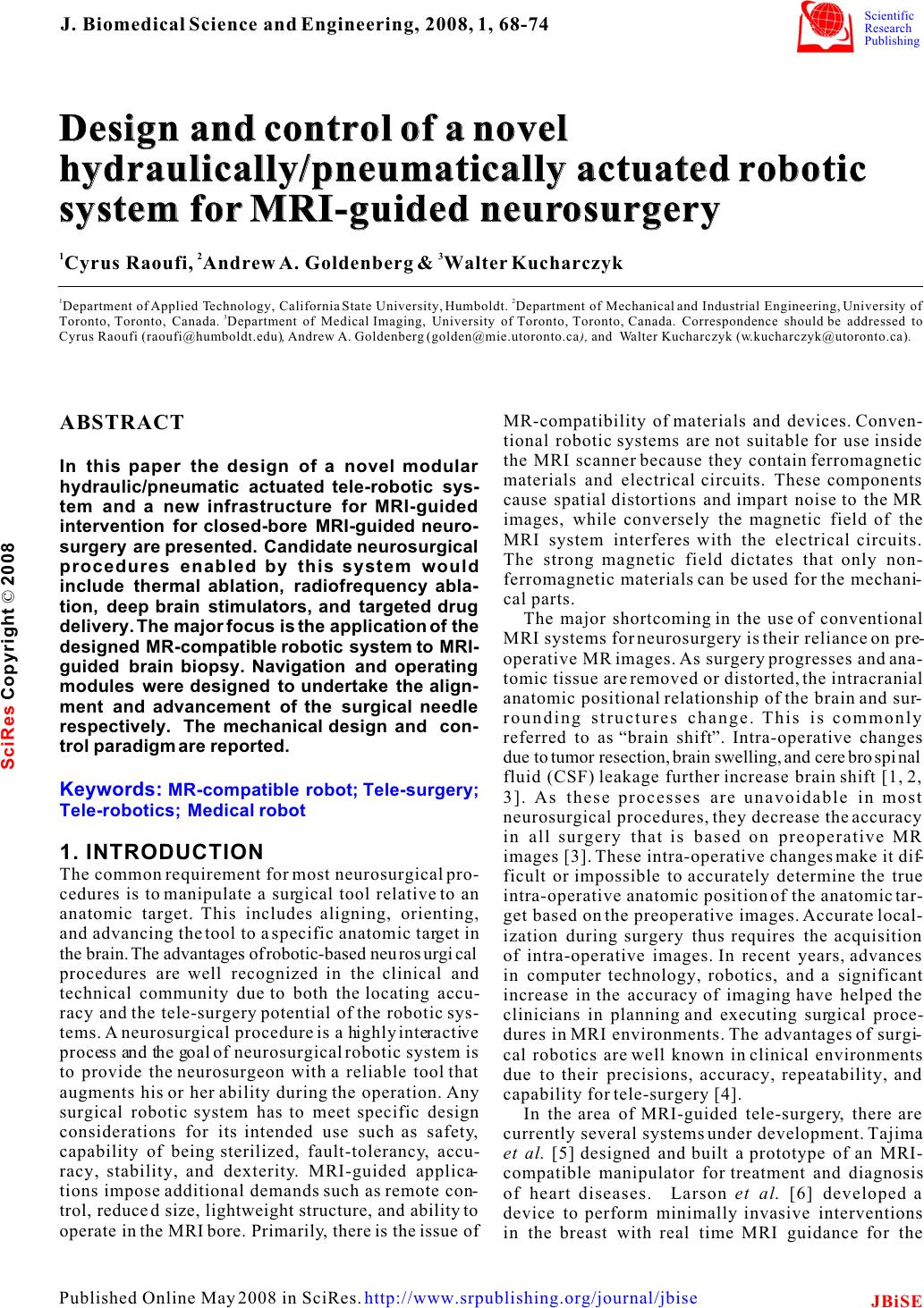 Design and control of a novel hydraulically/pneumatically actuated robotic system for MRI-guided neurosurgery Design and control of a novel hydraulically/pneumatically actuated robotic system for MRI-guided neurosurgery 12 3 Cyrus Raoufi, Andrew A. Goldenberg Walter Kucharczyk 12 Department of Applied Technology, California State University, Humboldt. Department of Mechanical and Industrial Engineering, University of 3 Toronto, Toronto, Canada. Department of Medical Imaging, University of Toronto, Toronto, Canada. Correspondence should be addressed to Cyrus Raoufi (raoufi@humboldt.edu), Andrew A. Goldenberg (golden@mie.utoronto.ca), and Walter Kucharczyk (w.kucharczyk@utoronto.ca). & MR-compatibility of materials and devices. Conven- ABSTRACT tional robotic systems are not suitable for use inside the MRI scanner because they contain ferromagnetic In this paper the design of a novel modular materials and electrical circuits. These components hydraulic/pneumatic actuated tele-robotic sys-cause spatial distortions and impart noise to the MR tem and a new infrastructure for MRI-guided images, while conversely the magnetic field of the intervention for closed-bore MRI-guided neuro-MRI system interferes with the electrical circuits. surgery are presented. Candidate neurosurgical The strong magnetic field dictates that only non- procedures enabled by this system would ferromagnetic materials can be used for the mechani- include thermal ablation, radiofrequency abla-cal parts. tion, deep brain stimulators, and targeted drug The major shortcoming in the use of conventional delivery. The major focus is the application of the MRI systems for neurosurgery is their reliance on pre- designed MR-compatible robotic system to MRI-operative MR images. As surgery progresses and ana- guided brain biopsy. Navigation and operating tomic tissue are removed or distorted, the intracranial modules were designed to undertake the align-anatomic positional relationship of the brain and sur- ment and advancement of the surgical needle rounding structures change. This is commonly respectively. The mechanical design and con-referred to as “brain shift”. Intra-operative changes trol paradigm are reported. due to tumor resection, brain swelling, and cerebrospinal fluid (CSF) leakage further increase brain shift [1, 2, 3]. As these processes are unavoidable in most neurosurgical procedures, they decrease the accuracy in all surgery that is based on preoperative MR 1. INTRODUCTIONimages [3]. These intra-operative changes make it dif- The common requirement for most neurosurgical pro-ficult or impossible to accurately determine the true cedures is to manipulate a surgical tool relative to an intra-operative anatomic position of the anatomic tar- anatomic target. This includes aligning, orienting, get based on the preoperative images. Accurate local- and advancing the tool to a specific anatomic target in ization during surgery thus requires the acquisition the brain. The advantages of robotic-based neurosurgical of intra-operative images. In recent years, advances procedures are well recognized in the clinical and in computer technology, robotics, and a significant technical community due to both the locating accu-increase in the accuracy of imaging have helped the racy and the tele-surgery potential of the robotic sys-clinicians in planning and executing surgical proce- tems. A neurosurgical procedure is a highly interactive dures in MRI environments. The advantages of surgi- process and the goal of neurosurgical robotic system is cal robotics are well known in clinical environments to provide the neurosurgeon with a reliable tool that due to their precisions, accuracy, repeatability, and augments his or her ability during the operation. Any capability for tele-surgery [4]. surgical robotic system has to meet specific design In the area of MRI-guided tele-surgery, there are considerations for its intended use such as safety, currently several systems under development. Tajima capability of being sterilized, fault-tolerancy, accu-et al. [5] designed and built a prototype of an MRI- racy, stability, and dexterity. MRI-guided applica-compatible manipulator for treatment and diagnosis tions impose additional demands such as remote con-of heart diseases. Larson et al. [6] developed a trol, reduced size, lightweight structure, and ability to device to perform minimally invasive interventions operate in the MRI bore. Primarily, there is the issue of in the breast with real time MRI guidance for the Keywords: MR-compatible robot; Tele-surgery; Tele-robotics; Medical robot J. Biomedical Science and Engineering, 2008, 1, 68-74Scientific Research Publishing JBiSE Published Online May 2008 in SciRes. http://www.srpublishing.org/journal/jbise SciRes Copyright © 2008 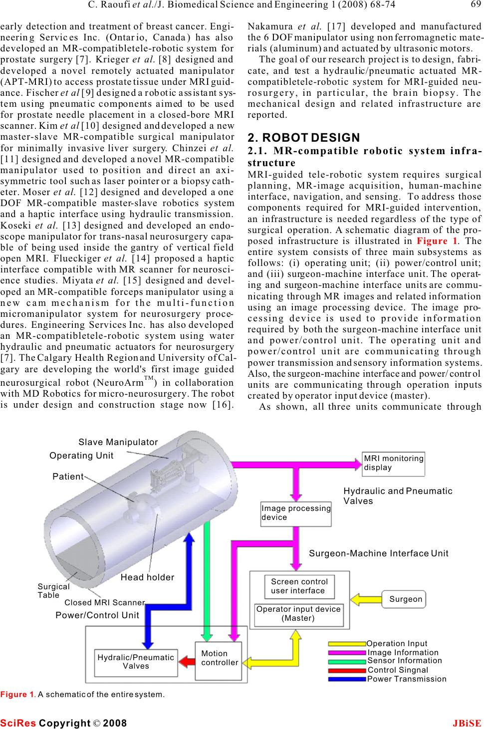 early detection and treatment of breast cancer. Engi-Nakamura et al. [17] developed and manufactured neering Services Inc. (Ontario, Canada) has also the 6 DOF manipulator using non ferromagnetic mate- developed an MR-compatibletele-robotic system for rials (aluminum) and actuated by ultrasonic motors. prostate surgery [7]. Krieger et al. [8] designed and The goal of our research project is to design, fabri- developed a novel remotely actuated manipulator cate, and test a hydraulic/pneumatic actuated MR- (APT-MRI) to access prostate tissue under MRI guid-compatibletele-robotic system for MRI-guided neu- ance. Fischer et al [9] designed a robotic assistant sys-rosurgery, in particular, the brain biopsy. The tem using pneumatic components aimed to be used mechanical design and related infrastructure are for prostate needle placement in a closed-bore MRI reported. scanner. Kim et al [10] designed and developed a new master-slave MR-compatible surgical manipulator 2. ROBOT DESIGN for minimally invasive liver surgery. Chinzei et al. 2.1. MR-compatible robotic system infra- [11] designed and developed a novel MR-compatible structure manipulator used to position and direct an axi-MRI-guided tele-robotic system requires surgical symmetric tool such as laser pointer or a biopsy cath-planning, MR-image acquisition, human-machine eter. Moser et al. [12] designed and developed a one interface, navigation, and sensing. To address those DOF MR-compatible master-slave robotics system components required for MRI-guided intervention, and a haptic interface using hydraulic transmission. an infrastructure is needed regardless of the type of Koseki et al. [13] designed and developed an endo-surgical operation. A schematic diagram of the pro- scope manipulator for trans-nasal neurosurgery capa-posed infrastructure is illustrated in . The ble of being used inside the gantry of vertical field entire system consists of three main subsystems as open MRI. Flueckiger et al. [14] proposed a haptic follows: (i) operating unit; (ii) power/control unit; interface compatible with MR scanner for neurosci-and (iii) surgeon-machine interface unit. The operat- ence studies. Miyata et al. [15] designed and devel-ing and surgeon-machine interface units are commu- oped an MR-compatible forceps manipulator using a nicating through MR images and related information new cam mechanism for the multi-function using an image processing device. The image pro- micromanipulator system for neurosurgery proce-cessing device is used to provide information dures. Engineering Services Inc. has also developed required by both the surgeon-machine interface unit an MR-compatibletele-robotic system using water and power/control unit. The operating unit and hydraulic and pneumatic actuators for neurosurgery power/control unit are communicating through [7]. The Calgary Health Region and University of Cal-power transmission and sensory information systems. gary are developing the world's first image guided Also, the surgeon-machine interface and power/control TM neurosurgical robot (NeuroArm) in collaboration units are communicating through operation inputs with MD Robotics for micro-neurosurgery. The robot created by operator input device (master). is under design and construction stage now [16]. As shown, all three units communicate through Figure 1 Figure 1. A schematic of the entire system. SciRes JBiSE Copyright © 2008 69 C. Raoufi et al./J. Biomedical Science and Engineering 1 (2008) 68-74 Operating Unit Power/Control Unit Surgeon-Machine Interface Unit Hydraulic and Pneumatic Valves Operation Input Image Information Sensor Information Control Singnal Power Transmission Surgeon MRI monitoring display Image processing device Screen control user interface Operator input device (Master) Motion controller Hydralic/Pneumatic Valves Patient Surgical Table Closed MRI Scanner Head holder Slave Manipulator 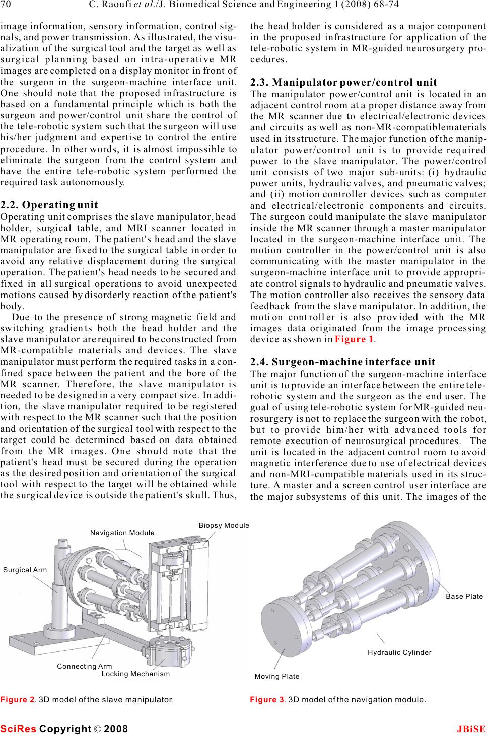 image information, sensory information, control sig-the head holder is considered as a major component nals, and power transmission. As illustrated, the visu-in the proposed infrastructure for application of the alization of the surgical tool and the target as well as tele-robotic system in MR-guided neurosurgery pro- surgical planning based on intra-operative MR cedures. images are completed on a display monitor in front of the surgeon in the surgeon-machine interface unit. 2.3. Manipulator power/control unit One should note that the proposed infrastructure is The manipulator power/control unit is located in an based on a fundamental principle which is both the adjacent control room at a proper distance away from surgeon and power/control unit share the control of the MR scanner due to electrical/electronic devices the tele-robotic system such that the surgeon will use and circuits as well as non-MR-compatiblematerials his/her judgment and expertise to control the entire used in its structure. The major function of the manip- procedure. In other words, it is almost impossible to ulator power/control unit is to provide required eliminate the surgeon from the control system and power to the slave manipulator. The power/control have the entire tele-robotic system performed the unit consists of two major sub-units: (i) hydraulic required task autonomously. power units, hydraulic valves, and pneumatic valves; and (ii) motion controller devices such as computer 2.2. Operating unitand electrical/electronic components and circuits. Operating unit comprises the slave manipulator, head The surgeon could manipulate the slave manipulator holder, surgical table, and MRI scanner located in inside the MR scanner through a master manipulator MR operating room. The patient's head and the slave located in the surgeon-machine interface unit. The manipulator are fixed to the surgical table in order to motion controller in the power/control unit is also avoid any relative displacement during the surgical communicating with the master manipulator in the operation. The patient's head needs to be secured and surgeon-machine interface unit to provide appropri- fixed in all surgical operations to avoid unexpected ate control signals to hydraulic and pneumatic valves. motions caused by disorderly reaction of the patient's The motion controller also receives the sensory data body. feedback from the slave manipulator. In addition, the Due to the presence of strong magnetic field and motion controller is also provided with the MR switching gradients both the head holder and the images data originated from the image processing slave manipulator are required to be constructed from device as shown in . MR-compatible materials and devices. The slave manipulator must perform the required tasks in a con-2.4. Surgeon-machine interface unit fined space between the patient and the bore of the The major function of the surgeon-machine interface MR scanner. Therefore, the slave manipulator is unit is to provide an interface between the entire tele- needed to be designed in a very compact size. In addi-robotic system and the surgeon as the end user. The tion, the slave manipulator required to be registered goal of using tele-robotic system for MR-guided neu- with respect to the MR scanner such that the position rosurgery is not to replace the surgeon with the robot, and orientation of the surgical tool with respect to the but to provide him/her with advanced tools for target could be determined based on data obtained remote execution of neurosurgical procedures. The from the MR images. One should note that the unit is located in the adjacent control room to avoid patient's head must be secured during the operation magnetic interference due to use of electrical devices as the desired position and orientation of the surgical and non-MRI-compatible materials used in its struc- tool with respect to the target will be obtained while ture. A master and a screen control user interface are the surgical device is outside the patient's skull. Thus, the major subsystems of this unit. The images of the Figure 1 Figure 2. 3D model of the slave manipulator.Figure 3. 3D model of the navigation module. SciRes JBiSE Copyright © 2008 70 C. Raoufi et al./J. Biomedical Science and Engineering 1 (2008) 68-74 Navigation Module Biopsy Module Connecting Arm Locking Mechanism Surgical Arm Base Plate Hydraulic Cylinder Moving Plate 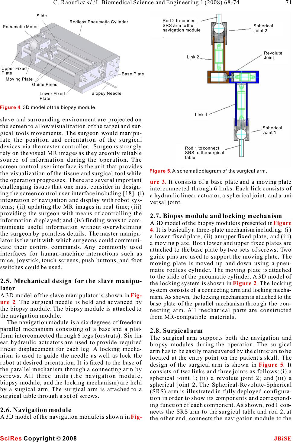 slave and surrounding environment are projected on the screen to allow visualization of the target and sur- gical tools movements. The surgeon would manipu- late the position and orientation of the surgical devices via the master controller. Surgeons strongly rely on the visual MR images as they are only reliable source of information during the operation. The screen control user interface is the unit that provides the visualization of the tissue and surgical tool while the operation progresses. There are several important It consists of a base plate and a moving plate challenging issues that one must consider in design-interconnected through 6 links. Each link consists of ing the screen control user interface including [18]: (i) a hydraulic linear actuator, a spherical joint, and a uni- integration of navigation and display with robot sys-versal joint. tems; (ii) updating the MR images in real time; (iii) providing the surgeon with means of controlling the 2.7. Biopsy module and locking mechanism information displayed; and (iv) finding ways to com-A 3D model of the biopsy module is presented in municate useful information without overwhelming It is basically a three-plate mechanism including: (i) the surgeon by pointless details. The master manipu-a lower fixed plate, (ii) anupper fixed plate, and (iii) lator is the unit with which surgeons could communi-a moving plate. Both lower and upper fixed plates are cate their control commands. Any commonly used attached to the base plate by two sets of screws. Two interfaces for human-machine interactions such as guide pins are used to support the moving plate. The mice, joystick, touch screens, push buttons, and foot moving plate is moved up and down using a pneu- switches could be used. matic rodless cylinder. The moving plate is attached to the slide of the pneumatic cylinder. A 3D model of 2.5. Mechanical design for the slave manipu-the locking system is shown in The locking lator system consists of a connecting arm and locking mecha- A 3D model of the slave manipulator is shown in nism. As shown, the locking mechanism is attached to the The surgical needle is held and advanced by base plate of the parallel mechanism through the con- the biopsy module. The biopsy module is attached to necting arm. All mechanical parts are constructed the navigation module.from MR-compatible materials. The navigation module is a six degrees of freedom parallel mechanism consisting of a base and a plat-2.8. Surgical arm form interconnected through 6 legs (or struts). Six lin-The surgical arm supports both the navigation and ear hydraulic actuators are used to provide required biopsy modules during the operation. The surgical linear displacement for each leg. A locking mecha-arm has to be easily maneuvered by the clinician to be nism is used to guide the needle as well as lock the located at the entry point on the patient's skull. The robot at desired orientation. It is fixed to the base of design of the surgical arm is shown in . It the parallel mechanism through a connecting arm by consists of two links and three joints as follows: (i) a screws. All three units (the navigation module, spherical joint 1; (ii) a revolute joint 2; and (iii) a biopsy module, and the locking mechanism) are held spherical joint 2. The Spherical-Revolute-Spherical by a surgical arm. The surgical arm is attached to a (SRS) arm is illustrated in fully deployed configura- surgical table through a set of screws.tion in order to show its components and correspond- ing function of each component. As shown, rod 1 con- 2.6. Navigation modulenects the SRS arm to the surgical table and rod 2, at A 3D model of the navigation module is shown in the other end, connects the navigation module to the ure 3. Figure 4. Figure 2. Fig- ure 2. Figure 5 Fig- Figure 4. 3D model of the biopsy module. SciRes JBiSECopyright © 2008 C. Raoufi et al./J. Biomedical Science and Engineering 1 (2008) 68-74 71 Figure 5. A schematic diagram of the surgical arm. Rod 2 to connect SRS arm to the navigation module Spherical Joint 2 Revolute Joint Link 2 Link 1 Spherical Joint 1 Rod 1 to connect SRS to the surgical table Pneumatic Motor Rodless Pneumatic Cylinder Slide Upper Fixed Plate Moving Plate Guide Pines Base Plate Lower Fixed Plate Biopsy Needle  operative images as visual feedback. When the nee- dle reaches the target, it is rotated by 180 degrees in order to cut the tissue specimen (tumor). Then the nee- dle is pulled out completing the operation. (6)Final stage. The MRI table is moved out the MRI bore. The slave manipulator and head holder are detached from the table and patient's skull respec- tively. 3.2. Robot control architecture As mentioned, the surgeon adjusts the orientation of the surgical tool (yaw and pitch angles) based on visual MR images through the master. The inverse kinematics of the navigation module is used to obtain the desired length of each strut related to the desired position and orientation of the needle biopsy. The hydraulic/pneumatic circuit of the system and overall control system are shown in and respectively. Six MR-compatible hydraulic cyl- inders are equipped with six fiber optic encoders to SRS arm.feedback the actual length of each strut. Using inverse kinematic of the navigation module, the desired length of each strut of the navigation module 3. ROBOT CONTROLis determined. A PID controller provides a control sig- 3.1. Needle alignment nal that drives a hydraulic proportional valve in each An entry point, a surgical tool and a target are servo control loop. The hydraulic valve controls the depicted in . Required motions to align and length of the strut by regulating the flow from/to each advance the surgical tool with respect to the target hydraulic actuator. In addition, a pneumatic valve are also shown. The surgical tool is rotated about the (V7) is used to control the tip position of the biopsy burr-hole by Yaw and Pitch angles. This point is also needle. The semi-rotary pneumatic motor is also actu- called the pivot point. The conventional surgical tool ated by an on/off pneumatic valve (V8). placement at an entry point includes the following A block diagram of the control algorithm used in three tasks: (i) move the needle tip to the entry point the controller is shown in . The inputs are using 3 DOFs; (ii) orient the needle by pivoting six feedback displacement signals from the slave side around the entry point using 2DOF (Yaw and Pitch (LA1, LA2, LA3, LA4, LA5, and LA6), two signals angles); and (iii) insert the needle into the body using form master side including desired Yaw and Pitch 1 DOF (translation along a straight trajectory). Using angels, and desired length of each strut (LD1, LD2, the proposed tele-robotic system shown in , LD3, LD4, LD5, and LD6). The outputs are control the brain biopsy procedure would be carried out as fol-signals (S1, S2, S3, S4, S5, and S6) to control the pro- lows: portional valves. (1)Preoperative imaging stage. The patient is A PC-based supervisory controller is designed to placed inside the MRI scanner and preoperative control entire system as illustrated in . The images are obtained. trajectory of each joint is calculated based on the (2)Surgical planning stage. Based on the pre-inverse kinematics in a PC-based supervisory con- operative images, an entry point is determined and troller and fed to each joint controller RS485 Bus. As the incision is made by a surgeon. shown in , six optical encoders are used to (3)Pre-alignment stage. The slave manipulator is feedback the position signals to six microprocessors. attached to the surgical table, and the navigation mod-Each actuator has individual microprocessor to con- ule and biopsy needle are manually located at the trol its proportional valve. entry point. Although this stage doesn't require high accuracy in positioning, the slave has to be locked 4. CONCLUSION AND FUTURE WORK such that the surgical tool is positioned at the entry We have designed an MR-compatible tele-robotic sys- point. Accurate alignment with respect to target will tem that can be used for orientation and advancement be done in the next stage; of a biopsy needle on the brain biopsy procedure. The (4)Real time navigation stage. The patient is moved robot has been designed such that it will perform into the bore of MRI scanner. The navigation module desired tasks inside MR scanner GE Signa 1.5T. To is maneuvered remotely in order to align the surgical date, design and analysis of the entire system have tool with the desired direction based on intra-been completed. Material selection and the controller operative images. architecture and its component have been finalized. (5)Intra-operative operation stage. The operation A physical prototype of the slave manipulator is in is carried out by advancing the needle using intra-the process of being constructed. Current and future Figure 7Fig- ure 8 Figure 6 Figure 9 Figure 1 Figure 10 Figure 10 SciRes JBiSE Copyright © 2008 72 C. Raoufi et al./J. Biomedical Science and Engineering 1 (2008) 68-74 Figure 6. The target, entry point, and the needle. Burr Hole (Pivot point)Surgical ToolAxial Pitch/Yaw Roll Target  Figure 9. A schematic of overall control architecture. SciRes JBiSE Copyright © 2008 C. Raoufi et al./J. Biomedical Science and Engineering 1 (2008) 68-74 73 Figure 8. A schematic of overall control architecture. Figure 7. A schematic of hydraulic/pneumatic circuit. Copmuter or/and Panel Surgeon Input Master PC Based Controller FID CONTROLLER Inverse Kinematic Rodless Cylinder Semi-rotary pneumatic motor V8 V7 V6 V5 V4 V3 V2 V1 V1 V2 V3 V4 V5 V6 V7 V8 A6 A5 A4 A3 A2 A1 Hydranlic Unit Compressed Air Air Pre-preparation Unit Low magnetic fieldInside MR scanner Semi-rotary Motor Rodless Cylinder Desired Lenghts: LD1 LD2 LD3 LD4 LD5 LD6 Control Singnals: S1 S2 S3 S4 S5 S6 Trajectory Planing Inverse kinematic Master Desired trajectory: Yaw Angel Pitch Angel Actual Lenghts La1 La4 La2 La5 La3 La6 PID Controller Optical Encoders Proportional ValvesHydraulic Actuators  Manipulator for Image Guided Prostate Intervention. IEEE work includes the development of the slave manipu-Trans. On Biomedical Engineering 2005, 52(2):306-313. lator and performance of series of experimental tests [9]G.S. Fischer, I. Iordachita, S. P. DiMaio & G. Fichtiger. Design inside the MR scanner using the first physical proto-of a Robot for Transperineal Prostate Needle Placement in MRI type. scanner. IEEE International Conference on Mechatronics 2006, page 6. [10]K. Daeyoung et al. A New, Compact MR-Compatible Surgical Manipulator for Minimally Invasive Liver Surgery. MICCAI 2002, pages 99-106. [11]K. Chinzei & K. Miller. MR Guided Surgical Robot. Proc. ACKNOWLEDGEMENTS 2001 Australian Conference on Robotics and Automation This work was partially supported by Natural Sciences and Engi-2001, Sydney. neering Research Council of Canada (NSERC), grant held by Pro-[12]R. Moser, R. Gassert, E. Burdet, L. Sache, H. Woodtli, J. Erni, fessor Andrew A. Goldenberg and Ontario Research and Develop-W. Maeder & H. Bleuler. An MR-compatibleRobot Technol- ment Challenge Fund (ORDCF), grant held by Professor W. ogy. Proc. Of the IEEE, International Conference on Robotics Kucharczyk. The authors would like to thank Engineering Services & Automation 2003. Inc., Canada, and MRI department in Toronto General Hospital, [13]Y. Koseki, T. Washio, K. Chinzei & H. Iseki. Endoscope Canada, for providing help and equipment.Manipulator for Trans-nasal Neurosurgery, Optimized for and Compatible to Vertical Field Open MRI. Proc. of MICCAI 2002, pages 114-121. REFERENCE [14]M. Flueckiger, M. M. Bullo et al. FMRI compatible haptic [1]R. D. Howe, & Y. Matsuoka. Robotics for Surgery. Annual interface actuated with traveling wave ultrasonic motor. IAS Review of Biomedical Engineering 1999, 1:211-240.Annual Meeting (IEEE Industry Applications Society) 2005, [2]J. Kettenbach, D. F. Kacher, S.K. Koskinen, S. Silverman, A. 3:2075-2082. Nabavi, D. Geringt, C. Tempany, R. B. Schwartz, R.Kikinis, P. [15]N. Miyata , E. Kobayashi, D. Kim, K. Masamue et al. Micro- K. Black & F.A. Jolesz. Interventional and Intra-operative Mag-grasping Forceps Manipulator for MR-Guided Neurosurgery. netic Resonance Imaging. Annual Review Biomedical Engi-MICCAI 2002, pages 107-113. neering 2000, 2:661-90.[16]Calgary HealthTrust, www.cbi.ucalgary.ca/CHT, 2004. [3]A. Nabavi, D. F. Kacher, D. T. Gering et al. Neurosurgical pro-[17]R. Nakamura, K. Masamune, Y. Nishikawa, E. Koboayashi, I. cedure in 0.5 Tesla, open-configuration intraoperative MRI: Sakuma,T. Dohi, H. Iseki & K. Takakura. Development of a planning, visualization, and navigation. Automedia 2001, 00:1-sterilizable MRI-compatible manipulator for stereotactic neu- 35. rosurgery. Proc. Of Computer Assisted Radio Surgery [4]K. Chinzei, N. Hata, F.A. Jolesz, & R. Kikinis, Medical Image (CAR'99) 1999. Computing and Computer-Assisted Intervention - MICCAI [18]R. Taylor & D. Stoianovici. Medical Robotics in Computer- 2000. Third International Conference Proceedings 2000, pages Integrated Surgery. IEEE Transaction on Robotics and Auto- 921-30. mation 2003, 32(5):765-781. [5]F. Tajima, K. Kishi, K. Nishizawa, K. Kan, Y. Nemoto, H. Takeda et al. Development of MR-compatibleSurgical Manipu- lator toward a Unified Support System for Diagnosis and Treat- ment of Heart Disease. Proc .of MICCA O2 2002, pages 83-90. [6]B. Larson, N. Tsekos & A. g. Erdman. A Robotic Device for Minimally Invasive Breast Intervention with Real-Time MRI Guidance. Proc. Of the Third IEEE Symposium on Bioinformatics and Bioengineering 2003. [7]Engineering Services Inc., http://www.esit.com, Internal report. [8]A. Krieger, R. Susil, C. Menard, J. Coleman, G. Fichtinger, E. Atalar, & L. Whitcomb. Design of a Novel MRI Compatible SciRes JBiSE Copyright © 2008 74 C. Raoufi et al./J. Biomedical Science and Engineering 1 (2008) 68-74 Figure 10. Supervisory control configuration. Supervisory Controller PC Rs485 Bus Joint Control: Microprocessor(6) Proportional Valve(V6) Optical Sensor(S6) Joint 6 Joint Control: Microprocessor(2) Proportional Valve(V2) Optical Sensor(S2) Joint 2 Joint 1 Joint Control: Microprocessor(1) Proportional Valve(V1) Optical Sensor(S1) |