Circuits and Systems
Vol.07 No.08(2016), Article ID:67243,10 pages
10.4236/cs.2016.78020
An Investigation of Power Converters Fed BLDC Motor for Adjustable Speed
Subramaniam Kaliappan1, Dr. Ramachandran Rajeswari2
1Department of Electrical and Electronics Engineering, Kumaraguru College of Technology, Coimbatore, India
2Department of Electrical and Electronics Engineering, Government College of Technology, Coimbatore, India

Copyright © 2016 by authors and Scientific Research Publishing Inc.
This work is licensed under the Creative Commons Attribution International License (CC BY).
http://creativecommons.org/licenses/by/4.0/


Received 7 April 2016; accepted 22 April 2016; published 9 June 2016
ABSTRACT
This paper reports the converter topologies which are employed for better Power Factor Correction at the input side. The Power Factor Correction is an important factor when considering the Power Quality. Based on the converter topologies, the Bridgeless converters are preferred in order to reduce the number of switching devices, losses associated with it and improve the Power Quality further more. This paper investigates about the Power Factor performances and conduction losses of the Bridgeless Power Factor Corrector Converters which see through the benefits and limitations by analyzing the Bridgeless Buck-Boost Converter, Bridgeless SEPIC converter and Bridgeless CUK converter. The resultant voltage is fed to the BLDC motor which is rapidly replacing the Induction motor for its better operating characteristics. These strategies are being analyzed using the MATLAB/Simulink software and the results are verified through the experimental analysis. The converter choice is preferred through the performance characteristics and Power Factor Correction at the supply. The Power Factor obtained should be within the acceptable limits under IEC 61000-3-2 standards.
Keywords:
BLDC Motor, Power Factor Correction, Power Quality, PFC Converters

1. Introduction
There are two factors that provide the quantitative measure for the quality of power supply in an electrical network. They are the Power Factor and Total Harmonic Distortion (THD). The Power Factor (PF) of the system predominantly decides the amount of useful power to be consumed by an electric network [1] . The reward of Power Factor Correction includes less energy and distortion losses, reduced losses in the system at the time of distribution, improved voltage regulation and can supply the power demand. This paper deals with the Power Factor Correction thereby improving the Power Quality at ac mains. The input bridge rectifier in the conventional Power Factor Corrector converters reduces the efficiency of the converter. In order to reduce the losses associated with the rectifier, the rapidly developing power electronic strategies are employed [2] [3] . Some of the limitations are Stresses across the switch, since a single switch for both the period of conduction, conduction losses, etc. The Bridgeless Buck-Boost converter has two semiconductor switches for both the current direction. Each switch is turned on for the each half cycle. The first switch conducts for the positive half cycle whose PWM signals for both the switches are same [4] - [7] . This converter has better performance than the other two PFC converters. Thereby the efficiency is also increased which results in the unity power factor at the supply which is under the Power Quality standards. The output voltage from the inverter is fed to the BLDC motor, which has obtained its place for its noiseless operation, less maintenance and greater flux density. The motor is electronically commutated using the power electronic switches [8] [9] . Based on the drawbacks of the conventional converters the Bridgeless converters are proposed to overcome all these criteria. This paper investigates the Bridgeless Cuk, Bridgeless SEPIC, Bridgeless Buck-Boost converters. These converters individually perform well with improved power factor but have some merits and demerits when comparing each other converters [10] - [12] . The conduction losses and the thermal stress across the switch get reduced and thereby increase the efficiency of the converter. It requires a additional gate drive transformer, similarly the capacitance and inductance are also needed for further reduction in the stress across the switch. This is the drawback in this converter topology. The Bridgeless Cuk converter as stated above has the same advantages and further adds the zero current turn on and zero current turn off. This reduces the difficulty of the controller. The only drawback in PFC Cuk converter is floating switch and step up voltage more than 2. Hence achieving the Unity Power Factor through this converter is little difficult. The AC-DC Bridgeless SEPIC converter is employed with two switches which replaces the diodes in the input bridge rectifier. The absence of Diode Bridge Rectifier and each diode for each current flow path reduces the conduction losses and improves the efficiency of the converter. The Hall sensors are employed in order to locate the position of the rotor. The current to the motor is fed to the controller. The PIC controller is used for its good performance [13] [14] .
2. CUK Converter Fed BLDC Motor
Figure 1 shows the block diagram of CUK converter fed BLDC motor. The proposed PFC CUK converter based VSI fed BLDC motor has been designed and simulated in MATLAB/Simulink. This method of speed (N) control utilize the controlling the DC link voltage. The CUK converter produces less ripple current with less number of switching devices.
The estimated performance has been achieved for wider ranges of speed control and variation of supply voltage. The obtained Power Factor 0.85 and the current THD 3.09% are within the acceptable Power Quality limits of IEC 61000-3-2 is shown in Table 1. Still the stress across the switch can be further reduced and the performance can be improved.
3. Bridgeless Buck-Boost Converter Fed BLDC Motor
The Bridgeless Buck-Boost Converter fed BLDC motor is simulated in MATLAB/Simulink. The THD of supply
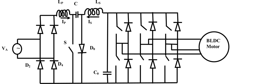
Figure 1. Block diagram of CUK converter fed BLDC motor.
current at ac mains with output power for the proposed scheme of the Bridgeless (BL) buck-boost converter fed BLDC motor drive is achieved within the IEC 61000-3-2 limits. The assessment is based on the control requirement and losses in the PFC converter and VSI-fed BLDC motor is shown in Figure 2.
The speed (N) remains constant even with the change in voltage. The attained current Total Harmonic Distortion (T.H.D) is 2.89% is shown in Table 2. The simulation results the Power Factor (PF) in 0.95 which is closer to the Unity Power factor, doesn’t cause Power Quality issues at ac mains.
4. Bridgeless SEPIC Converter Fed BLDC Motor
The Bridgeless SEPIC converter fed BLDC motor is simulated in MATLAB/Simulink. The THD of source current at ac mains with output power for the proposed scheme of the BL SEPIC Ripple Free converter fed BLDC motor drive is obtained within the IEC 61000-3-2 limits. The assessment is based on the control requirement and losses in the PFC converter and VSI-fed BLDC motor is shown in Figure 3. The speed remains constant even with the change in voltage. The attained current Total Harmonic Distortion (T.H.D) is 1.94% is shown in Table 3. The simulation gives the Power Factor in 0.99 which is closer to the Unity Power factor, doesn’t cause Power Quality issues at ac mains.
5. Block Diagram
Figure 4 shows the block diagram of proposed system. The speed of BLDC motor is directly relative to the DC

Table 1. Performance of PFC cuk converter-fed BLDC Motor drive under speed control.
Table 2. Performance of PFC BL buck-boost converter fed BLDC motor drive under speed control.
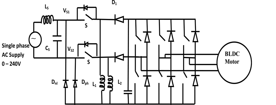
Figure 2. Block diagram of buck-boost converter fed BLDC motor.
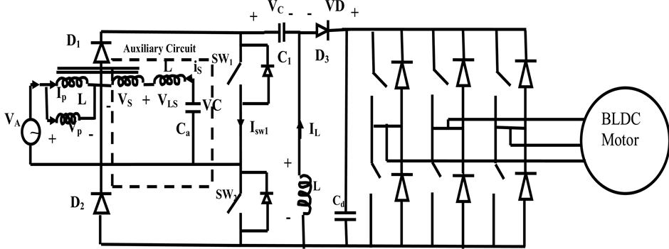
Figure 3. Block Diagram of proposed Bridgeless SEPIC converter fed BLDC motor.

Figure 4. Block diagram of proposed system.
Table 3. Performance of PFC BL SEPIC converter-fed BLDC motor drive under speed control.
link voltage. Pulse period is directly proportional to the rate of the POT input. When the rate of input is low, pulse will be thin and the converter output voltage is small. When the value of input is high, pulse will be thick and the converter output voltage is high. When the DC link voltage of the converter is varied the speed of the motor is varied without human intervention with high power factor. The motor utilizes the given DC power resourcefully. The controller generates 8 PWM pulses for the VSI and the converter.
PWM control fine-tunes the duty ratio of the BLDC motor. The average DC value of the signal can be varied by changing the duty cycle. The PWM pulse is used to activate the MOSFET switches of the voltage source inverter (VSI). The Hall Sensor is used to discover the rotor position of the motor. Based on this the VSI switches will be given with PWM pulses. For every position of the rotor, different MOSFET switches are given with PWM pulse. Speed of the motor is presented on the LCD, which is varied based on the POT voltage is shown in Figure 4.
6. Simulation Results and Discussion
The performances of the system with various Supply voltages (shown in Figure 5) are tabulated in Table 2. The operation of the system with various speeds is listed in Table 3. During simulating the proposed system, the Speed variation is smooth and required speed is obtained and maintained as shown in Figure 6. Figure 7 shows the DC link voltage is varied continuously according to the required speed. The variation of speed and harmonic spectra is shown in Figure 7 and Figure 8. The Bridgeless SEPIC converter has a switch for both the positive and negative half cycle.
7. Hardware Implementation of Bridgeless SEPIC Converter Fed BLDC Motor
The proposed system has Bridgeless SEPIC converter for the ripple free input current. The output of the converter is given to the Voltage Source Inverter. The VSI has six MOSFET switches for its operation. The output of the VSI is fed to the BLDC motor. The rotor position of the BLDC motor is measured by the Hall Effect Sensors. Based on the Hall Sensor signal the PWM pulse is produced by the PIC microcontroller. The speed of the motor is varied by the POT and it is displayed in the LCD Display. The DSO is used to capture the results experimentally and verify it with the simulation result. The DSO is used to obtain the waveform a result at the various place of the experimental setup is shown in Figure 9. The resultant waveforms are compared with the MATLAB/Simulink results. The motor specifications are shown in Table 4. The stress in the switch is little high when comparing the gate pulses, PWM pulses other converters comparisons and hardware result which is shown in Figures 10-14.

Figure 5. Source voltage and current.
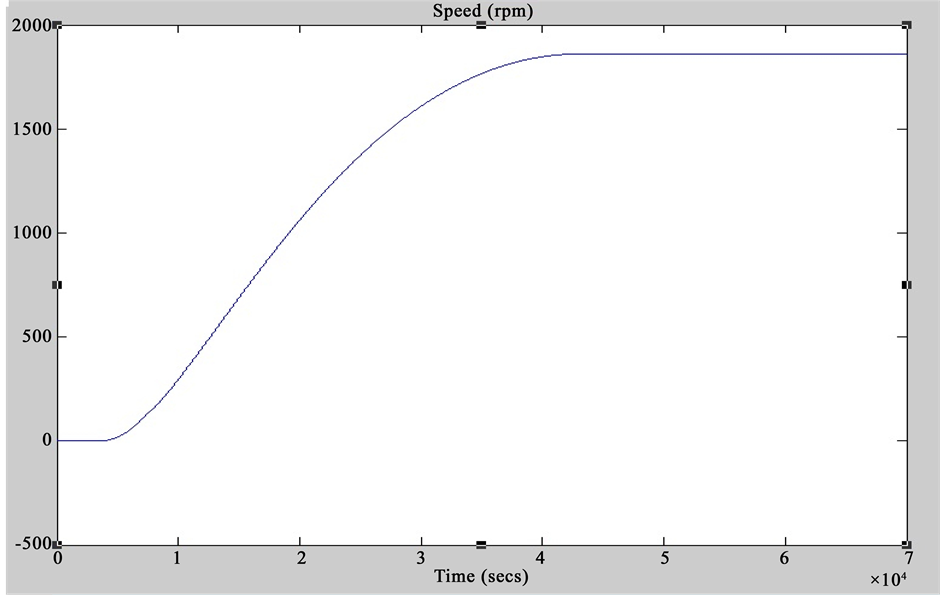
Figure 6. Speed regulation (rpm).
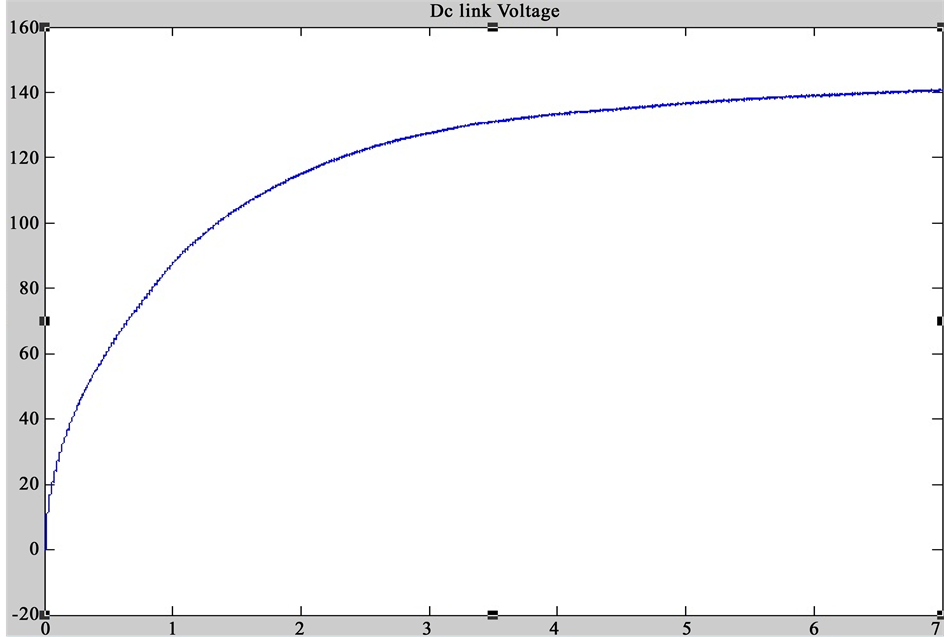
Figure 7. DC link voltage.
8. Conclusion
This investigation describes the significant difference between the PFC converters and their operating strategies. The converter features like conduction losses, stress across the semiconductor switches, Power Factor and Total Harmonic Distortion are checked using the MATLAB/Simulink platform and verified experimentally. The performance and efficiency of the three ac-dc converter vary according to the design. On simulating the circuit, the Buck-Boost converter reduces the stress across the switches but in order to reduce the stresses, the capacitance and inductance must be added which makes the circuit complex. The Cuk converter has the advantage of zero current turn on and zero current turn off. But the drawback is the floating switch and the step up voltage
Table 4. Motor Specifications.
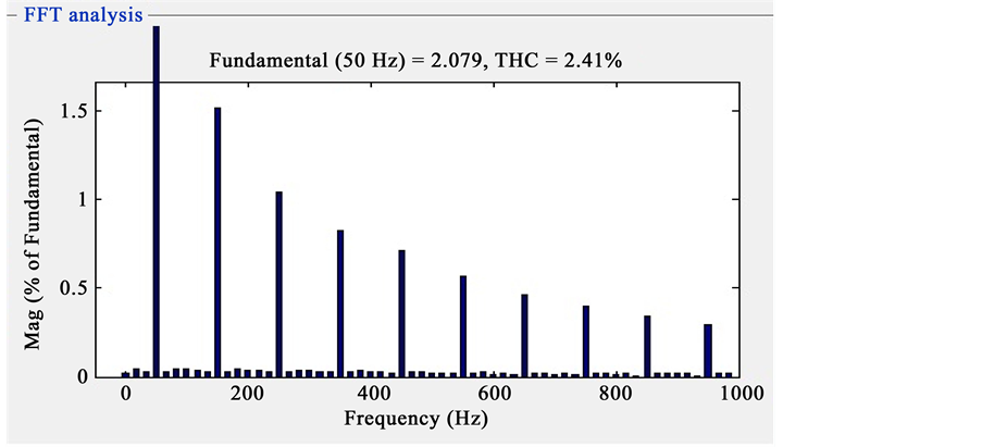
Figure 8. Harmonic spectra.
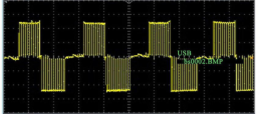
Figure 9. Gate pulses to the different switches.
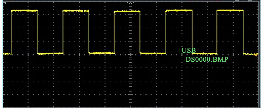
Figure 10. PWM pulses to the VSI.
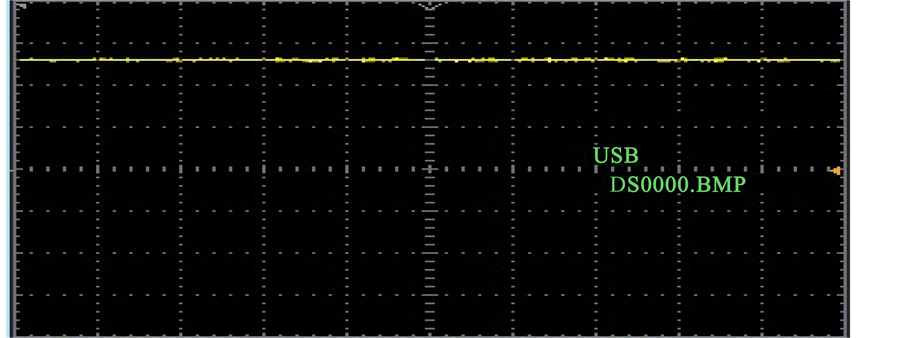
Figure 11. Output from the DC link voltage (Vdc).
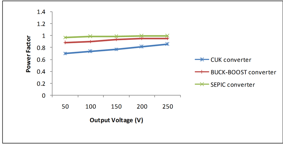
Figure 12. Comparison chart of different converters PF vs output voltage.
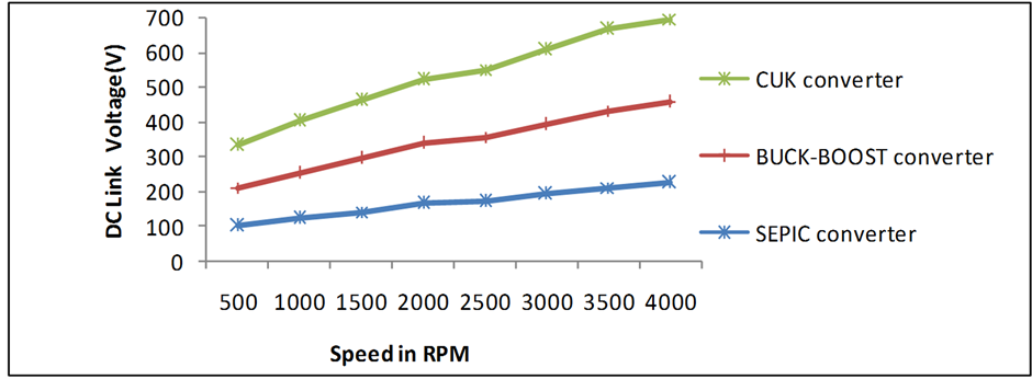
Figure 13. Comparison chart of different converters speed vs output voltage.
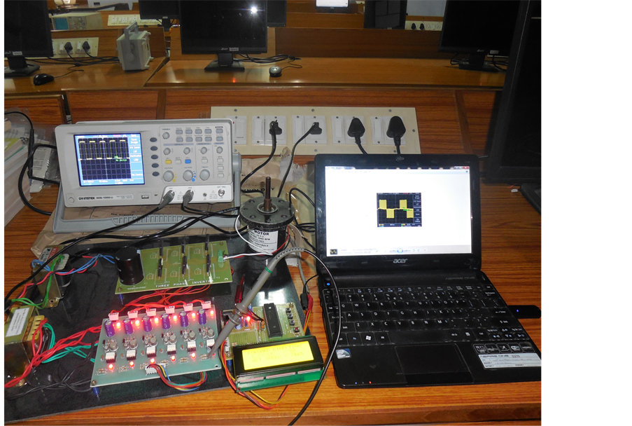
Figure 14. Hardware setup of proposed system.
rises to 2. While comparing these PFC converters, the Bridgeless SEPIC converter reduces the conduction losses, improves the Power Factor and the Harmonic Distortion are within the IEC 61000 3-2 limits. These features are verified experimentally and the Bridgeless SEPIC converter is economical on investigating the other ac-dc converters.
Cite this paper
Subramaniam Kaliappan,Dr. Ramachandran Rajeswari, (2016) An Investigation of Power Converters Fed BLDC Motor for Adjustable Speed. Circuits and Systems,07,1369-1378. doi: 10.4236/cs.2016.78020
References
- 1. Fardoun, A.A., Ismail, E.H., Sabzali, A.J. and Al-Saffar, M.A. (2012) New Efficient Bridgless Cuk Rectifiers for PFC Applications. IEEE Transactions on Power Electronics, 27, 3292-3301.
http://dx.doi.org/10.1109/TPEL.2011.2182662 - 2. Wei, H. and Batarseh, I. (1998) Comparison of Basic Converter Topologies for Power Factor Correction. Proceedings of IEEE ‘98 Southeastcon, Orlando, 24-26 April 1998, 348-353.
http://dx.doi.org/10.1109/SECON.1998.673368 - 3. Singh, B., Singh, B.N., Chandra, A., Al-Haddad, K., Pandey, A. and Kothari, D.P. (2003) A Review of Single-Phase Improved Power Quality Ac—Dc Converters. IEEE Transactions on Industrial Electronics, 50, 962-981.
http://dx.doi.org/10.1109/TIE.2004.825341 - 4. Chen, J., Maksimovic, D. and Erickson, R.W. (2006) Analysis and Design of a Low-Stress Buck-Boost Converter in Universal Input PFC Applications. IEEE Transactions on Power Electronics, 21, 320-329.
http://dx.doi.org/10.1109/TPEL.2005.869744 - 5. Gopalarathnam, T. and Toliyat, H.A. (2003) A New Topology for Unipolar Brushless Dc Motor Drive with High Power Factor. IEEE Transactions on Power Electronics, 18, 1397-1404.
http://dx.doi.org/10.1109/TPEL.2003.818873 - 6. Shao, J. (2006) An Improved Microprocessor-Based Sensor Less Brushless DC (BLDC) Motor Drive for Automotive Applications. IEEE Transactions on Industrial Electronics, 42, 1216-1221.
http://dx.doi.org/10.1109/TIA.2006.880888 - 7. Yang, J.-W. and Do, H.-L. (2013) Bridgeless SEPIC Converter with a Ripple-Free Input Current. IEEE Transactions on Power Electronics, 28, 3388-3393.
http://dx.doi.org/10.1109/TPEL.2012.2226607 - 8. Singh, S. and Singh, B. (2012) A Voltage-Controlled PFC Cuk Converter-Based BLDCM Drive for Air-Conditioner. IEEE Transactions on Industry Applications, 48, 832-838.
http://dx.doi.org/10.1109/TIA.2011.2182329 - 9. Singh, S. and Singh, B. (2011) Power Quality Improved PMBLDCM Drive for Adjustable Speed Application with Reduced Sensor Buck-Boost PFC Converter. The 4th ICETET Proceedings, 18, 180-184.
http://dx.doi.org/10.1109/ICETET.2009.111 - 10. Wu, T.-F. and Chen, Y.-K. (1998) Modeling PWM DC/DC Converters out of Basic Converter Units. IEEE Transactions on Power Electronics, 13, 870-881.
http://dx.doi.org/10.1109/63.712294 - 11. Bist, V. and Singh, B. (2014) A Adjustable-Speed PFC Bridgeless Buck-Boost Converter-Fed BLDC Motor Drive. IEEE Transactions on Industrial Electronics, 61, 2665-2677.
http://dx.doi.org/10.1109/TIE.2013.2274424 - 12. Bist, V. and Singh, B. (2015) PFC Cuk Converter Fed BLDC Motor Drive. IEEE Transactions on Industrial Electronics, 30, 871-887.
http://dx.doi.org/10.1109/TIE.2014.2384001 - 13. Chen, Y. and Dai, W.-P. (2013) Classification and Comparison of BPFC Techniques. Przeglqd Elektrotechniczny, 89, 179-186.
http://pe.org.pl/articles/2013/2a/39.pdf - 14. Jang, Y. and Jovanovic, M.M. (2011) Bridgeless High-Power-Factor Buck Converter. IEEE Transactions on Power Electronics, 26, 602-611.
http://dx.doi.org/10.1109/TPEL.2010.2068060