Paper Menu >>
Journal Menu >>
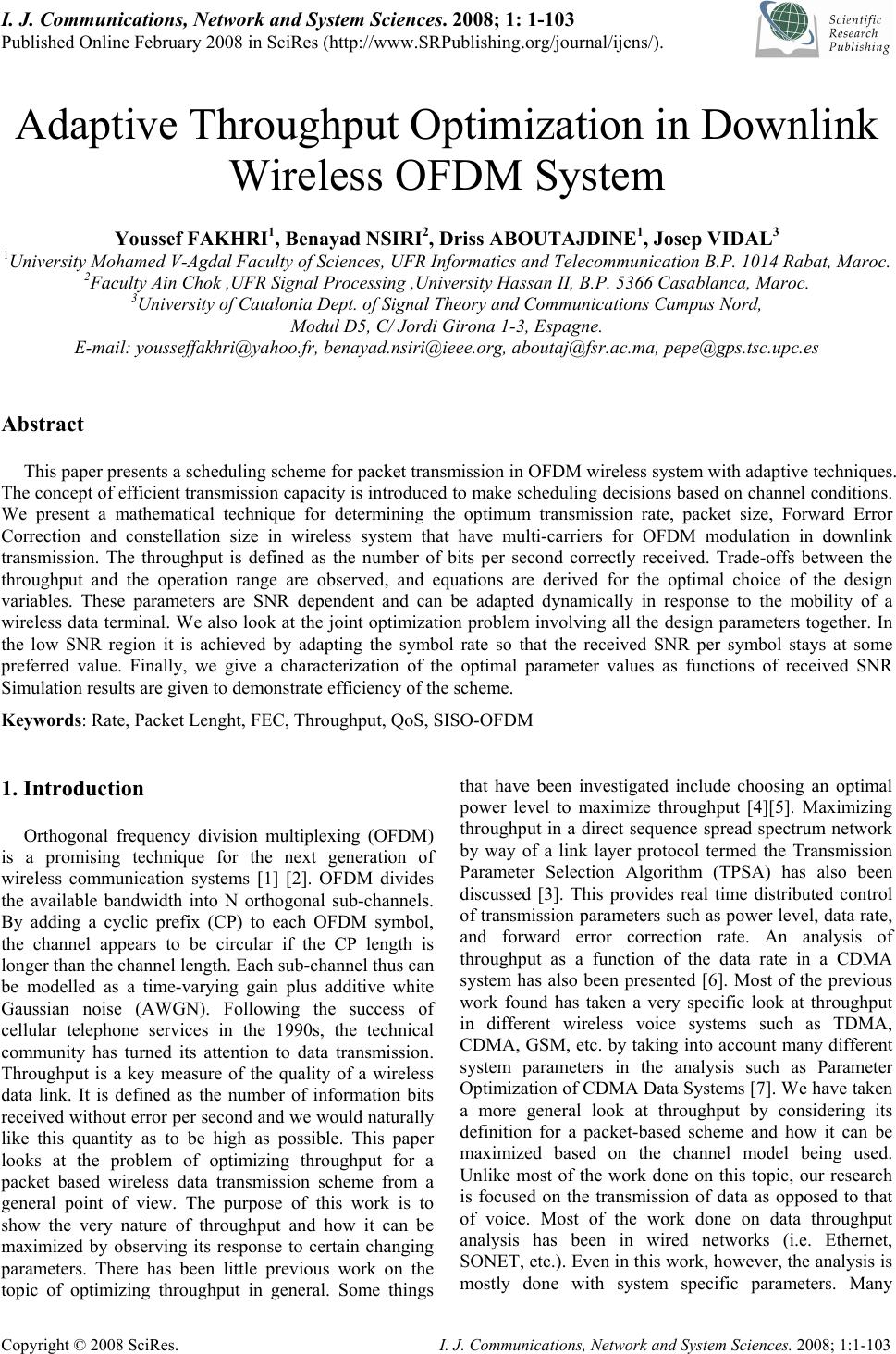 I. J. Communications, Network and System Sciences. 2008; 1: 1-103 Published Online February 2008 in SciRes (http://www.SRPublishing.org/journal/ijcns/). Copyright © 2008 SciRes. I. J. Communications, Network and System Sciences. 2008; 1:1-103 Adaptive Throughput Optimization in Downlink Wireless OFDM System Youssef FAKHRI1, Benayad NSIRI2, Driss ABOUTAJDINE1, Josep VIDAL3 1University Mohamed V-Agdal Faculty of Sciences, UFR Informatics and Telecommunication B.P. 1014 Rabat, Maroc. 2Faculty Ain Chok ,UFR Signal Processing ,University Hassan II, B.P. 5366 Casablanca, Maroc. 3University of Catalonia Dept. of Signal Theory and Communications Campus Nord, Modul D5, C/ Jordi Girona 1-3, Espagne. E-mail: yousseffakhri@yahoo.fr, benayad.nsiri@ieee.org, aboutaj@fsr.ac.ma, pepe@gps.tsc.upc.es Abstract This paper presents a scheduling scheme for packet transmission in OFDM wireless system with adaptive techniques. The concept of efficient transmission capacity is introduced to make scheduling decisions based on channel conditions. We present a mathematical technique for determining the optimum transmission rate, packet size, Forward Error Correction and constellation size in wireless system that have multi-carriers for OFDM modulation in downlink transmission. The throughput is defined as the number of bits per second correctly received. Trade-offs between the throughput and the operation range are observed, and equations are derived for the optimal choice of the design variables. These parameters are SNR dependent and can be adapted dynamically in response to the mobility of a wireless data terminal. We also look at the joint optimization problem involving all the design parameters together. In the low SNR region it is achieved by adapting the symbol rate so that the received SNR per symbol stays at some preferred value. Finally, we give a characterization of the optimal parameter values as functions of received SNR Simulation results are given to demonstrate efficiency of the scheme. Keywords: Rate, Packet Lenght, FEC, Throughput, QoS, SISO-OFDM 1. Introduction Orthogonal frequency division multiplexing (OFDM) is a promising technique for the next generation of wireless communication systems [1] [2]. OFDM divides the available bandwidth into N orthogonal sub-channels. By adding a cyclic prefix (CP) to each OFDM symbol, the channel appears to be circular if the CP length is longer than the channel length. Each sub-channel thus can be modelled as a time-varying gain plus additive white Gaussian noise (AWGN). Following the success of cellular telephone services in the 1990s, the technical community has turned its attention to data transmission. Throughput is a key measure of the quality of a wireless data link. It is defined as the number of information bits received without error per second and we would naturally like this quantity as to be high as possible. This paper looks at the problem of optimizing throughput for a packet based wireless data transmission scheme from a general point of view. The purpose of this work is to show the very nature of throughput and how it can be maximized by observing its response to certain changing parameters. There has been little previous work on the topic of optimizing throughput in general. Some things that have been investigated include choosing an optimal power level to maximize throughput [4][5]. Maximizing throughput in a direct sequence spread spectrum network by way of a link layer protocol termed the Transmission Parameter Selection Algorithm (TPSA) has also been discussed [3]. This provides real time distributed control of transmission parameters such as power level, data rate, and forward error correction rate. An analysis of throughput as a function of the data rate in a CDMA system has also been presented [6]. Most of the previous work found has taken a very specific look at throughput in different wireless voice systems such as TDMA, CDMA, GSM, etc. by taking into account many different system parameters in the analysis such as Parameter Optimization of CDMA Data Systems [7]. We have taken a more general look at throughput by considering its definition for a packet-based scheme and how it can be maximized based on the channel model being used. Unlike most of the work done on this topic, our research is focused on the transmission of data as opposed to that of voice. Most of the work done on data throughput analysis has been in wired networks (i.e. Ethernet, SONET, etc.). Even in this work, however, the analysis is mostly done with system specific parameters. Many 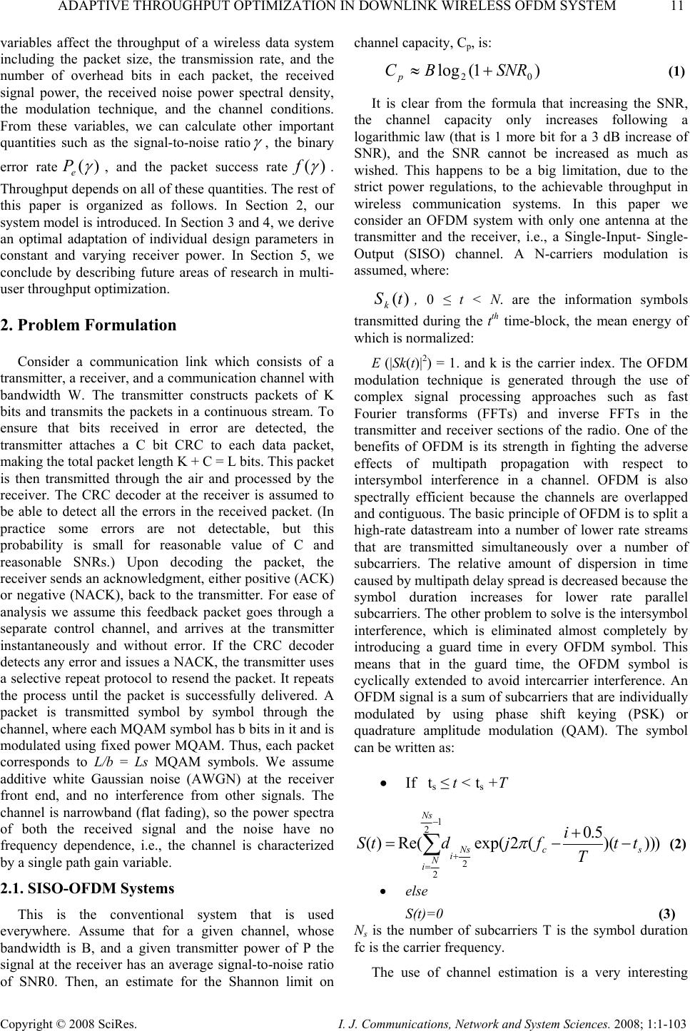 ADAPTIVE THROUGHPUT OPTIMIZATION IN DOWNLINK WIRELESS OFDM SYSTEM 11 Copyright © 2008 SciRes. I. J. Communications, Network and System Sciences. 2008; 1:1-103 variables affect the throughput of a wireless data system including the packet size, the transmission rate, and the number of overhead bits in each packet, the received signal power, the received noise power spectral density, the modulation technique, and the channel conditions. From these variables, we can calculate other important quantities such as the signal-to-noise ratio γ , the binary error rate)( γ e P, and the packet success rate)( γ f. Throughput depends on all of these quantities. The rest of this paper is organized as follows. In Section 2, our system model is introduced. In Section 3 and 4, we derive an optimal adaptation of individual design parameters in constant and varying receiver power. In Section 5, we conclude by describing future areas of research in multi- user throughput optimization. 2. Problem Formulation Consider a communication link which consists of a transmitter, a receiver, and a communication channel with bandwidth W. The transmitter constructs packets of K bits and transmits the packets in a continuous stream. To ensure that bits received in error are detected, the transmitter attaches a C bit CRC to each data packet, making the total packet length K + C = L bits. This packet is then transmitted through the air and processed by the receiver. The CRC decoder at the receiver is assumed to be able to detect all the errors in the received packet. (In practice some errors are not detectable, but this probability is small for reasonable value of C and reasonable SNRs.) Upon decoding the packet, the receiver sends an acknowledgment, either positive (ACK) or negative (NACK), back to the transmitter. For ease of analysis we assume this feedback packet goes through a separate control channel, and arrives at the transmitter instantaneously and without error. If the CRC decoder detects any error and issues a NACK, the transmitter uses a selective repeat protocol to resend the packet. It repeats the process until the packet is successfully delivered. A packet is transmitted symbol by symbol through the channel, where each MQAM symbol has b bits in it and is modulated using fixed power MQAM. Thus, each packet corresponds to L/b = Ls MQAM symbols. We assume additive white Gaussian noise (AWGN) at the receiver front end, and no interference from other signals. The channel is narrowband (flat fading), so the power spectra of both the received signal and the noise have no frequency dependence, i.e., the channel is characterized by a single path gain variable. 2.1. SISO-OFDM Systems This is the conventional system that is used everywhere. Assume that for a given channel, whose bandwidth is B, and a given transmitter power of P the signal at the receiver has an average signal-to-noise ratio of SNR0. Then, an estimate for the Shannon limit on channel capacity, Cp, is: )1(log 02 SNRBC p + ≈ (1) It is clear from the formula that increasing the SNR, the channel capacity only increases following a logarithmic law (that is 1 more bit for a 3 dB increase of SNR), and the SNR cannot be increased as much as wished. This happens to be a big limitation, due to the strict power regulations, to the achievable throughput in wireless communication systems. In this paper we consider an OFDM system with only one antenna at the transmitter and the receiver, i.e., a Single-Input- Single- Output (SISO) channel. A N-carriers modulation is assumed, where: )(tSk, 0 ≤ t < N. are the information symbols transmitted during the tth time-block, the mean energy of which is normalized: E (|Sk(t)|2) = 1. and k is the carrier index. The OFDM modulation technique is generated through the use of complex signal processing approaches such as fast Fourier transforms (FFTs) and inverse FFTs in the transmitter and receiver sections of the radio. One of the benefits of OFDM is its strength in fighting the adverse effects of multipath propagation with respect to intersymbol interference in a channel. OFDM is also spectrally efficient because the channels are overlapped and contiguous. The basic principle of OFDM is to split a high-rate datastream into a number of lower rate streams that are transmitted simultaneously over a number of subcarriers. The relative amount of dispersion in time caused by multipath delay spread is decreased because the symbol duration increases for lower rate parallel subcarriers. The other problem to solve is the intersymbol interference, which is eliminated almost completely by introducing a guard time in every OFDM symbol. This means that in the guard time, the OFDM symbol is cyclically extended to avoid intercarrier interference. An OFDM signal is a sum of subcarriers that are individually modulated by using phase shift keying (PSK) or quadrature amplitude modulation (QAM). The symbol can be written as: • If ts ≤ t < ts +T ))))( 5.0 (2exp(Re()( 1 2 2 2 ∑ − =+− + −= Ns N i scNs i tt T i fjdtS π (2) • else S(t)=0 (3) Ns is the number of subcarriers T is the symbol duration fc is the carrier frequency. The use of channel estimation is a very interesting  12 Y. FAKHRI ET AL. Copyright © 2008 SciRes. I. J. Communications, Network and System Sciences. 2008; 1:1-103 function to be added to the receiver to make the system more resistant to fading and Doppler effects, over all, if it is going to be used aboard of cars in a highway. Wireless LAN is a very important application for OFDM and the development of the standard promises to have not only a big market but also application in many different environments. 2.2. Throughput Analysis The total throughput of the system, T, is the sum of the individual throughputs of the sub-carriers i operating simultaneously in the system. Since we are considering a OFDM system with N sub- carriers. With the above simplifying assumptions, we define the throughput of a system as the number of payload bits per second received correctly [8],[9]: )(** 1 ii N i fR L CL T γ ∑ = − = (4) where i R is the symbol rate assigned to sub-carriers i, )( i f γ is the packet success rate (PSR) defined as the probability of receiving a packet correctly, and i γ is the SNR given by: i i iRN P * 0 = γ (5) where N0 the one-sided noise power spectral density, and i P the received power in sub-carriers i. 3. Throughput Optimization 3.1. Optimal Symbol Rate To find the symbol rate is R that maximizes throughput, we differentiate (4) with respect to is Rand set it to zero to obtain the following condition. i i idR d d df R L CL f L CL dR dT γ γ γ γ )( )( − + − = (6) ))( )( )((2 0i i i iRN P d df Rf L CL dR dT − + − = γ γ γ (7) Next we set the derivative to zero 0 )( )()( 0 =− γ γ γ d df RN P f i i (8) γ γ γγ d df f)( )( = (9) We adopt the notation * γγ = for a signal to noise ration that satisfies equation (9). Since any symbol error in the packet results in a loss of the packet, the PSR f is given in terms of the symbol error rate e Pby: b L e Pf )](1[)(* γγ −= (10) Combining these two, we arrive at an equation for obtaining the preferred SNR per symbol* γ : bL P d dP ee / )](1[)( * * * γ γ γ γγγ − −= = (11) where Pe of MQAM in AWGN channels is (approximately) given by [8]: ) 12 3 ()21(4)(2 γγ − −=− b b eQP (12) Once * γ is determined, the optimal symbol rate is obtained from (5). 0 * * N P Ri i γ = (13) Note that the solution * γ in equations (10) and (11) depends on only design parameters b and L, but is independent of the received power level. In essence, the adaptive system monitors γ , and upon deviation from its internally preset value γ , changes its symbol rate such that * γγ =. Figure 1 shows the spectral efficiency T/W versus received SNR for different symbol rates. Where W the bandwidth required for transmission of )2(log2 b b= information bits. We see that the system can support high symbol rates at high SNR, but its throughput rapidly decreases at a certain SNR value below which the system should switch to a lower symbol rate to maintain the optimal throughput. The optimal curve is obtained by adapting Ri to keep γ =* γ . 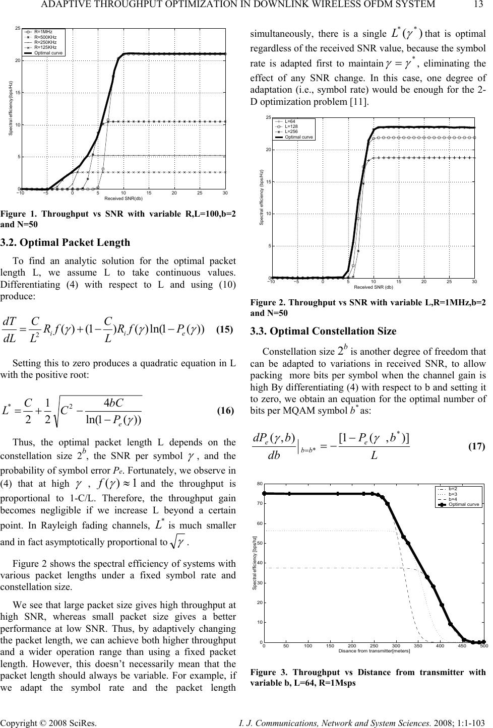 ADAPTIVE THROUGHPUT OPTIMIZATION IN DOWNLINK WIRELESS OFDM SYSTEM 13 Copyright © 2008 SciRes. I. J. Communications, Network and System Sciences. 2008; 1:1-103 −10−50510 15 20 25 30 0 5 10 15 20 25 Received SNR(db) Spectral efficiency(bps/Hz) R=1MHz R=500KHz R=250KHz R=125KHz Optimal curve Figure 1. Throughput vs SNR with variable R,L=100,b=2 and N=50 3.2. Optimal Packet Length To find an analytic solution for the optimal packet length L, we assume L to take continuous values. Differentiating (4) with respect to L and using (10) produce: ))(1ln()()1()( 2 γγγ eii PfR L C fR L C dL dT −−+= (15) Setting this to zero produces a quadratic equation in L with the positive root: ))(1ln( 4 2 1 2 2* γ e P bC C C L− −+= (16) Thus, the optimal packet length L depends on the constellation size 2b, the SNR per symbol γ , and the probability of symbol error Pe. Fortunately, we observe in (4) that at high γ , 1)( ≈ γ fand the throughput is proportional to 1-C/L. Therefore, the throughput gain becomes negligible if we increase L beyond a certain point. In Rayleigh fading channels, * L is much smaller and in fact asymptotically proportional to γ . Figure 2 shows the spectral efficiency of systems with various packet lengths under a fixed symbol rate and constellation size. We see that large packet size gives high throughput at high SNR, whereas small packet size gives a better performance at low SNR. Thus, by adaptively changing the packet length, we can achieve both higher throughput and a wider operation range than using a fixed packet length. However, this doesn’t necessarily mean that the packet length should always be variable. For example, if we adapt the symbol rate and the packet length simultaneously, there is a single )(** γ Lthat is optimal regardless of the received SNR value, because the symbol rate is adapted first to maintain* γγ =, eliminating the effect of any SNR change. In this case, one degree of adaptation (i.e., symbol rate) would be enough for the 2- D optimization problem [11]. −10−50510 15 20 25 30 0 5 10 15 20 25 Received SNR (db) Spectral efficiency (bps/Hz) L=64 L=128 L=256 Optimal curve Figure 2. Throughput vs SNR with variable L,R=1MHz,b=2 and N=50 3.3. Optimal Constellation Size Constellation size 2b is another degree of freedom that can be adapted to variations in received SNR, to allow packing more bits per symbol when the channel gain is high By differentiating (4) with respect to b and setting it to zero, we obtain an equation for the optimal number of bits per MQAM symbol b* as: L bP db bdPe bb e)],(1[),(* * γγ − −= = (17) 050100 150 200 250 300 350 400 450 500 0 10 20 30 40 50 60 70 80 Disance from transmitter[meters] Spectral efficiency [bps/hz] b=2 b=3 b=4 Optimal curve Figure 3. Throughput vs Distance from transmitter with variable b, L=64, R=1Msps  14 Y. FAKHRI ET AL. Copyright © 2008 SciRes. I. J. Communications, Network and System Sciences. 2008; 1:1-103 Figure 3 shows the spectral efficiency of systems with various constellation sizes under fixed symbol rate and packet length in AWGN channels. Higher level modulations using MQAM mainly increase the throughput at high low distance, but have shorter communication ranges. By adapting the constellation size, therefore, we can boost the throughput at low distance while maintaining the same performance at high distance. 4. Throughput Optimization using Forward Error Correction 4.1. Forward Error Correction Throughput Equations We will denote the number of information bits in the packet as K, and the number of CRC bits as C. L is defined as K+C. Now instead of transmitting those L bits with no error correction capability, we will now add B error correcting bits and transmit a total of L+B bits. Using a block code forward error correction scheme, the minimum number of bits B required to correct t errors is given by [12]: Bkt k n BL n ≤ ⎪ ⎭ ⎪ ⎬ ⎫ ⎪ ⎩ ⎪ ⎨ ⎧ ⎟ ⎟ ⎠ ⎞ ⎜ ⎜ ⎝ ⎛ ⎟ ⎟ ⎠ ⎞ ⎜ ⎜ ⎝ ⎛ =∑ = + 0 2 logmax (18) Now that we can correct t errors, our packet success rate, )( γ f should be larger than its previous value with no error correction. Recall that )( γ f with t=0 is given by: b L ie Pf )](1[)( γγ −= (19) where )( γ e P is the probability of a bit error as a function of the SNR. Now, with error correction capability, the packet success rate for some arbitrary value of t is [13]: () nBL ie t n i n e BL n PPf −+ = + − ⎟ ⎟ ⎠ ⎞ ⎜ ⎜ ⎝ ⎛ =∑)](1[ )( 0 γγγ (20) Our new equation for the throughput as a function of the signal to noise ratio is: )(* / *0 1 it i N i f NP BL CL T γ γ ∑ =+ − = (21) 4.2. Optimum Error Correction If we plot equation (21) for different values of t using MQAM in AWGN channels we get a very interesting result. Figure (4) shows the throughput for t=0, 20, 60,100. In each of these plots, P/N0 is fixed at 5*106 and C at 16 bits, N=50, b=1. Perhaps the most important thing to note in this graph is that there is an optimum value for t at which higher values of t will not produce higher throughput. From this graph the throughput appears to reach an optimum value somewhere around t=20. 0 1 2 3 4 5 6 7 8 910 0 2 4 6 8 10 12 14 16 18 x 107 SNR(db) Throughput[bits per second] t=100 t=60 t=20 t=0 Figure 4. Throughput vs SNR (L=216,N=50) 5. Conclusion Maximizing throughput in a wireless channel is a very important aspect in the quality of a voice or data transmission. In this paper, we have shown that factors such as the optimum packet length and optimum transmission rate are all functions of the signal to noise ratio. These equations can be used to find the optimum signal to noise ratio that the system should be operated at to achieve the maximum throughput. The key concept behind this research is that for each particular channel (AWGN or Rayleigh) and transmission scheme))(( γ e P, there exists a specific value for the signal to noise ratio to maximize the throughput. Once the probability of error, )( γ e Pis known, this optimal SNR value can be obtained. The optimal values depend on the received signal strength. At low SNR, the throughput is maximized by adapting the symbol rate while using the smallest constellation size and some fixed packet length. Finally, we have characterized the optimal adaptation of the parameters in AWGN under restrictions on the values that the parameters can take. Our optimization framework is very general and can be applied to any systems where the combination of FEC, adaptive modulation, and packet length can be adapted to maximize throughput. The analysis and intuition in this paper, however, apply to single user systems. Typical multi-user systems are interference-limited and should be dealt with differently. For example, schemes that enable orthogonal channel sharing among users through frequency (variable symbol rate), time (time division multiplexing), or code division  ADAPTIVE THROUGHPUT OPTIMIZATION IN DOWNLINK WIRELESS OFDM SYSTEM 15 Copyright © 2008 SciRes. I. J. Communications, Network and System Sciences. 2008; 1:1-103 (spread spectrum modulation) may have an advantage over the other schemes (variable packet length and/or adaptive FEC). 6. References [1] H. Sampath, S. Talwar, J. Tellado, V. Erceg, and A. Paulraj, A Fourthgeneration MIMO-OFDM Broadband Wireless System: Design, Performance, and Field Trial Results, IEEE Communications Magazine, vol. 40, no. 9, pp. 143-149, 2002. [2] T.S. Rappaport, A. Annamalai, R. M. Buehrer, and W. H. Tranter, Wireless Communications: Past Events and a Future Perspective, IEEE Communications Magazine, pp. 148-161, May 2002. [3] J. A. C. Bingham, Multicarrier Modulation for Data Transmisson: an Idea whose Time Has Come, IEEE Communications Magazine, vol. 28, no. 5, pp. 5-14, May 1990. [4] W. T. Webb and R. Steele, Variable rate QAM for mobile radio, IEEE Trans. on Commun., vol. 43, pp. 2223-2230, July 1995. [5] Y.Fakhri,D.Aboutajdine,J.Vidal. Multicarrier power allocation for maximum throughput in delayed channel knowledge conditions. Proc. Of International Workshop on Wireless Communication in Underground and Confined Areas IWWCUCA2005, Val-dor, Quebec, Canada, Juin 6- 7, 2005. [6] J. Goldsmith and S.-G. Chua, Adaptive coded modulation for fading channels, IEEE Trans. Commun., vol. 46, pp. 595-602, May 1998. [7] H. Matsuoka, S. Sampei, N. Morinaga, and Y. Kamio, Adaptive modulation system with variable coding rate concatenated code for high quality multi-media communication systems, IEICE Trans. Commun., vol. E79-B, pp. 328-334, Mar. 1996. [8] M. B. Pursley and J. M. Shea, Adaptive non uniform phase-shift-key modulation for multimedia traffic in wireless networks, IEEE J. Select. Areas Commun, vol. 18, pp. 1394-1407, Aug. 2000. [9] S. Catreux, P. F. Driessen, and L. J. Greenstein, Data throughputs using multiple-input multiple- output (MIMO) techniques in a noiselimited cellular environment, IEEE Trans. Wireless Commun., vol. 1, pp. 226-235, Apr. 2002. [10] J. G. Proakis, Digital Communications, 4th Ed, New York: McGraw-Hill, 2000. [11] S. T. Chung, A. Goldsmith, Degrees of freedom in adaptive modulation:a unified view, IEEE Trans. Commun., vol. 49, pp. 1561-1571, Sep. 2001. [12] Clark,George C., Jr., Cain, J. Bibb, Error-Correction Coding for Digital Communications. Plenum Press, NY, 1981. p38. [13] Clark,George C., Jr., Cain, J. Bibb, Error-Correction Coding for Digital Communications. Plenum Press, NY, 1981. p219. |