Journal of Electromagnetic Analysis and Applications
Vol. 5 No. 9 (2013) , Article ID: 37338 , 5 pages DOI:10.4236/jemaa.2013.59056
MRI-Induced Tissue Heating at Metallic Sutures (Cerclages)*
![]()
1Institute of Health Care Engineering with European Notified Body of Medical Devices, Graz University of Technology, Graz, Austria; 2University Clinic of Radiology, Medical University of Graz, Graz, Austria.
Email: #norbert.leitgeb@tugraz.at
Copyright © 2013 Norbert Leitgeb et al. This is an open access article distributed under the Creative Commons Attribution License, which permits unrestricted use, distribution, and reproduction in any medium, provided the original work is properly cited.
Received June 28th, 2013; revised July 31st, 2013; accepted August 19th, 2013
Keywords: metallic implants; health risk; tissue damage; safety; radio frequency electromagnetic fields
ABSTRACT
Magnetic resonance imaging (MRI) has become an important diagnostic tool with an ongoing dynamic development towards application of increasing static magnetic flux densities and consequently, exposures to electromagnetic fields (EMF) of increasing radio frequencies (RF). This raises particular concern metallic implants could lead to excess tissue heating and consequently, to thermal tissue damage. In thorax surgery the intersected sternum is reconnected by metallic sutures (cerclages). To investigate whether patients with such implants can be accepted for MRI and whether there may be limitations with regard to static magnetic fields, by numerical anatomical and thermal modelling MRI induced tissue heating was assessed for magnetic flux densities 1.5 T, 3 T, 4 T and 7 T. Results show that overall tissue temperature increased with increasing RF EMF frequency. However, even for setting MRI exposure parameters at maximum permissible level partial body heating remained marginally affected and even at local level the additional contribution of the presence of the metallic cerclage remained below 1˚C. This allows concluding that from a heating point of view metallic sutures as used to fix the sternum after thorax surgery are no contraindication for MRI with static magnetic flux densities up to 7 T.
1. Introduction
Magnetic resonance imaging (MRI) has become an important diagnostic tool with an ongoing dynamic development towards application of increasingly higher static magnetic flux densities. In addition to static magnetic fields and rapidly switched gradient magnetic fields, MRI exposes patients also to radio frequency (RF) electromagnetic fields (EMF) which induce tissue heating. Due to physical laws the frequency of RF EMF proportionally increases with static magnetic flux densities by 42.6 MHz/Tesla. Consequently, tissue heating increases with increasing static field levels. Particular concern is raised about MR imaging of patients with metallic implants and the associated risk of excess tissue heating and subsequent thermal tissue damage. Studies concentrating on 1.5 T MRI showed that tissue heating critically depends on size, shape and orientation of metallic implants. However, reported quantitative results were quite different. Metallic implants were considered acceptable for MRI based on calculated temperature elevations below 1.5˚C [1-3] while others concluded they were counterindicated because of calculated temperature elevations up to some 13˚C. Highest temperature increases were reported at tips of straight metallic wires [4-8]. Particular concern was also raised with regard to implanted metallic loops [9]. The diverging results demonstrate the need for case-by-case risk assessment.
In thorax surgery the dissected sternum is reconnected by metallic sutures (cerclages) in terms of metallic wires wrapped around the bone (Figure 1). Therefore, it needs to be analysed whether patients with such metallic implants could be accepted for MRI in particular at higher static magnetic flux densities. This paper quantitatively investigates potential health risks with regard to excess tissue heating.
2. Method
Based on X-ray images cerclages were modelled by elliptic metallic wire loops which were numerically in-
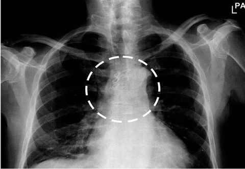
Figure 1. Post surgery X-ray thorax image with metallic sutures (cerclages).
serted into a numerical anatomical model of a 34-yearold adult man (DUKE, 180 cm height, 72.25 kg body mass), segmented into 1 × 1 × 1 mm voxels and 84 different tissues [10]. Dielectric values of body tissue parameters were taken from [11-13]. This anatomical model was placed into a numerical model of frequency-specific resonant birdcage coils to represent the source of RF EMF used for MRI. The induced intracorporal distributions of the rate of specific energy absorption (SAR) were calculated with a commercial software package SEMCAD X (speag, Zeughausstrasse 438004 Zürich Switzerland) by solving Maxwell’s equations by the well established FTDT (finite-difference time-domain) method.
Tissue heating is caused by two sources, by RF EMF directly absorbed by the tissue and by the direct and indirect effects of the metallic implant such as Ohm’s power loss caused by induced electric eddy currents within the wire, and local field enhancement due to electric field distortion. Calculation was performed in two steps. First, the intracorporal SAR distribution was calculated. In a second step, the resulting temperature elevation after 30 min exposure was determined by a selfwritten software based on the modified bioheat equation [14] which allowed accounting also for dynamic physiologic thermoregulatory responses. While the well-known bio-heat equation [15] estimates tissue heating under steady state conditions and considers heat transfer by simplified static terms for metabolic heat generation and heat dissipation by conduction and perfusion only, the used modified thermal model allowed not only accounting for dynamic changes of metabolism and blood perfusion but also for additional thermoregulatory mechanisms such as heat exchange at tissue/air interfaces (within the lung, the respiratory tract and at the body surface) as well as for cooling by insensible water loss, by radiative heat dissipation and by sweating.
Calculations were made at magnetic flux densities 1.5 T, 3 T, 4 T and 7 T with RF EMF emissions scaled to the highest permissible level as defined in the specific MRI device safety standard [16] for normal operation mode and for MRI exposure limits recommended by the International Commission on Non Ionizing Radiation Protection (ICNIRP), respectively [17,18]. The specific absorption rates in particular the partial body SAR which is averaged over the exposed part of the body (SARPB) are limited depending on the ratio of exposed partial body mass MPB to the whole body mass MWB as follows

From this, the maximum permitted SARPB for the exposed anatomical model resulted in 7 W/kg.
The cerclage was characterised by physical parameters and dimensions as listed in the data sheet of cerclages used in medical surgery, in particular a stainless steel nonabsorbable suture with 0.8 mm diameter (Syneture Monofilament 316L).
Wire heating was calculated with two approaches. First, a simplified theoretical approach was used based on Faraday’s law of induction which is frequently chosen in the literature but ignores retroactions of induced eddy currents (extremely low frequency (ELF) simplification) which results in eddy currents which remain constant over the wire’s cross section. Second, a more realistic RF approach based on Maxwell’s equations was used which accounted for the retroaction of RF eddy currents with consequential displacement of eddy currents towards the wire’s surface (skin effect).
To assure comparability of results, numerical calculations were made with identical modelling including meshing to calculate heating with and without the cerclage just by assigning to cerclage-related voxels dielectric properties of either body tissue or stainless steel, respectively.
In addition, also potential excess heating in the single fault condition in terms of breakage of the cerclage was investigated which could cause high current densities interacting with biological fluids or tissue entering the gap. In this case to avoid limitations in spatial resolution analytical calculations were performed at loop models immersed in homogeneous tissue.
3. Results
Due to the presence of the metallic cerclage additional tissue heating is caused by three different mechanisms: First, by directly heating the wire due to Ohm’s power loss caused by induced electric eddy currents. Second, by distorting and concentrating the electric field component of the RF EMF caused by the metallic implant. This subsequently increases local SAR. Third, by altering pathways of intracorporal eddy currents induced by RF EMF. The results demonstrate that temperature elevation caused by the presence of the cerclage is moderate. The locally increased SAR and the associated temperature change around the cerclage can be seen in the distributions of SAR presented in Figure 2 and tissue temperature shown in Figure 3 within a cross-sectional plane across the cerclage.
For quantitative assessment the temperature distribution along a line across the cerclage calculated for 1.5 T MRI is shown in Figure 3 without and with the cerclage. The wire heating was calculated both with the ELF and RF approach, respectively. It can be seen that the impact of the cerclage on SAR and temperature distribution remains restricted to the adjacent region only and that the simplified ELF approach considerably overestimates heating compared to the more realistic RF approach (Figure 4).
As a consequence of the RF skin-effect, Ohm’s heating of the wire loop reduces with increasing frequency. Therefore, it does no longer increase with the square of frequency (f2) but with the lower exponent (f3/2). This explains why the temperature increase is smaller in the more realistic RF approach which accounts for the RF skin effect. Under such realistic conditions at 1.5 T, at the cerclage maximum tissue temperature increase was up to 0.85˚C. In contrast, ignoring the RF skin effect leads to overestimating heating by 80% and to a temperature increase of up to 1.53˚C (Figure 4).
Tissue heating was investigated for MRI with static magnetic flux densities 1.5 T, 3 T, 4 T and 7 T. These magnetic field levels were associated with magnetic resonance RF EMF frequencies of 63.9 MHz, 127.8 MHz, 170.4 MHz and 298.2 MHz, respectively. As expected, with increasing frequency the RF skin effect becomes increasingly relevant and so does the difference of calculated temperature changes of the RF and ELF approach. Overall, the tissue temperature increased with increasing RF EMF frequency, but the additional contribution due to the presence of the cerclage remained below 1˚C (Figure 5).
The investigation of the single fault condition, namely breakage of the cerclage revealed that this causes appearance of a section of poorer tissue conductivity within the electric eddy current pathway. Since electric conductivity is much poorer within tissue compared to the metallic wire, this reduces the electric eddy current amplitude but also concentration of the heating within the small volume of the gap which decreases with increasing gap length. The results of analytical modelling showed that already at gap lengths larger than 0.1 mm the resulting SAR within the gap becomes lower than the local SAR maximum encountered around the uninterrupted wire (Figure 6). Therefore, the single fault condition breakage of the cerclage does not cause unacceptable risks.
4. Discussion
The numerical calculation is based on well-established

Figure 2. Distribution of the specific absorption rate (SAR) in a cross sectional plane across the cerclage, calculated for 3 T MRI.
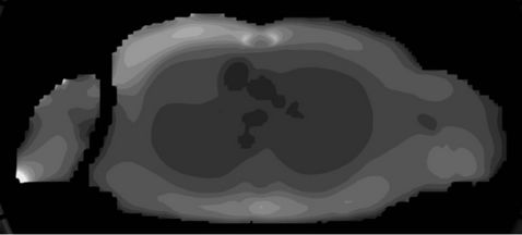
Figure 3. Distribution of tissue temperature in a cross sectional plane across the cerclage, calculated for 3 T MRI. To indicate isothermal lines the number of grey scales was reduced for temperature presentation.
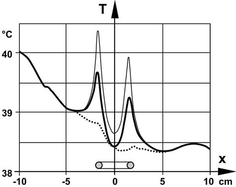
Figure 4. Temperature distribution along the centre line across the cerclage calculated for 1.5 T MRI. Dotted line … without cerclage, full thick line ![]() cerclage heating based on RF skin effect, full thin line ¾ cerclage heating based on ELF approach with ignored skin effect.
cerclage heating based on RF skin effect, full thin line ¾ cerclage heating based on ELF approach with ignored skin effect.
numerical models with fairly good spatial resolution. However, any modelling whether numerical or not is inherently suffering from unavoidable simplifications and restrictions which lead to deviations from the real world, and consequently to uncertainties [19]. In the presented study, sources of uncertainty may be discretization, meshing, computational space limitation, boundary
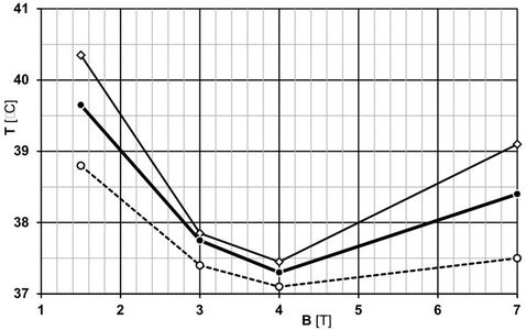
Figure 5. Maximum tissue temperatures at cerclages without the implant (broken line) and with the heated metallic cerclage calculated with the simplified ELF approach (diamonds) and with the realistic RF approach accounting for electromagnetic skin-effects (circles).
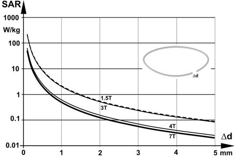
Figure 6. Calculated specific absorption rate (SAR) in the single fault condition of a gap of the implanted metallic cerclage, depending on the gap width Δd.
conditions, physical tissue properties, and computational algorithms, both for EMF interaction, heating and thermal regulation. To minimize these uncertainties, a high spatial resolution of 1 mm of the anatomical model was chosen, which among others allowed minimizing staircase effects. Meshing was made such as to avoid compromising the high spatial resolution. Boundary conditions were non-reflective and isothermal. This allowed limiting modelling uncertainty to about 1% [20]. The uncertainty with regard to tissue properties is caused by their measurement, extrapolation from analysed animal tissues to human tissue, and interpersonal variability. The related uncertainty can be estimated to about 10% - 15% for physical and about 10% for thermal parameters, respectively [12,13]. The uncertainty of the numerical algorithm was minimized by carefully setting the termination criteria. It can be estimated to less than 5% [21]. These contributions result in an overall uncertainty of about 19%.
The results are in good agreement with existing literature. Diverging results in particular those reporting higher temperature increases can be explained by overestimations due to application of the simplified ELF induction approach and by ignoring dynamic thermoregulatory responses due to static thermal modelling. The presented results and basic physics show that accounting for the RF EMF skin effect leads to lower heating. This can be explained by the fact that RF EMF induction is associated with a reduction of the effective cross sectional area of the wire and consequential increase of the electric loop resistance. At sufficiently high RF frequencies the full wire conducts electric currents like a hollow tube with a wall thickness inversely proportional to the root of EMF frequency. As a consequence, with increasing frequency the electric resistance of the wire increases, and overall heating reduces.
In contrast to other implants with a wide variance of potential position the position of the cerclage is clearly defined and restricted by the anatomy and its purpose, namely, fixing the dissected sternum. Therefore, the variance of placement was limited but the cerclage was placed in the region with highest RF EMF.
For the “normal MRI operation mode” limits of exposure conditions are defined by the specific MRI device standard [16] which contains restrictions with regard to SARPB and SARWB, the maximum body core temperature and the maximum local tissue temperature. Although the presented results are based on RF RMF exposure at the given SARPB limit, the other SAR limits remained met without and with cerclage. The impact of the cerclage on additional local tissue heating at to partial body parameters was low and lead to an increase of the body-core temperature TBC of less than 0.1˚C which remained in compliance with the requirement.
With regard to local tissue temperature, in the existing regulations a specific definition of the size of the averaging region is missing. However, since local SAR is defined by averaging over any 10 g tissue and temperature rise is linked to SAR, it has been decided to use the same averaging volume also for assessing “local” tissue temperatures. Based on this definition, it followed that in normal operation mode an implanted cerclage does not lead to non-compliant conditions. The impact on tissue heating is limited to the local region around the implant only. Even next to the cerclage temperatures remain below existing limits. Adverse heating is prevented also under single fault conditions such as breakage of the metallic suture.
5. Conclusion
From the heating point of view metallic sutures (cerclages) as used to fix the sternum after thorax surgery are no contraindication to magnetic resonance imaging with static magnetic flux densities up to 7 T.
REFERENCES
- A. Gill and F. G. Shellock, “Assessment of MRI Issues at 3-Tesla for Metallic Surgical Implants: Findings Applied to 61 Additional Skin Closure Staples and Vessel Ligation Clips,” Journal of Cardiovascular Magnetic Resonance, Vol. 9, No. 14, 2012, p. 3.
- H. Virtanen, J. Keshvari and R. Lappalainen, “Interaction of Radio Frequency Electromagnetic Fields and Passive Metallic Implants—A Brief Review,” Bioelectromagnetics, Vol. 27, No. 6, 2006, pp. 431-439. doi:10.1002/bem.20224
- A. Watanabe, T. Seguchi, J. Aoyama, T. Miyahara, Y. Kakizawa and K. Hongo, “Investigation of Radiofrequency-Induced Temperature Elevation of Aneurysm Clips in a 3.0-Tesla Magnetic Resonance Environment,” Neurosurgery, Vol. 61, No. 5, 2007, pp. 1062-1065. doi:10.1227/01.neu.0000303202.69747.d2
- H. Graf, G. Steidle and F. Schick, “Heating of Metallic Implants and Instruments Induced by Gradient Switching in a 1.5-Tesla Whole-Body Unit,” Journal of Magnetic Resonance Imaging, Vol. 26, No. 5, 2007, pp. 1328-1333. doi:10.1002/jmri.21157
- R. W. Gray, W. T. Bibens and F. G. Shellock, “Simple Design Changes to Wires to Substantially Reduce MRIInduced Heating at 1.5 T: Implications for Implanted Leads,” Magnetic Resonance Imaging, Vol. 23, No. 8, 2005, pp. 887-891. doi:10.1016/j.mri.2005.07.005
- H. Bassen, W. Kainz, G. Mendoza and T. Kellom, “MRIInduced Heating of Selected Thin Wire Metallic Implants—Laboratory and Computational Studies—Findings and New Questions Raised,” Minimally Invasive Therapy and Allied Technologies, Vol. 15, No. 2, 2006, pp. 76-84. doi:10.1080/13645700600640931
- E. Mattei, M. Triventi, G. Calcagnini, F. Censi, W. Kainz, G. Mendoza, H. I. Bassen and P. Bartolini, “Complexity of MRI Induced Heating on Metallic Leads: Experimental Measurements of 374 Configurations,” BioMedical Engineering OnLine, Vol. 3, 2008, pp. 7-11.
- F. G. Shellock, L. N. Meepos, M. R. Stapleton and S. Valencerina, “In Vitro Magnetic Resonance Imaging Evaluation of Ossicular Implants at 3 T,” Otology & Neurotology, Vol. 33, No. 5, 2012, pp. 871-877. doi:10.1097/MAO.0b013e318254ef13
- H. Muranaka, T. Horiguchi, S. Usui, Y. Ueda, O. Nakamura and F. Ikeda, “Dependence of RF Heating on SAR and Implant Position in a 1.5 T MR System,” Magnetic Resonance in Medical Sciences, Vol. 6, No. 4, 2007, pp. 199-209. doi:10.2463/mrms.6.199
- A. Christ, W. Kainz and E. G. Hahn, “The Virtual Family—Development of Surface-Based Anatomical Models of Two Adults and Two Children for Dosimetric Simulations,” Physics in Medicine and Biology, Vol. 55, No. 2, 2010, pp. N23-N38. doi:10.1088/0031-9155/55/2/N01
- C. Gabriel, S. Gabriel and E. Corthout, “The Dielectric Properties of Biological Tissues: I. Literature Survey,” Physics in Medicine and Biology, Vol. 41, No. 11, 1996, pp. 2231-2249. doi:10.1088/0031-9155/41/11/001
- S. Gabriel, R. Lau and C. Gabriel, “The Dielectric Properties of Biological Tissues: II. Measurements in the Frequency Range 10 Hz to 20 GHz,” Physics in Medicine and Biology, Vol. 41, No. 11, 1996, pp. 2251-2269. doi:10.1088/0031-9155/41/11/002
- S. Gabriel, R. Lau and C. Gabriel, “The Dielectric Properties of Biological Tissues: III. Parametric Models for the Dielectric Spectrum of Tissues,” Physics in Medicine and Biology, Vol. 41, 1996, pp. 2271-2293. doi:10.1088/0031-9155/41/11/003
- N. Leitgeb, “The Impact of Thermal Modeling on Limiting RF-EMF,” Journal of Electromagnetic Analysis and Applications, Vol. 5, No. 4, 2013, pp. 137-144. doi:10.4236/jemaa.2013.54022
- H. H. Pennes, “Analysis of Tissue and Arterial Blood Temperatures in the Resting Human Forearm,” Journal of Applied Physiology, Vol. 1, No. 2, 1948, pp. 93-122.
- CENELEC, “Medical Electrical Equipment. Part 2-33: Particular Requirements for Basic Safety and Essential Performance of Magnetic Resonance Equipment for Medical Diagnosis,” EN 60601-2-33, CENELEC, Brussels, 2008.
- ICNIRP, “Amendment to the ICNIRP Statement on Medical Magnetic Resonance (MR) Procedures: Protection of Patients,” Health Physics, Vol. 97, No. 3, 2009, pp. 259- 261. doi:10.1097/HP.0b013e3181aff9eb
- ICNIRP, “Medical Magnetic Resonance (MR) Procedures: Protection of the Patient,” Health Physics, Vol. 87, No. 2, 2004, pp. 197-216. doi:10.1097/00004032-200408000-00008
- B. N. Taylor and C. E. Kuyatt, “Guidelines for Evaluating and Expressing the Uncertainty of NIST Measurement Results,” NIST Technical Note 1297, US Department of Commerce, Washington, 1994.
- R. Findlay and P. Dimbylow, “Variations in Calculated SAR with Distance to Perfectly Matched Layer Boundary for a Human Voxel Model,” Physics in Medicine and Biology, 2006, Vol. 51, No. 23, pp. 411-415. doi:10.1088/0031-9155/51/23/N02
- CST Studio Suite 2009, “CST GmbH, Bad NauheimerStraße 19, D-64289,” Darmstadt, 2013. www.cst.com
NOTES
*Conflict of interest: The authors declare no conflict of interest.
#Corresponding author.

