Journal of Electromagnetic Analysis and Applications
Vol. 5 No. 5 (2013) , Article ID: 31430 , 5 pages DOI:10.4236/jemaa.2013.55031
Design of a Loop Resonator with Improved Power Transmission Efficiency Using a Ferrite Plate
![]()
1Department of Electronics and Computer Engineering, Hanyang University, Seoul, South Korea; 2Moasoft Co., Ltd., Seoul, South Korea; 3Department of Electronic engineering, Kookmin University, Seoul, South Korea; 4Department of Telecommunication, Soongsil University, Seoul, South Korea; 5School of Electronic and Electrical Engineering, Hongik University, Seoul, South Korea.
Email: hschoo@hongik.ac.kr
Copyright © 2013 Gangil Byun et al. This is an open access article distributed under the Creative Commons Attribution License, which permits unrestricted use, distribution, and reproduction in any medium, provided the original work is properly cited.
Received March 9th, 2013; revised April 12th, 2013; accepted April 24th, 2013
Keywords: Ferrite Plate; Loop Resonator; Wireless Power Transmission
ABSTRACT
We propose a novel resonator that can reduce magnetic field leakage using a ferrite plate. The proposed resonator consists of a rectangular loop, a ferrite plate, and an L-matching network. The ferrite plate is used as an H-field reflector to direct more H-field to each resonator, and the L-matching network is employed to match the 50 Ω of the feed cable at 13.56 MHz. Two identical resonators with dimensions of 30 cm × 15 cm are separated by 50 cm, and the resulting transmission efficiency is about −12.3 dB at 13.56 MHz. This is about 4.2 dB higher than the resonators without the ferrite plate.
1. Introduction
Recently, there has been increasing interest in wireless power transmission for supplying electric power to various electrical appliances without the use of cables. In general, there are two different types of power transmission technology. One is the electromagnetic radiation method, which has the advantage of long range power transmission [1,2], but the available power is typically limited to a few milliwatts due to the EIRP and ERP regulations [3]. The other method, induction coupling, can deliver more electrical power to the receiving devices and thus is more suitable for use with home electronic devices that usually require more than a few watts [4,5]. The induction coupling method, however, exhibits high transmission loss when the distance between the transmitter and receiver increases. This power loss is predominantly caused by magnetic field leakage between the transmitting and receiving resonators. Thus, to increase transmission efficiency, the resonators should be designed to minimize the leakage of the magnetic field.
In this paper, we propose a novel resonator that can reduce the occurrence of magnetic field leakage using a ferrite plate (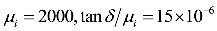 (@ 0.1 MHz),
 ) in the vicinity of a conducting rectangular loop. Ferrite cores or plates are often used to guide magnetic fields as H-field directors, but we use this ferrite plate as an H-field reflector to guide more H-field to each resonator in order to reduce H-field leakage. The position and the size of the ferrite plate are optimized using a genetic algorithm to push more H-field toward the opposite resonator and to improve power transmission efficiency. The size of the resonator is limited to
 . To match with the 50 Ω characteristic impedance of the feed cable at 13.56 MHz, an L-matching network using lumped LC elements is employed between the feed cable and the rectangular loop. The optimized resonators with the ferrite plates are built on a
  ground plate, and the transmission characteristics are measured using a network analyzer when the distance between the transmitter and the receiver is fixed at 50 cm. The measured results show the transmission efficiency of 6.25%, which is 4.2 dB higher than that of the resonators without ferrite plates.
2. Resonator Structure and Optimization
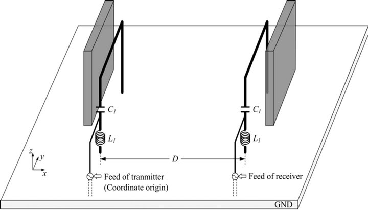
The objective of this research is to increase the power transmission efficiency of the resonator that operates at 13.56 MHz. Figure 1 shows the basic geometry of the proposed resonator, which consists of a rectangular loop, a ferrite plate, and a matching network. Two identical
 (a) Perspective view
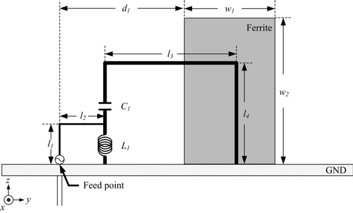 (b) Front view
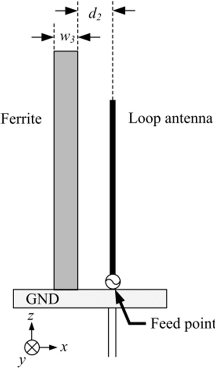 (c) Side view
Figure 1. Geometry of the proposed loop resonator with the ferrite plate.
resonators with dimensions of  are separated by 50 cm on a
  ground plate, as shown in Figure 1(a). The ferrite plate that has a surface area of
  with a thickness
  of 6.7 mm is located behind the rectangular loop by
 . When the ferrite plate is placed in the near field region with an appropriate distance
 , it can operate as an H-field reflector. This consequently enhances the H-field in a bore-sight direction and results in improved transmission efficiency for the resonator. An additional small loop
  with lumped elements of L1 and C1 are added in the rectangular loop
  to build an L-matching network as shown in Figure 1(b) to reduce the length of the loop and improve the matching characteristics.
To further increase the proposed resonator’s transmission efficiency, the detailed design parameters, such as the size of the loops , the size of the ferrite plate
 , locations
 , and lumped element values
 , were optimized using a genetic algorithm in conjunction with a fullwave electromagnetic simulator (FEKO Suite 5.5) [6,7]. In the genetic algorithm (GA) process, crossover and mutation are applied to create the next generation, each of which consists of 40 populations. A fitness function is used to evaluate each population to improve the matching characteristics and increase the transmitted power at 13.56 MHz, as defined in Equation (1).
 (1)
(1)
The optimized design parameters of the resonator are listed in Table 1, and the performance of the optimized design is discussed in the next section.
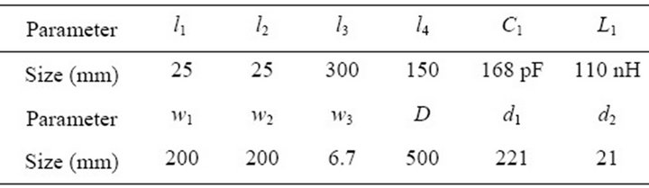
Table 1. Dimensions of the optimized resonator.
3. Measurement and Analysis
3.1. Measurement
Figure 2 shows the reflection coefficient and transmission efficiency of the optimized resonator. The power transmission efficiency was defined as the ratio of the transmitted power to the input power between two identical resonators. The measurement was conducted using an Agilent 8753D network analyzer in a semi-anechoic chamber. The results show a reflection coefficient of −16.8 dB and a power transmission efficiency of −12.3 dB at 13.56 MHz, which agree well with the simulation. We also examine the variation of the transmission efficiency by changing the distance D as shown in Figure 3, and the results show the power transmission efficiency of −9.7 dB and −29.9 dB at D = 30 cm and D = 100 cm, respectively. Figure 4 shows comparisons of the power transmission efficiency with the various plate materials. Styrofoam  FR4
FR4  copper
 , perfect magnetic conductor (PMC), and prefect electric conductor (PEC) are used as plate materials,
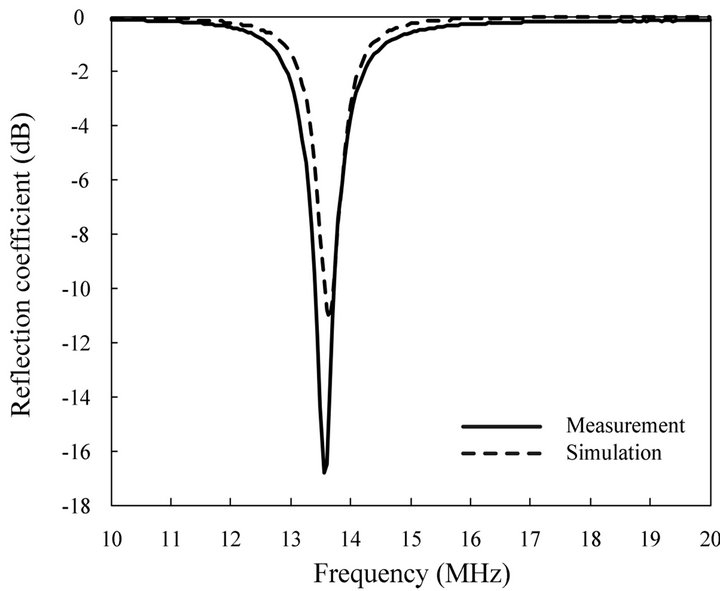 (a) Reflection coefficient
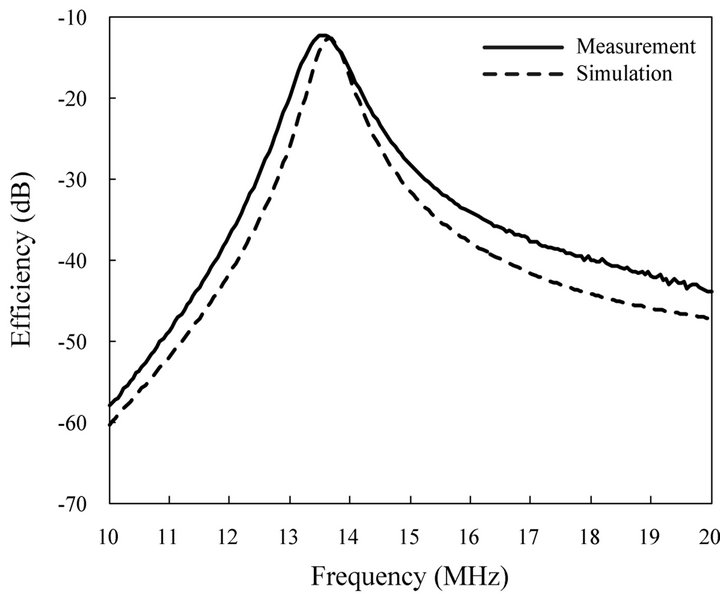 (b) Transmission efficiency
Figure 2. Performances of the proposed resonator.
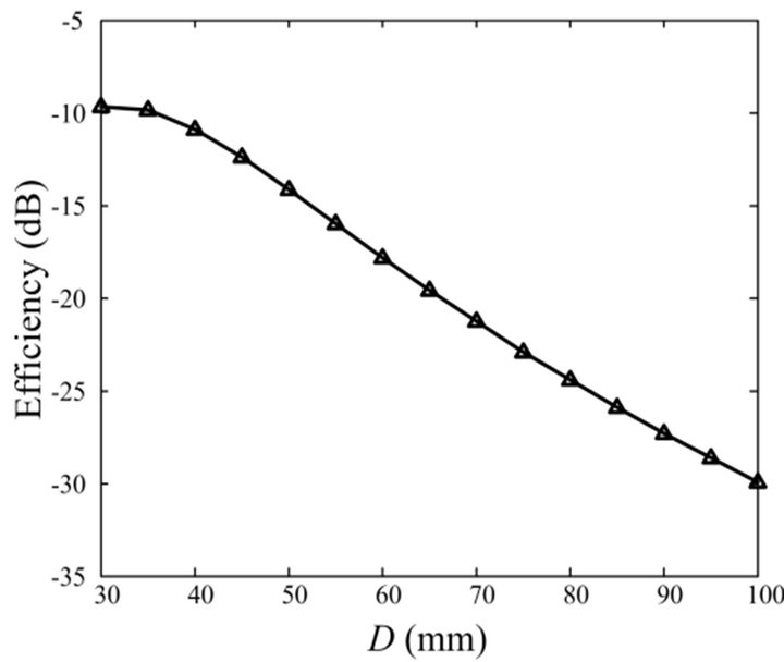
Figure 3. Transmission efficiency according to D.
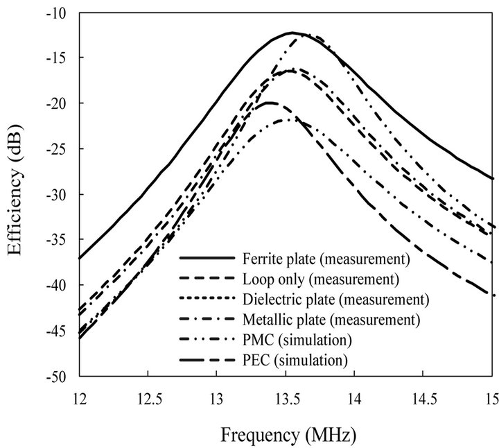
Figure4. Transmission efficiency according to plate materials.
and their power transmission efficiencies are −16.5 dB, −16.3 dB, −21.8 dB, −12.7 dB, and −21 dB, respectively. The results demonstrate that the power transmission efficiency can be improved more through the use of ferrite materials than other materials.
3.2. Analysis
To analyze how ferrites with high permeability improve the power transmission efficiency, we observe H-field distributions when currents flow through a wire placed along the z-axis. Figures 5(a)-(c) show the results in the presence of a PEC plate, a PMC plate, and a ferrite plate (thickness = 6.7 mm), respectively. As can be seen, only the tangential component of the H-field remains near the surface of the PEC plate. On the other hand, only the normal component exists in proximity to the PMC plate. Similar H-field distributions are observed in the case of the ferrite plate, which means that the normal component is dominant near the surface, as in the PMC plate [8].
To further examine how the optimized design achieves higher transmission efficiency with the ferrite, the Hfield strength is observed at three points while varying the ferrite position d1, as illustrated in Figure 6. The three observation points are given as ,
,  and
and  and the coordinate origin is the feed point of the transmitting resonator. As expected, the H-field strengths at P1 and P2 are maximized when the ferrite plate is located at its optimized position of
 . The resulting H-field strength at P2 is about 17.3 dB higher than that at P3, which explains the improvement of the power transmission efficiency of the proposed resonator.
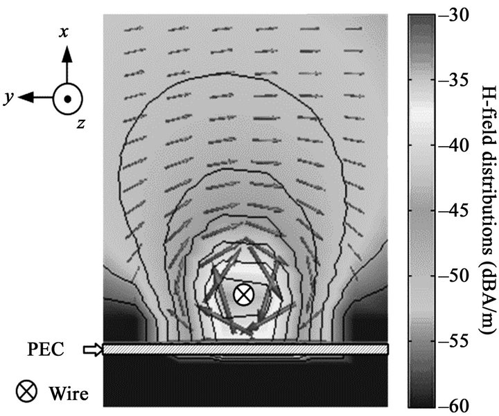 (a) PEC
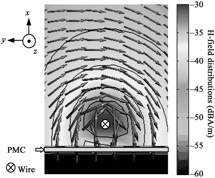 (b) PMC
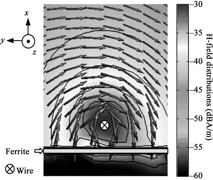 (c) Ferrite
Figure 5. H-field distributions according to the plate materials.
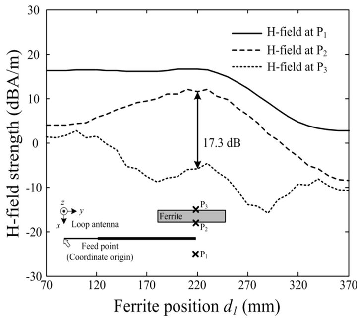
Figure 6. Variation of H-field strength according to ferrite plate positions.
4. Conclusion
We proposed a novel resonator to improve power transmission efficiency using a ferrite plate. The proposed resonator was composed of a rectangular loop, a ferrite plate, and a matching network. An additional small loop with lumped elements was added as an L-matching network in the rectangular loop to improve the matching characteristics. The H-field distributions were controlled by varying the size and the location of the ferrite plate, and then detailed parameters were optimized using a GA in conjunction with the FEKO EM simulator. To verify the suitability of the proposed resonator, the power transmission efficiency was measured in a semi-anechoic chamber, and its results were further compared with various materials for the plate. The results proved that the proposed resonator was capable of improving power transmission efficiency through the use of the ferrite plate and may be applied to wireless power transfer applications.
5. Acknowledgements
This research was supported by the MSIP (Ministry of Science, ICT & Future Planning), Korea, under the ITRC (Information Technology Research Center) support program (NIPA-2013-H0301-13-2007) supervised by the NIPA (National IT Industry Promotion Agency).
REFERENCES
- J. J. Hirai, T. W. Kim and A. Kawamura, “Wireless Transmission of Power and Information for Cableless Linear Motor Drive,” IEEE Transactions on Power Electron, Vol. 15, No. 1, 2000, pp. 21-27. doi:10.1109/63.817358
- A. Kurs, A. Karalis, R. Moffatt, J. D. Joannopoulos, P. Fisher and M. Soljačić, “Wireless Power Transfer via Strongly Coupled Magnetic Resonances,” Science, Vol. 317, No. 5834, 2007, pp. 83-86. doi:10.1126/science.1143254
- ANSI/IEEE C63.4, “American National Standard for Methods of Measurement of Radio-Noise Emissions from Low-Voltage Electrical and Electronic Equipment in the Range of 9 kHz to 40 GHz,” ANSI/IEEE C63.4, 2004, pp. 1-135.
- E. M. Thomas, J. D. Heebl, C. Pfeiffer and A. Grbic, “A Power Link Study of Wireless Non-Radiative Power Transfer Systems Using Resonant Shielded Loops,” IEEE Transactions on Circuits and Systems I, Vol. 59, No. 9, 2012, pp. 2125-2136. doi:10.1109/TCSI.2012.2185295
- A. Karalis, J. D. Joannopoulos, and M. Soljacic, “Efficient Wireless Non-Radiative Mid-Range Energy Transfer,” Annals of Physics, Vol. 323, No. 1, 2008, pp. 34-48. doi:10.1016/j.aop.2007.04.017
- EM Software and Systems, “FEKO Suite 5.5,” 2012. www.feko.info
- Y. Rahmat-Samii and E. Michielssen, “Electromagnetic Optimization by Genetic Algorithms,” Wiley, New York, 1999.
- I. Lindell and A. Sihvola, “Transformation Method for Problems Involving Perfect Electromagnetic Conductor (PEMC) Structures,” IEEE Transactions on Antennas and Propagation, Vol. 53, No. 9, 2005, pp. 3003-3011. doi:10.1109/TAP.2005.854519