Journal of Electromagnetic Analysis and Applications
Vol.4 No.9(2012), Article ID:22478,5 pages DOI:10.4236/jemaa.2012.49049
Impact of a Radio Frequency Electronic Article Surveillance (EAS) System on Active Implants*
![]()
Institute of Health Care Engineering with European Notified Body #0636 of Medical Devices, Graz University of Technology, Graz, Austria.
Email: norbert.leitgeb@tugraz.at
Received July 5th, 2012; revised August 6th, 2012; accepted August 17th, 2012
Keywords: Electromagnetic Compatibility; Cardiac Pacemaker; RFID; Electronic Article Surveillance; Health Risk
ABSTRACT
In view of the omnipresence of electronic article surveillance (EAS) systems in daily life and the increasing number of patients with active implants, there is concern about adverse electromagnetic interference in particular cardiac pacemakers (CPM) and cardioverter defibrillators (ICD), which due to sensing electrocardial signals are particularly vulnerable. To provide quantitative information interference of monopolar CPM and ICD by EAS systems operating at 8.2 MHz radiofrequency electromagnetic fields (EMF) investigations have been performed by exposing numerical anatomical models of pacemaker patients with implants at the conventional left or right pectoral sites and at the abdomen to magnetic fields of a simulated EAS gate source. Investigation of normal position in the centre and worst case with the back next to the gate showed that adverse interference such as inadequate sensing need not be expected at any position. This applies for conventional sensing thresholds even if the exposure span of existing EAS systems is taken into account. However, if full use is made of the newly expanded exposure budget, adverse interference cannot be excluded.
1. Introduction
Worldwide, electronic article surveillance systems (EAS) and personal identification systems (PIS) are widely used for a variety of purposes such as protecting against theft, object identification and access control, and passing through gates has become frequent in daily life. There are already several reports on measured magnetic fields (MF) and electromagnetic fields (EMF) indicating large differences among device’s emitted field amplitudes including excess of recommended reference levels [1-6].
In view of the omnipresence of EAD devices in daily life and the increasing number of patients with active implants there is concern about adverse electromagnetic interference in particular with implanted cardiac pacemakers (CPM) and cardioverter defibrillators (ICD). In fact, sensing cardiac activity makes CPM and ICD vulnerable to electromagnetic interference. Induced interference voltages may cause permanent functional changes or transient alteration in pacing and, hence, may pose health risks to patients. Reported interactions include asynchronous pacing, tachycardia, inhibited pacing and paced beats, in some patients causing symptoms such as palpitation or presyncope [7-11]. Therefore, concern about adverse electromagnetic interference with implanted CPM or ICD may be justified, in particular since the prevalence of pacemaker patients among the general population reached already about 0.8% of the general population [12].
To provide quantitative information the paper analyses interference of monopolar CPM and ICD by EAS gates operating at 8.2 MHz radiofrequency EMF. To allow conclusions independent from specific device models results are assessed with regard to technical EMF immunity requirements of electronic implants as defined in medical device safety standards.
2. Method
To investigate electromagnetic interference (EMI) with electromagnetic fields several numerical anatomical models of pacemaker patients were generated with the pacemaker can at different conventional implantation sites. To represent an average human the numerical model NORMAN has been chosen with a body mass index (BMI) of 23.6 which has been derived from series of magnetic resonance images (MRI) of an average European man (73 kg, 176 cm) with a spatial resolution of 2 × 2 × 2 mm voxels [13]. Its biologic tissues were segmented into 35 different types. Dielectric values of body tissues were taken from the literature [14]. To check for the influence of anatomical variability the anatomical model Visible Man of a Caucasian (103 kg, 186 cm, Visible Human Projekt® National Library of Medicine, Maryland) had been modified. It is separated into 31 different biologic tissues and represents an obese man with BMI 29.8.
Models of pacemaker patients were generated by numerically implanting a digital model of a cardiac pacemaker (Medtronic) into the anatomical models below the cutis at the conventional implantation sites (left pectoral, right pectoral and abdominal) (Figure 1) [12,15]. The electrically insulated monopolar electrode was placed at the ventricular apex via the vena cava and vena subclavia, respectively, pushed forward and finally contacted to the right ventricular apex. In abdominal position the can was placed similarly with the electrode inserted into the vena femoralis (Figure 1). To check for the influence of anatomical variability the model of an obese patient based on the anatomical Visible Man model, a Caucasian (103 kg, 186 cm), has also been investigated (Visible Human Projekt® National Library of Medicine, Maryland). It is separated into 31 different biologic tissues and represents an obese man with BMI 29.8.
The induced intracorporal electric field distribution was calculated with the commercial software package CST Studio® Suite 2009 (CST 2009) applying the Finite Integration Technique [16]. The interference voltage was determined by integrating the electric potential differrences between cardiac electrode tip and pacemaker can.
The numerical model of the EAS field source was generated to fit with measured field distributions of the EAS gate Nedap PG 30 (input power 12 W per antenna), operating at 8.2 MHz. The calculated field distribution of the numerical EAS model has been compared with measured field values by mimicking averaging over the 100 cm2 field probe sensing area. Electric currents in the numerical source model had been adjusted such as to achieve a least square fit with reported measurements [17]. The resulting field distribution of the simulated EAS gates together with the comparison with measured values is shown in Figure 2.
Investigations were performed with patient models placed at conventional position in the centre between the gates and in worst case position with the back in next to the gate. In addition, the worst case exposure, namely exposure to a homogeneous magnetic field oriented frontal to the body has been analysed for comparison.
3. Results
The interference peak-to-peak voltage (UPP) induced in the average human CPM patient NORMAN with left pectoral implantation at central position was UPP = 0.67 mVpp. In the worst case (back next to the gate) UPP increased by the 15fold to 10 mVpp. Results show that the site of CMP implantation counts. While a minor difference was found in right pectoral implantation (UPP = 11.3 mV) a 5.1fold lower interference voltage (1.96 mVpp)
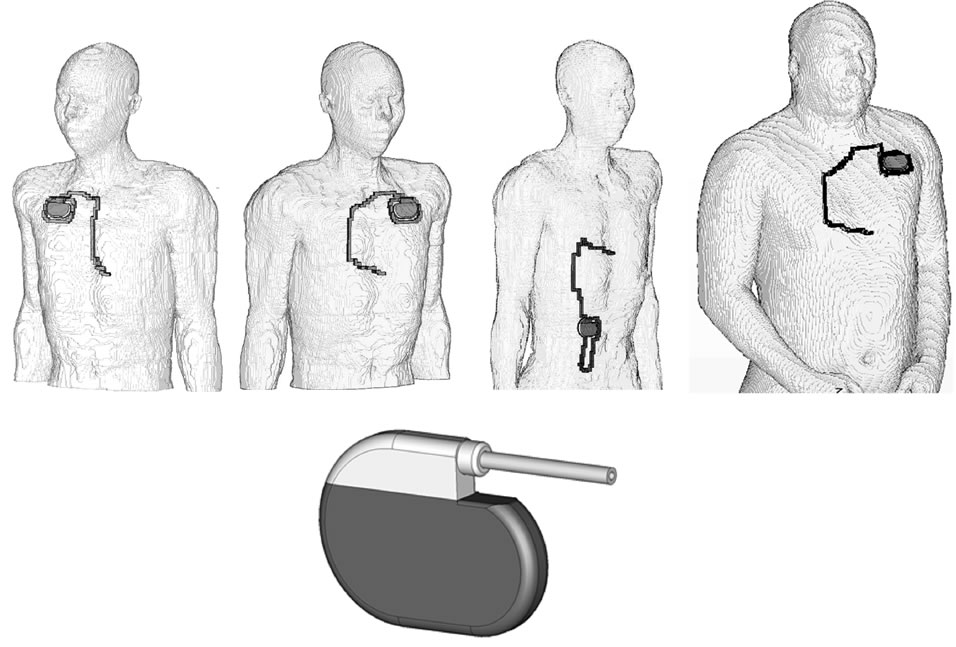
Figure 1. Numerical models of pacemaker patients with right pectoral (left), left pectoral (middle) and abdominal implantation, based on the modified model NORMAN, and the model of the cardiac pacemaker (below).
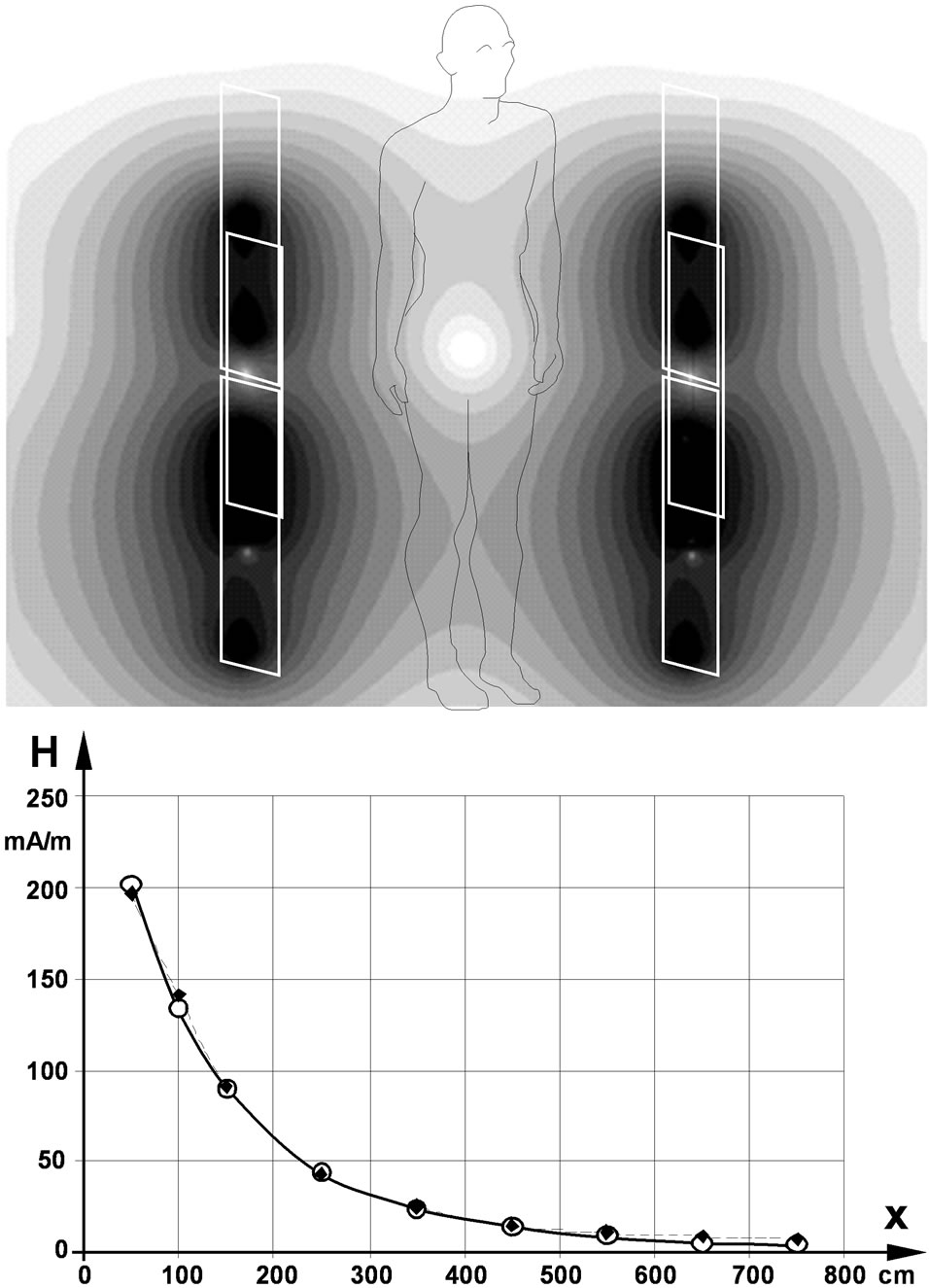
Figure 2. Distribution of the magnetic field of the walkthrough gates of an 8.2 MHz EAS device in the cross sectional plane (above) and along the x-axis in 1 m height (below); open circles…calculated values, full squares…measured values [17].
was encountered at abdominal implantation.
At the larger and obese pacemaker patient model in worst case position with its back next to the gate the interference voltage (UPP = 7.9 mVpp) was 21% lower compared to the NORMAN model.
The exposure to an 8.2 MHz homogeneous magnetic field with frontal orientation and a field strength equal to the central value of the EAS gate resulted in 8 mVpp while scaling with the higher value at the gate resulted in 369 mVpp. While these results are gained from a specific device, they can be used to conclude on the group of similar devices. The published data of EAS devices operating at about 8 MHz revealed a span of measured maximum values ranging from 80 - 330 mA/m [1,3,6], which goes 63% beyond the maximum magnetic field strength value 203 mA/m of the investigated particular device and elevates the worst case interference voltage to 18.4 mVpp which is still 445 fold below the immunity level.
Existing EAS devices exceed the former reference value (89 mA/m) by up to 3.7 fold but still remains below actual ICNIRP’s reference level 21 A/m [18] However, the revised recommendation allows elevating the magnetic field strength of EAS. If this would be done at the centre of the EAS gates, induced interference voltages would increase to 3.2 Vpp in normal position and to 48 Vpp in worst case position with the back next to the gate. Homogeneous field exposure at reference level would induce an interference voltage of 38 Vpp.
4. Discussion
General EMC requirements for electronic implants are laid down in their generic standard [19] which at 8.2 MHz requires immunity up to 1.83 A/m magnetic field strength. Since measured maxima of existing EAS are well below this level, in general adverse interference should not be expected. However, specific devices such as CPM and ICD may be particularly vulnerable to EMF.
To assess the health risk of patients with such implants, the computed interference voltages are compared with EMC requirements of safety standards for cardiac pacemakers [20] and for cardioverter defibrillators [21,22]. These standards require devices shall exhibit minimum immunity to electromagnetic interference which they define as “any harm caused by a device’s susceptibility to electric and/or electromagnetic influences, in particular any device malfunction persisting after exposure” [20, 21].
Cardiac sensing makes CPM and ICD vulnerable to interference signals because they might be confused with cardiac activity and subsequently cause inadequate pacing. Since in addition the devices must not be permanently damaged by much stronger impact of electric fields induced by external defibrillation, only transient effects might occur if CPM and ICD devices confuse interference signals with cardiac activity. This results in inappropriate sensing and subsequent inadequate pacing (inhibition or acceleration, respectively).
Usually a wide variety of different types of implantable CPM and ICD is used, with different settings of their electrocardial sensing threshold. Protection from sensing interference signals is tested with a test signal which in the particular EAS case is a 8.2 MHz carrier frequency modulated with 100 ms 130 Hz bursts repeated with 1.4 Hz (according to a heart rate of 84 bpm). CPM and ICD shall be immune to test signal amplitudes up to 8.2 Vpp if their sensing threshold is set to 2 mVpp. However, it cannot be excluded that in rare cases with severe cardiac disorder the sensing threshold might be decreased up to about 7 fold e.g. if cardiac signals are unusual low or in case of unfavourable atrial lead position. However, it is acknowledged that this is a tradeoff since this increases also the risk of adverse biosignal sensing such as myopotentials [20].
Compared to the levels of immunity to RF EMF required in safety standards of CPM and ICD it can be concluded that in general pacemaker patients are not at risk from existing EAS devices operating at 8.2 MHz since even in worst cases induced interference voltages remain 8.4 fold below the required immunity level. Since the anatomical variance in terms of increasing the induction loop area from the actual 150 cm2 to the maximum 400 cm2 (2.7 fold) the safety margin is large enough to allow concluding that even for worst case position and maximum induction areas adverse interference with CPM and ICD need not be expected if implants meet actual EMC requirements. Although reducing sensing thresholds by 3 fold would still acceptable, the safety margin does not cover the whole possible range.
It could be argued that the conclusion might hold for new devices but not for older ones. In fact, the first CPM safety standard dates back to 1983 and did not contain specific EMC requirements. This did not change with the second edition in 1988 [23]. Only in 1997 the European generic standard of electronic implants contained the first EMC requirements which at 8.2 MHz required immunity up to 1.83 A/m while no agreement could be reached at international level. Since 2003 the actual version of the CPM standard is redefining EMC requirements which supersede those of the generic standard. Apart from adverse events such as breakage or dislocation of electrodes CPM lifetime depends on battery consumption. Statistics shows that 36% of the devices stand up to 8 years, added by another 54% standing 8 - 12 years and 10% longer than 12 years [24]. However, since at the time of implantation 42% of the patients are older than 80 years the average use time of implanted CPM should be less than 9 years. Consequently, it is justified basing conclusions on actual EMC requirements. This is confirmed by the literature which found no interaction of RF EAS with any CPM [10].
However, if full use is made of the new extended exposure budget [18] compared to the former one [23], adverse sensing should be expected in worst case position and even in normal position in case of reduced sensing thresholds.
5. Conclusion
Existing EAS gates operating at 8.2 MHz will not exhibit adverse interference with implanted CPM and ICD devices compliant with existing particular safety standards. Only in hypothetical cases with sensing thresholds adjusted to a minimum and/or critically not compliant devices interference cannot be absolutely ruled out. However, if full use of the new exposure budget is made, adverse sensing should be expected. Due to different exposure conditions and immunity levels this conclusion cannot be extrapolated to EAS systems operating at other frequencies.
REFERENCES
- J. H. Bernhardt, A. F. McKinlay, R. Matthes, et al., “Possible Health Risk to the General Public from the Use of Security and Similar Devices,” International Commission on Non-Ionizing Radiation Protection, Munic, 2002.
- W. Boivin, J. Coletta and L. Kerr, “Characterization of the Magnetic Fields around Walk-Through and HandHeld Metal Detectors,” Health Physics, Vol. 84, No. 5, 2003, pp. 582-593. doi:10.1097/00004032-200305000-00003
- C. Harris, W. Boivin, S. Boyd, J. Coletta, L. Kerr, K. Kempa and S. Aronoiw, “Electromagnetic Field Strength Levels Surrounding Electronic Article Surveillance (EAS) Systems,” Health Physics, Vol. 78, No. 1, 2000, pp. 21- 27. doi:10.1097/00004032-200001000-00005
- M. Martinéz-Búrdalo, A. Sanchis, A. Matín and R. Villar, “Comparison of SAR and Induced Current Densities in Adults and Children Exposed to Electromagnetic Fields from Electronic Article Surveillance Devices,” Physics in Medicine and Biology, Vol. 55, No. 4, 2010, pp. 1041- 1055. doi:10.1088/0031-9155/55/4/009
- G. Neubauer, H. Molla-Djaffari, K. D. Pühringer, H. Garn, N. Winkler, H. Preiß and G. Schmid, “Measurement and Safety Assessment of Electromagentic Fields around Anti-Theft Devices (German),” AUVA Report #23,Vienna, 1998.
- J. Trulsson, G. Anger and U. Estenberg, “Assessment of Magnetic Fields Surrounding Electronic Article Surveillance Systems in Sweden,” Bioelectromagnetics, Vol. 28, No. 8, 2007, pp. 664-666. doi:10.1002/bem.20359
- S. J. Seidman, R. Brockman, B. M. Lewis, J. Guag, M. J. Shein, W. J. Clement, J. Kippola, D. Digby, C. Barber and D. Huntwork, “In Vitro Tests Reveqal Sample Radiofrequency Identification Readers Inducing Clinically Significant Electgromagnetic Interference to Implantable Pacemakers and Implantable Cardioverter-Defibrillators,” Heart Rhythm, Vol. 7, No. 1, 2010, pp. 99-107. doi:10.1016/j.hrthm.2009.09.071
- W. Irnich, “Electronic Security Systems and Active Implantable Medical Devices,” Pacing and Clinical Electrophysiology, Vol. 25, No. 8, 2002, pp. 1235-1258. doi:10.1046/j.1460-9592.2002.01235.x
- R. Frank, “Behaviour of 20 Pacemakers as Patients Pass through 2 Models of Theft-Detection Doors (French),” Annales de Cardiologie et d’Angeiologie, Vol. 49, No. 3, 2000, pp. 187-197.
- M. E. McIvor, J. Reddinger, E. Floden and R. C. Sheppard, “Study of Pacemaker and Implantable Cardioverter Defibrillator Triggering by Electronic Article Surveillance Devices (SPICED TEAS),” Pacing and Clinical Electrophysiology, Vol. 21, No. 10, 1998, pp. 1847-1861. doi:10.1111/j.1540-8159.1998.tb00002.x
- J. Mugica, L. Henry and H. Podeur, “Study of Interactions between Permanent Pacemakers and Electronic Antitheft Surveillance Systems,” Pacing and Clinical Electrophysiology, Vol. 23, No. 3, 2000, pp. 333-337.
- N. Leitgeb, F. Niedermayr, R. Neubauer and G. Loos, “Risk of Pacemaker Patients by TASER X26 Contact Mode Application,” Journal of Electromagnetic Analysis and Application, Vol. 4, No. 2, 2012, pp. 96-100.
- P. J. Dimbylow, “FDTD Calculations of the Whole Body Averaged SAR in an Anatomically Realistic Voxel Model of the Human Body from 1 MHz to 1 GHz,” Physics in Medicine and Biology, Vol. 42, No. 3, 1997, pp. 479-490. doi:10.1088/0031-9155/42/3/003
- S. R. Gabriel, W. Lau and C. Gabriel, “The Dielectric Properties of Biologic Tissues: Measurement in the Frequency Range 10 Hz - 20 GHz,” Physics in Medicine and Biology, Vol. 41, No. 11, 1996, pp. 2251-2269. doi:10.1088/0031-9155/41/11/002
- N. Leitgeb, F. Niedermayr, R. Neubauer and G. Loos, “Interference of Implanted Cardiac Pacemakers with TASER X26 Dart Mode Application,” Biomedical Engineering, Vol. 57, No. 3, 2012, pp. 201-206. doi:10.1515/bmt-2012-0002
- T. Weiland, “A Method for Discretically Solving Maxwell’s Equations for Six-Component Fields (German),” International Journal of Electronics and Communications, Vol. 31, 1977, pp. 16-120.
- U. Estenberg, G. Anger and J. Trulsson, “Mapping of Magnetic Fields Surrounding EAS and RFID Systems,” SSI Rapport #3, Stockholm, 2006.
- International Commission on Non-Ionizing Radiation Pro- tection, “Guidelines for Limiting Exposure to Time-Varying Electric and Magnetic Fields (11 Hz to 100 kHz),” Health Physics, Vol. 99, No. 6, 2010, pp. 818-836.
- European Standards, “EN 45502-1. Active Implantable Medical Devices. Part 1: General Requirements for Safety, Marking and Information to be Provided by the Manufacturer,” 1997.
- European Standards, “EN 45502-2-1. Active Implantable Medical Devices. Part 2-1: Particular Requirements for Active Implantable Medical Devices Intended to Treat Bradyarrhythmia (Cardiac Pacemakers),” 2003.
- European Standards, “EN 45502-2-2. Active Implantable Medical Devices. Part 2-1: Particular Requirements for Active Implantable Medical Devices Intended to Treat Tachyarrhythmia (Includes Implantable Defibrillators),” 2003.
- American National Standards Institute/Association for the Advancement of Medical Instrumentation PC69, “Active Implantable Medical Devices—Electromagnetic Compatibility—EMC Test Protocols for Implantable Cardiac Pacemakers and Implantable Cardioverter Defibrillators,” 2007.
- International Commission on Non-Ionizing Radiation Protection, “Guidelines for Limiting Exposure to Time-Varying Electric, Magnetic and Electromagnetic Fields (up to 300 GHz),” Health Physics, Vol. 74, No. 4, 1998, pp. 494- 522.
- A. Markewitz, “Annual Report on the German Cardiac Pacemaker Register,” 2009. http://www.pacemakerregister.de
NOTES
*The authors declare no conflict of interest.