Journal of Electromagnetic Analysis and Applications
Vol.4 No.6(2012), Article ID:20339,5 pages DOI:10.4236/jemaa.2012.46032
Rectangular Microstrip Antenna for Symmetrical 3-D Beam Widths for an Efficient Feed of Reflector Antenna and Its Quantitative Analysis
![]()
Department of ECE, Siliguri Institute of Technology, Siliguri, Darjeeling, India.
Email: piyalirekha@yahoo.com
Received April 12th, 2012; revised May 13th, 2012; accepted May 22nd, 2012
Keywords: Air Substrate; Rectangular Microstrip Antenna; Symmetrical Beam widths
ABSTRACT
A simple rectangular microstrip antenna on low dielectric constant substrate such as air for improved radiation beam performance is theoretically investigated. The conventional patch antenna fabricated on common substrates always produces quite broader E plane pattern compared to its H plane. In the present investigation, the same microstrip antenna is designed on air substrate with a view to develop an efficient feed for parabolic reflector antenna, which shows an excellent radiation pattern with symmetrical 3 dB beam widths at its both E and H plane. The present antenna is compared with conventional structure to show its excellence in the beam performance is presented. The complete quantitative analysis to explore such radiation beam characteristics for both the structures (conventional and the present one) is also presented in this paper. An easy and handful relationship between the length of patch antenna and its fringing length for different types of substrate is established in the background of 3 dB beam widths. The proposed idea has been verified through a commercial software package for a patch operating in X band and a concrete physical insight into the phenomenon is developed.
1. Introduction
The conventional rectangular microstrip antenna is the most common geometry amongst the printed antennas etched on conventional poly tetra fluoride ethylene substrate with dielectric constant εr = 2.2 to 10.2 [1,2]. But the same microstrip antenna with simple air substrate is a least investigated configuration in any open literature, though it shows some interesting features particularly in its radiation characteristics.
Rectangular microstrip normally radiates linearly polarized wave with about 5 dBi gain. These patches radiate along the broadside direction with a non-uniform radiation beams where the E-plane pattern is always wider than that in H-plane [3]. As the microstrip antenna is inherently a low gain antenna, larger gain is always desirable. This gain of such antenna on conventional substrate can be enhanced by increasing its width-to-length ratio as is reported in [4]. But, as soon as the conventional substrate is replaced by air, gain of the antenna increases satisfactorily and the same thing has been achieved earlier, e.g. in [5]. Some researchers had employed different configurations like, wedge-shaped air dielectric [6] or micromachined air cavities in LTCC substrate [7] for different applications. One very recently reported work shows that the gain can be enhanced with improved front to back radiation ratio by creating an air cavity within the substrate [8]. But only a few handful investigations dealt with microstrip patch on air substrate, either theoretically or experimentally.
Improved gain for microstrip antenna is always desirable but along with this symmetrical or uniform radiation beam pattern in both the E and H plane is also requisite for using it as an efficient feed for a parabolic reflector or to cover a wide area, particularly for wireless communications. Microstrip antenna with such uniform 3 dB beam widths in both principal planes in fact, helps to illuminate the reflector antenna aperture which in tern reduces the tapering of field intensity near the edge of reflector surface and hence the gain of reflector can be increased.
Keeping this in view, we have executed comparative investigations theoretically using both air and conventional PTFE substrates (εr = 2.33) for two identical rectangular patches. The fact of uniform 3 dB beam widths in both E and H plane, replacing PTFE by air, is easy to observe either doing experiments or from simulated results, but without having any information indicating the reason. But in here, we have analyzed the beam width characteristics in both principal planes quantitatively. In the first section of this paper, the proposed idea is implemented and symmetrical 3-D beam width is observed. The results for the gain and beam widths compared to conventional antenna is discussed in section 3. In the next section of the paper, a quantitative analysis is presented to explain the symmetry in the beam widths for both E and H planes. A concrete mathematical background behind such behavior is presented in section 4. The analysis is based on the effective dimensions of the antenna in its E and H planes for both the conventional and present antenna. An easy and handful relationship between the length of patch antenna and its fringing length for different types of substrate is established in the background of 3 dB beam widths. The theory is successfully utilized to evaluate the causes for uniform 3 dB beam widths which is verified using [9] and close agreement is revealed.
2. Antenna Geometry
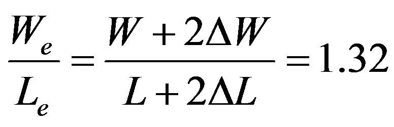
A rectangular microstrip antenna with length L = 12 mm and width W = 18 mm is shown in Figure 1 (top-view of the patch and side view of whole antenna structure). A dielectric substrate of thickness h =1.575 mm and relative permittivity of εr = 1 (air) or 2.33 (PTFE) is sandwiched between the patch and ground plane. When this antenna is radiating, its effective dimensions become Le = L + 2ΔL and We = W + 2ΔW; where ΔL and ΔW are fringing lengths and widths in each side.
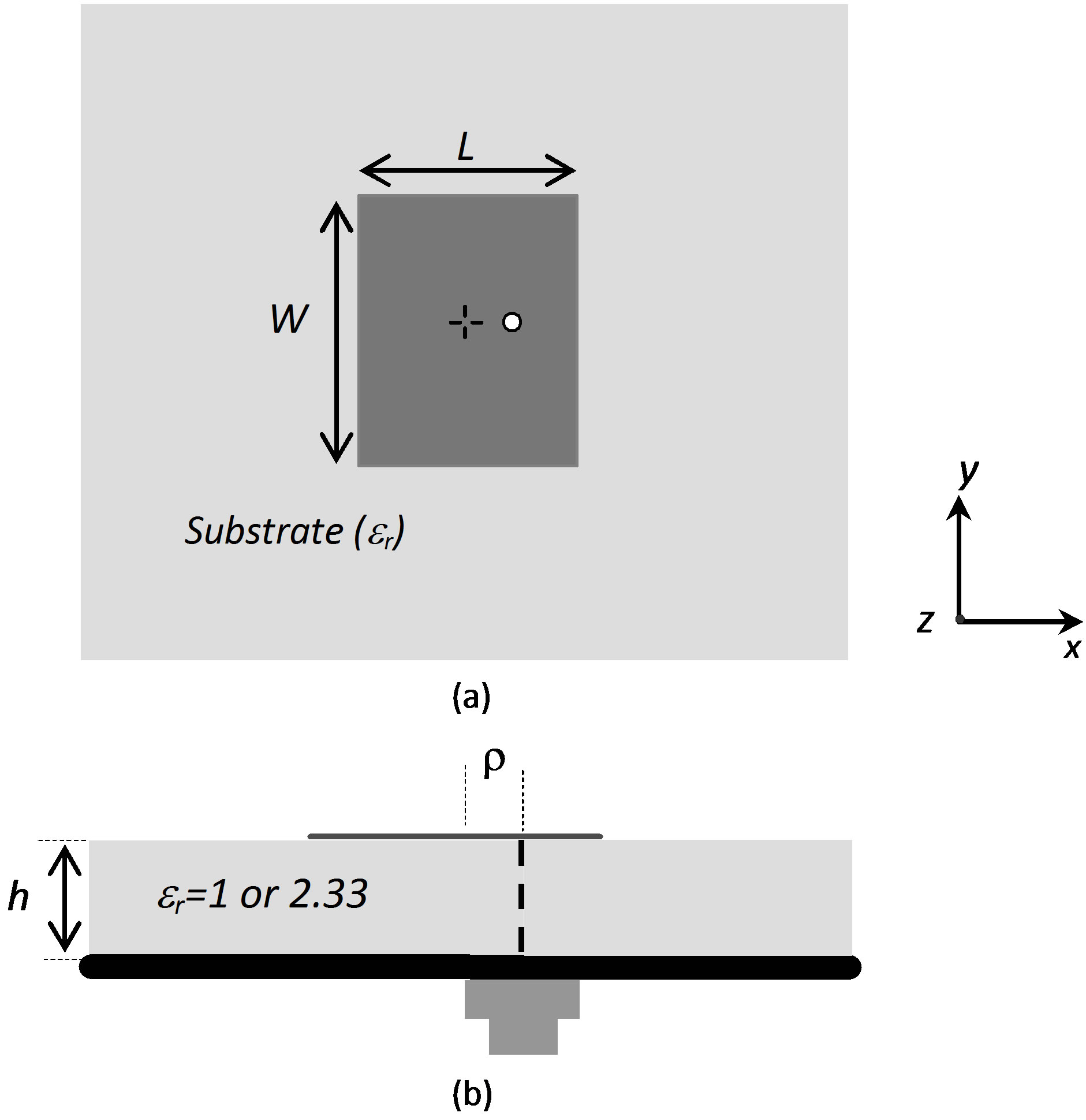
Figure 1. Schematic diagram of simple rectangular patch (a) Top view; (b) side view.
3. Results and Discussions
Simulated results obtained using [9] for the antenna with air substrate and the same with conventional PTFE substrate operating around X band is presented.
Figure 2 shows the complete return loss profile of the conventional antenna and also compared with the present one. It shows that both the antennas are properly fed to excite. It shows that as soon as PTFE substrate is replaced by air, the operating frequency shifts to the higher side of the spectrum. This shift in operating frequency may be attributed to the gain enhancing feature of such antenna with air or any other low dielectric constant substrate. The next step is to examine the radiation pattern for two identical antennas; one with conventional PTFE substrate and the other with air substrate. Therefore, the radiation patterns are compared between the antennas separately at E and H plane as shown in Figure 3. It is evident from the figure that, E plane 3 dB beam width is doubled than H plane beam width for conventional antenna with PTFE substrate while, those for same antenna with air substrate show no changes in beam widths between its E and H planes. Along with this the gain of this present antenna with air substrate is greater than conventional structure as expected [10]. The total results are summarized in Table 1.
Following the design guidelines [11]; the fringing lengths and widths (ΔL and ΔW), the effective lengths and widths along with the theoretical value of the antenna length using our theory has been calculated and presented in Table 2. It is seen that, fringing length ΔL for the present antenna with air substrate is 1.99 mm, where as that for antenna with conventional substrate is only 1.27. This result in fact creates a theoretical background for such beam width characteristics for both the antennas that are presented in the following section.
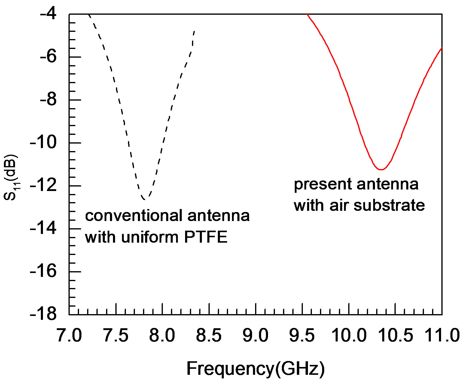
Figure 2. Return loss characteristics of a rectangular patch using different substrates. L = 12 mm, W = 18 mm, h = 1.575 mm, r = 2.6 mm; Substrates: uniform PTFE: εr = 2.33, uniform air: εr = 1.
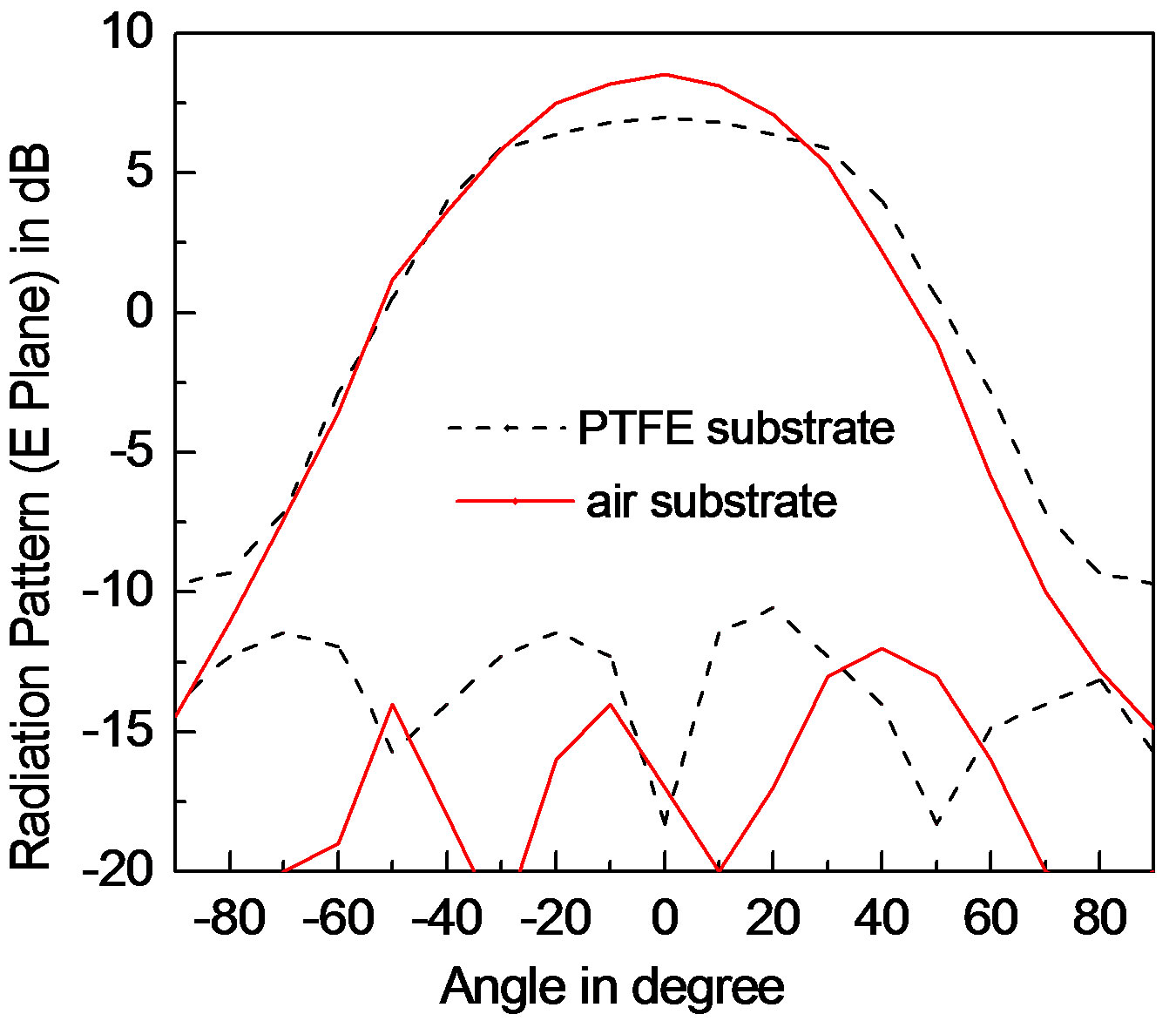
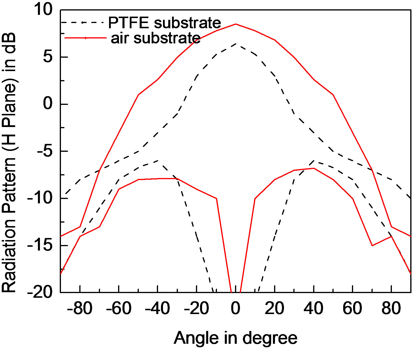
Figure 3. Radiation pattern of present antenna operating at 10.35 GHz compared with a conventional patch antenna operating at 7.90 GHz.
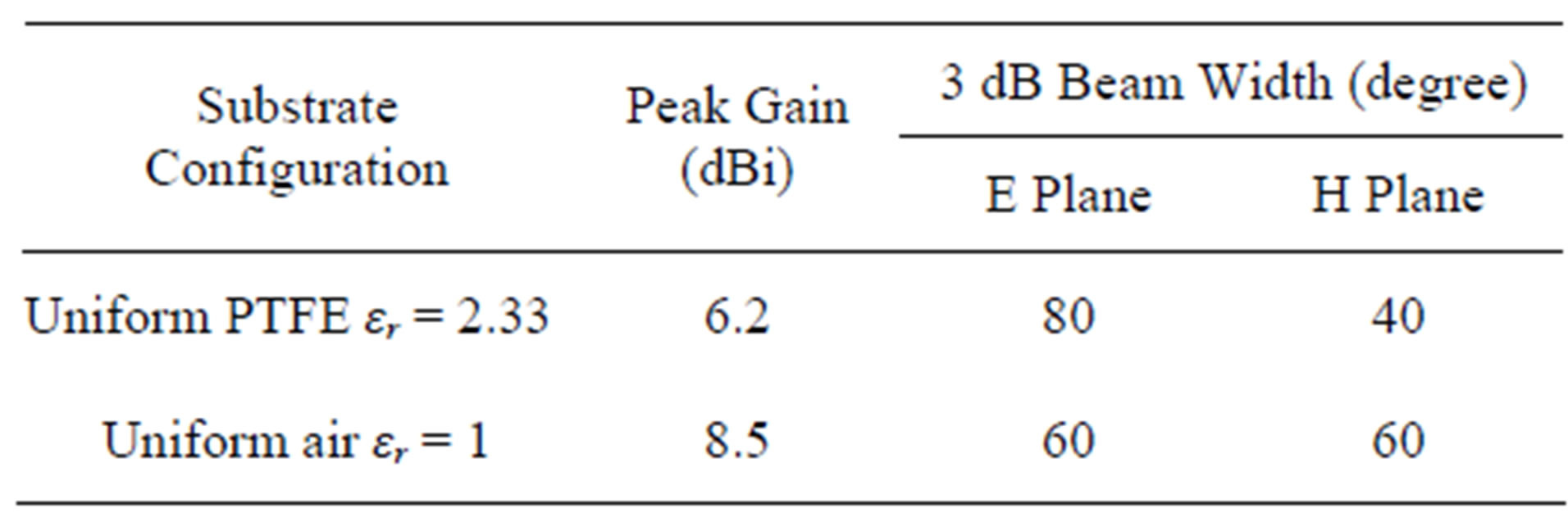
Table 1. Gain and beamwidth of rectangular microstrip antennas with different substrate configurations. Parameters as in Figure 2.
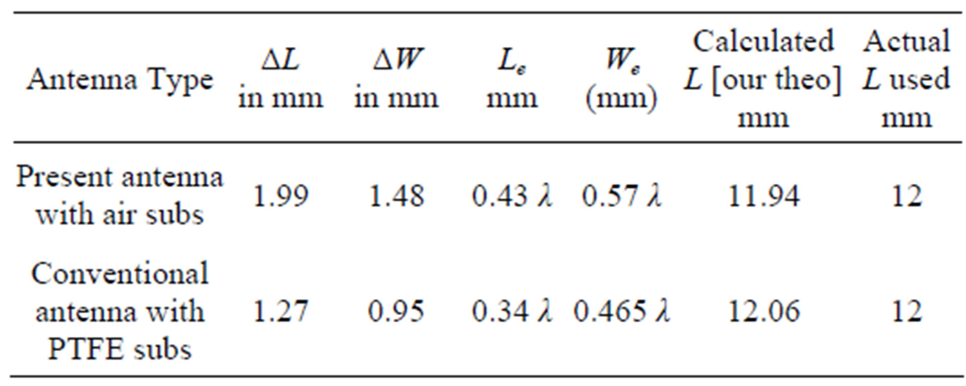
Table 2. Fringing lengths along length and width and effective dimensions of rectangular microstrip antennas with different substrate configurations. Parameters as in Figure 2.
4. Background Theory and Validation
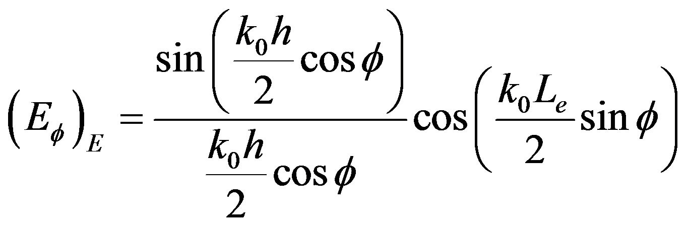
Any rectangular patch antenna radiates along its broadside direction and its field patterns at both E and H planes are given by [3,12] as
 (1)
(1)
for E Plane and
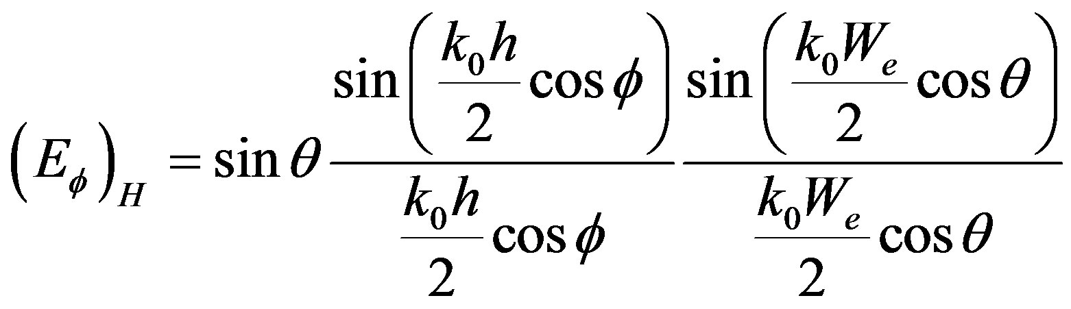 (2)
(2)
for H Plane.
As the antenna should have very small thickness (h) with respect to its operating wavelength (λ), we may assume, ; where
Thus the beam width in E plane is mainly governed by the second term of the Equation (1) as the first term approaches 1. This yield, at 3 dB point when ;
;
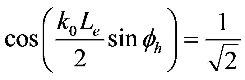 (3)
(3)
 (4)
(4)
 (5)
(5)
 (6)
(6)
Thus the half power beam width in E plane
 (7)
(7)
When we consider for H plane, the second term of the Equation (2) is not important for the same reason as discussed for E plane. The variation of third term of Equation (2) is rapid compared to the 1st term “sinθ” as We > λ and hence the main lobe in H plane is strictly governed by the third term of the equation [12]. Therefore to compute the half power beam width for H plane we may write at ,
,
 (8)
(8)
Hence,
and
 (9)
(9)
Thus the half power beam width in H plane
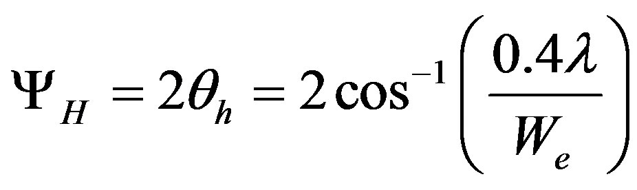 (10)
(10)
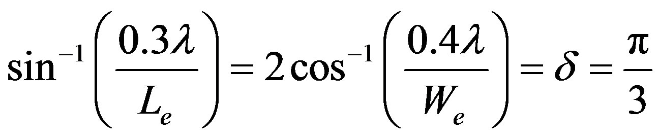
For beam width to be equal for both the planes
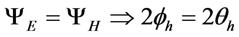 (11)
(11)
 (12)
(12)
If half of each term is equal to δ; then this equation is satisfied, if
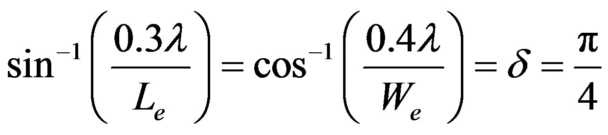 (12a)
(12a)
Hence,
 (12b)
(12b)
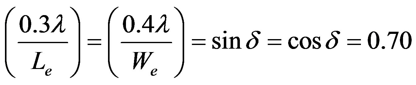
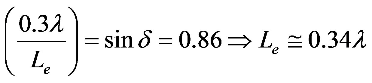
Thus,
 (13)
(13)
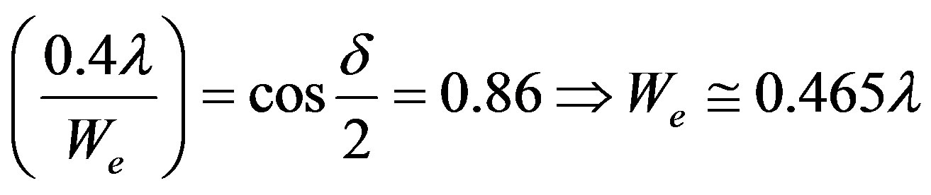
and
 (14)
(14)
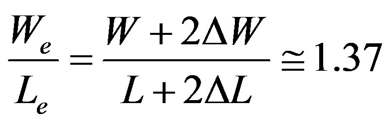
Thus the ratio,
 (15)
(15)
 (16)
(16)
Now from [13];
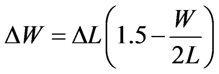 (17)
(17)
As, W/L = 1.5 for present case;

Thus,
 (18)
(18)
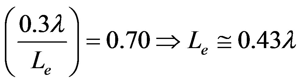
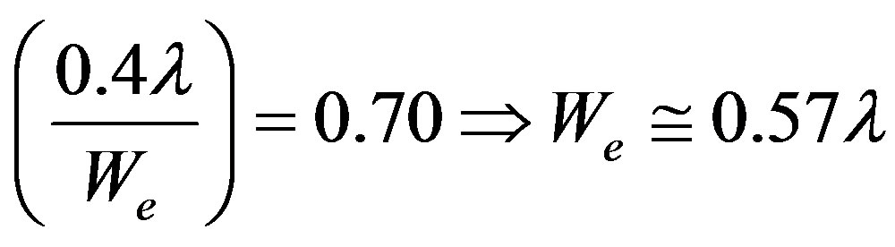
So,
 (19)
(19)
And this is satisfied for the present antenna on air substrate with L = 12 mm and ΔL = 1.99 mm as evident from Table 2.
On the other hand, if the same antenna is fabricated on conventional PTFE substrate, it is found that the beam width in E plane is just doubled than that at H plane. For that case of conventional antenna,
 (20)
(20)
 (21)
(21)
 (22)
(22)
If half of each term is equal to δ; then this equation is satisfied, if
Hence,
 (23)
(23)
and,
 (24)
(24)
Thus the ratio,
 (25)
(25)
 (26)
(26)
As, W/L = 1.5 for conventional antenna also;

Thus,
 (27)
(27)
So,
 (28)
(28)
Which is exactly the case with conventional antenna on uniform PTFE substrate with L = 12 mm and ΔL = 1.27 mm as revealed from same Table 2.
Thus an excellent agreement between the theoretical L, calculated using our theory and the actual L, which is used for the present investigation with different types of substrate is exposed, which corroborate the validity of the present analysis.
5. Conclusion
A rectangular microstrip antenna with low dielectric constant substrate (air) has been proposed for an efficient feed of a parabolic reflector antenna and the proposed idea has been verified thoroughly using quantitative analysis in the context of half power beam widths. A straightforward handful relationship between the length of patch antenna and its fringing length is established. The quantitative analysis that has been presented in the paper will surely be helpful for the scientists, researchers and practicing engineers looking for such low profile antenna with symmetrical beam radiation pattern. The thorough mathematical analysis for beam widths in relation to the effective dimension of the patch is very supportive for future investigations in this area.
REFERENCES
- L. j. Le and Z. r. Hu, “A Wideband Linear U-Slot Microstrip Patch Antenna Array for Wireless Application,” International Journal of Electronics, Vol. 96, No. 7, 2009, pp. 755-765. doi:10.1080/00207210902802848
- M. T. Islam, M. N. Shakib, N. Misran and T. S. Sun, “Broadband Microstrip Patch Antenna,” European Journal of Scientific Research, Vol. 27, No. 2, 2009, pp. 174- 180.
- R. Garg, P. Bhartia, I. Bahl and A. Ittipiboon, “Microstrip Antenna Design Handbook,” Artech House, Norwood, 2001.
- S. M. D. Abbas, S. Paul, J. Sen, P. R. Gupta, K. Malakar, S. Chattopadhyay and S. Banerjee, “Aspect Ratio: A Major Controlling Factor of Radiation Characteristics of Microstrip Antenna,” Journal of Electromagnetic Analysis and Applications, Vol. 3, No. 11, 2011, pp. 452-457. doi:10.4236/jemaa.2011.311072
- Y. T. Liu, C. W. Su, K. L. Wong and H. T. Chen, “An Air Substrate Narrow Patch Microstrip Antenna with Radiation Performance for 2.4 GHz WLAN Access Point,” Microwave and Optical Technology Letters, Vol. 43, No. 3, 2004, pp. 189-192. doi:10.1002/mop.20416
- F. W. Yao, S. S. Zhong and X. L. Liang, “Ultra-broadband Patch Antenna Using a Wedge-Shaped Air Substrate,” Asia-Pacific Microwave Conference, Suzhou, 4-7 December 2005, p. 3. doi:10.1109/APMC.2005.1606896
- M. Komulainen, et al., “Embedded Air Cavity Backed Microstrip Antenna on an LTCC Substrate,” Journal of European Ceramic Society, Vol. 27, No. 8-9, 2007, pp. 2881-2885. doi:10.1016/j.jeurceramsoc.2006.11.012
- K. Malakar, J. Nandi, S. Mitra, P. K. Gorai, S. Chattopadhyay and S. Banerjee, “Rectangular Microstrip Antenna with Air Cavity for High Gain and Improved Front to Back Ratio,” Journal of Electromagnetic Analysis and Applications, Vol. 3, No. 9, 2011, pp. 368-372. doi:10.4236/jemaa.2011.39058
- High Frequency Structure Simulator, HFSS v10, Ansoft Corp., Pittsburgh.
- S. Chattopadhyay, J. Y. Siddiqui and D. Guha, “Rectangular Microstrip Patch on a Composite Dielectric Substrate for High Gain Wide Beam Radiation Patterns,” IEEE Transactions on Antennas and Propagation, Vol. 57, No. 10, 2009, pp. 3324-3327. doi:10.1109/TAP.2009.2029607
- S. Chattopadhyay, M. Biswas, J. Y. Siddiqui and D. Guha, “Rectangular microstrip with Variable Air Gap and varying aspect Ratio: Improved formulations and experiments,” Microwave and Optical Technology Letters, Vol. 51, No. 1, 2009, pp. 169-173. doi:10.1002/mop.24025
- C. A. Balanis, “Antenna Theory: Analysis and Design,” 2nd Edition, John Wiley & Sons Inc., New York, 2001.
- S. Chattopadhyay, M. Biswas, J. Y. Siddiqui and D. Guha, “Input impedance of Probe Fed Rectangular Microstrip Antenna with Variable Air Gap and Varying Aspect Ratio,” IET Microwaves, Antenna and Propagation, Vol. 3, No. 8, 2009, pp. 1151-1156. doi:10.1049/iet-map.2008.0320