Journal of Electromagnetic Analysis and Applications
Vol.4 No.3(2012), Article ID:18225,4 pages DOI:10.4236/jemaa.2012.43014
A Novel Frequency Selective Surface with Improved Miniaturization Performance
![]()
1Department of Microwave Engineering, Harbin Institute of Technology, Harbin, China; 2Department of Electrical Engineering, The Fu Foundation School of Engineering and Applied Science, Columbia University, New York, USA.
Email: liwanluhit@gmail.com
Received January 23rd, 2012; revised February 20th, 2012; accepted February 28th, 2012
Keywords: Frequency Selective Surface (FSS); Miniaturization; Stability
ABSTRACT
Based on previous work, a novel Frequency Selective Surface (FSS) consisting of two metallic layers is proposed. The first layer is inductive-designed to generate the band-pass performance, while the second layer is capacitive-designed so that the miniaturization characteristic can be further improved. As a result, compared with the traditional single-layer structure, the profile of the FSS proposed is relatively small with the cell’s dimension only 0.0814λ × 0.0814λ. Moreover, the structure’s stability corresponding to waves of different polarizations and incident angles are also testified, which ensures the practicability of the proposed structure.
1. Introduction
Frequency selective surface (FSS) has been the subject of intensive investigation for its widespread applications as spatial microwave and optical filters for more than four decades [1-4]. It can be used in various applications, such as sub-reflectors of the frequency reuse system, band-pass radomes for radar cross-section (RCS) controlling, etc. [5-7].
The shape and dimension as well as the substrate characteristics determine the performance of the FSS. One limitation in FSS’s practical application is that there has to be enough number of unit cells so that the fabriccated structure can perform approximately the same as the theoretical one. As a result, the size of the FSS usually turns out to be relatively large. Therefore, different methods have been proposed to miniaturize the cell’s profile so that more cells can be placed in a limited area in recent years [8-12].
In this paper, based on our previous work in [13], we propose a novel FSS structure consisting of two metallic layers with unique-designed pattern. With the extra conductive-designed layer, dimension of the FSS can be reduced significantly, and at the same time the FSS still remains stable responses for waves of different polarizations and incident angles.
2. FSS Structure and Characteristics
2.1. The Octagonal FSS
To form a band-pass FSS structure, the pattern we apply for the first metallic layer is improved from the complementary structure of the one in [13]. The advantage of this pattern is its excellent area utilization: it largely elongates the resonant length of the unit cell. The structure used in this paper is as Figure 1 shows, and the parameters of the pattern are listed in Table 1. Since the thickness of the dielectric substrate we choose is relatively small, according to “Babinet’s principle”, the transmission response is basically the opposite of the originnally one. We simulate the transmission performances of this FSS with software CST MICROWAVE STUDIO. The results for normal incident waves are presented in Figure 2. It can be observed that for normal incident waves the resonant frequency is about 6.55 GHz for both S21 and S11, and therefore the relative dimension of the cell is about 0.131λ × 0.131λ.
2.2. The Combinational FSS
The size of the FSS’s cell can be further reduced by adding another metallic layer of the pattern presented in Figure 3. Since the octagonal part above is inductivedesigned, this new part is capacitive-designed so that the resonant frequency can be further decreased. The fundamental theory of the pattern is as Figure 4 shows. The lump inside and the square loop outside together form a relatively large capacitance, and so do the outside loops of the adjacent cells. By reforming the inside part and making them intersect with each other, the area over against each other is largely increased, and therefore the equivalent capacitance increases.
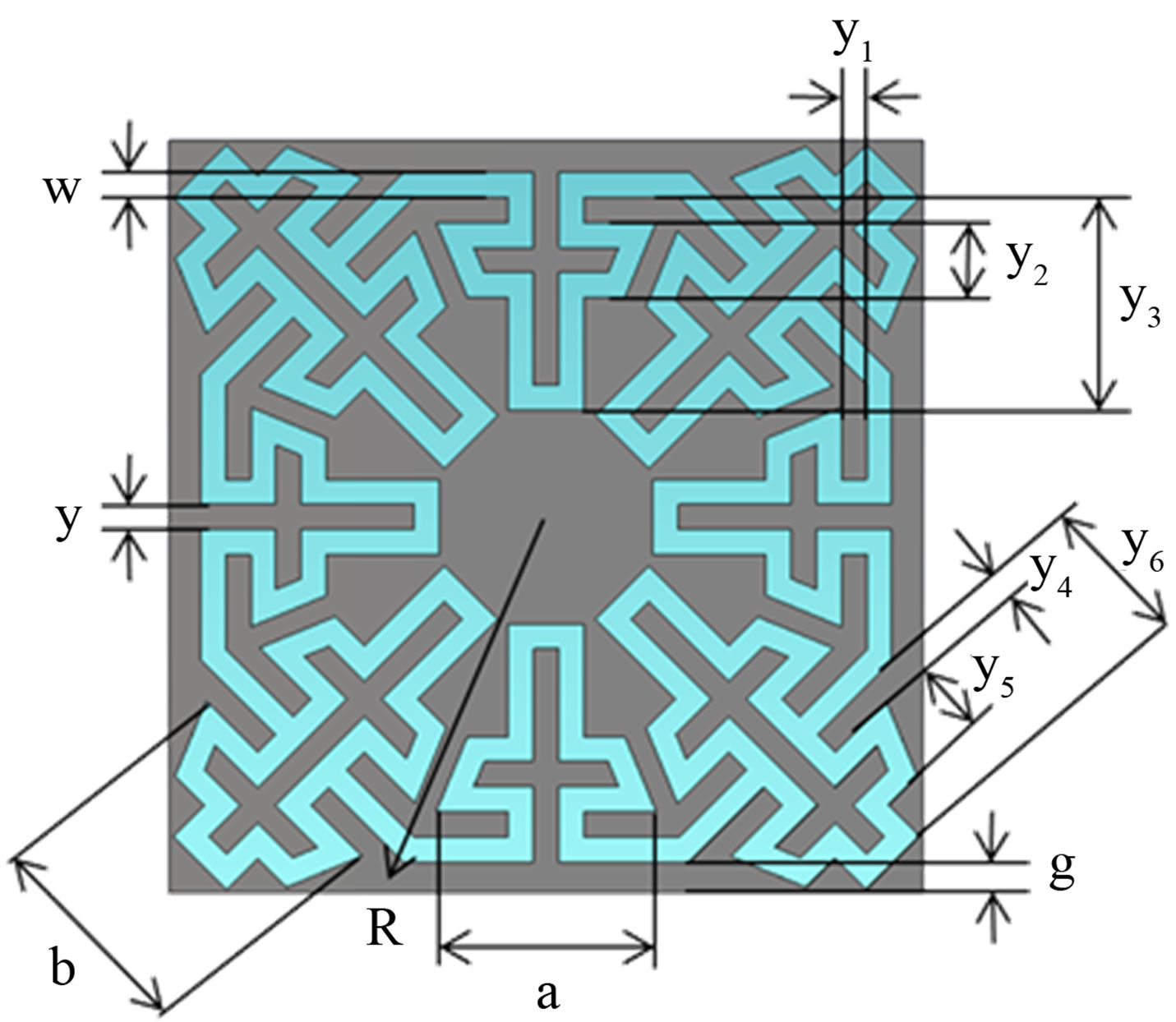
Figure 1. Geometry of the octagonal FSS.

Table 1. Parameters of the octagonal pattern.
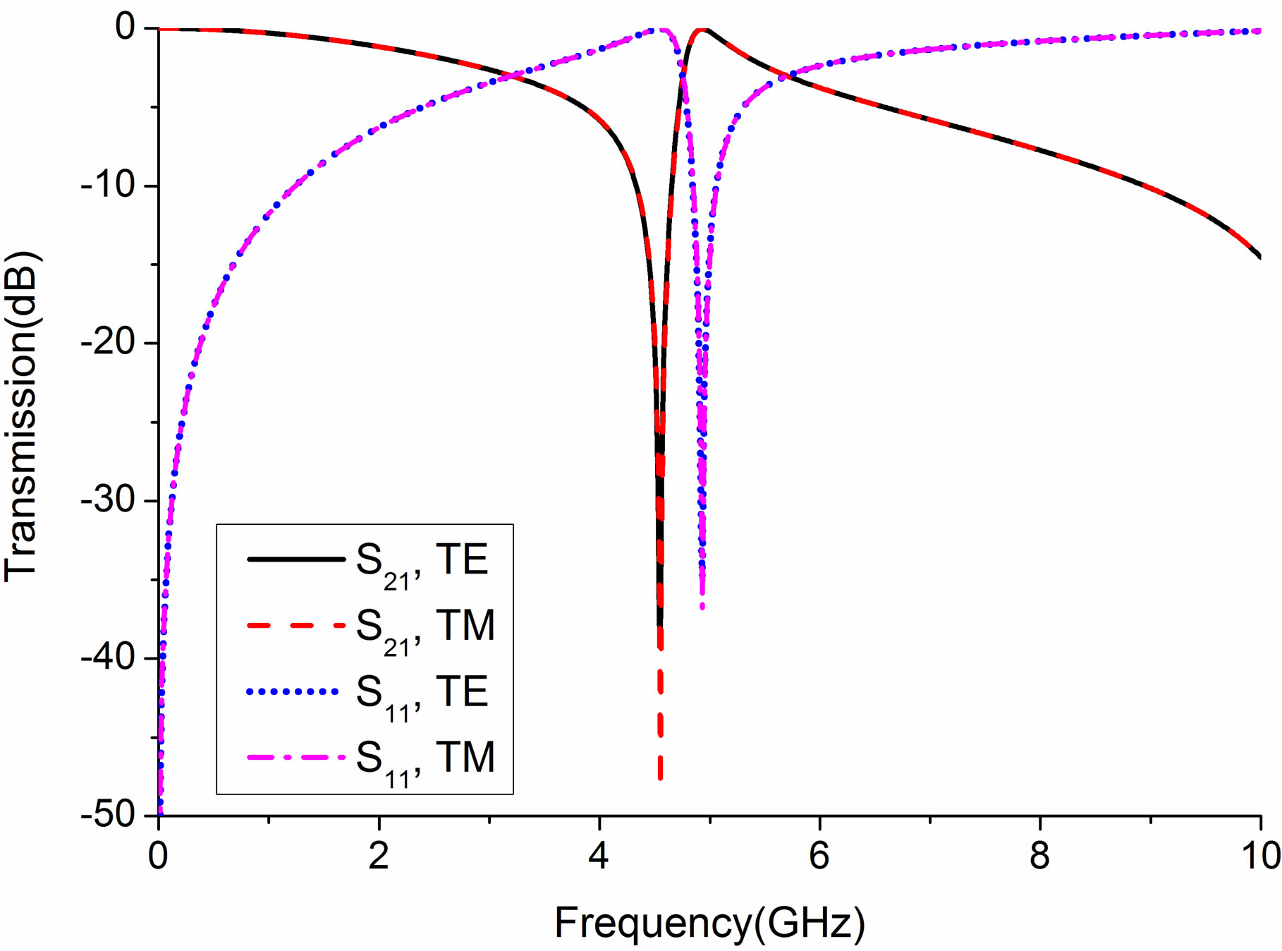
Figure 2. Transmission performances of the octagonal FSS for normal incident waves.
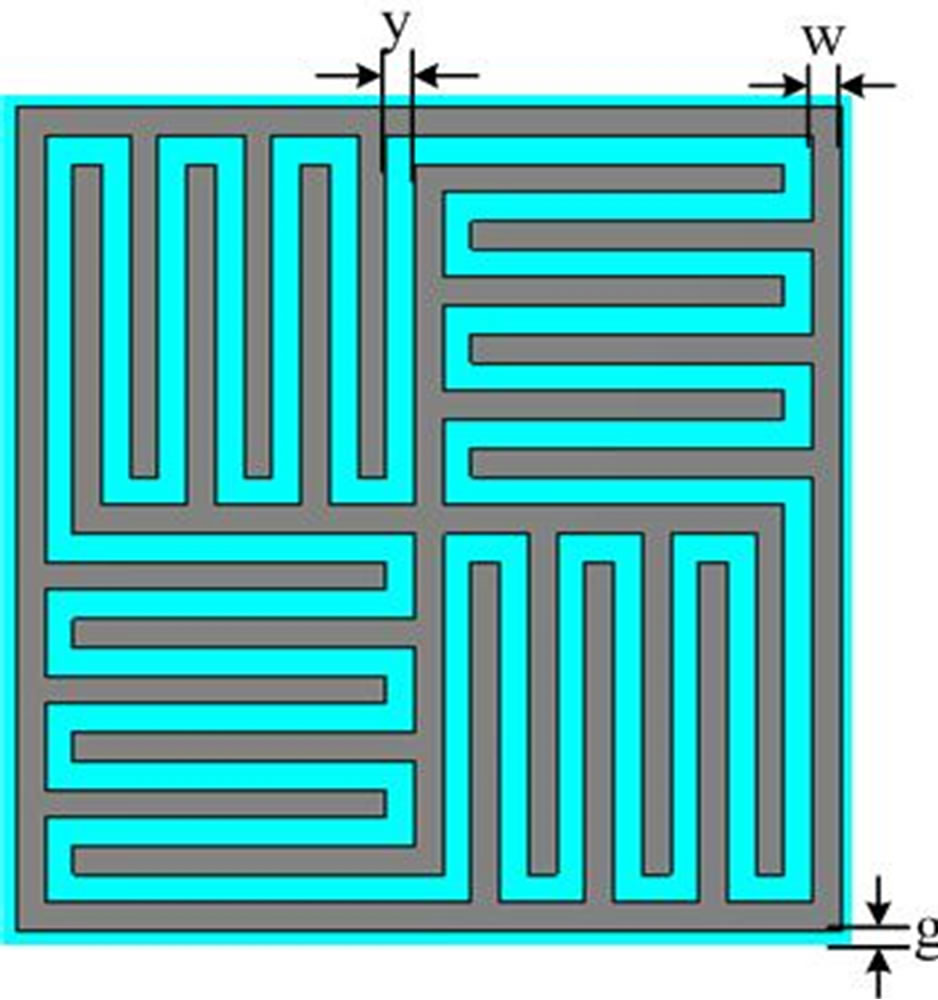
Figure 3. Geometry of the additional layer.

Figure 4. Basic idea of additional layer.
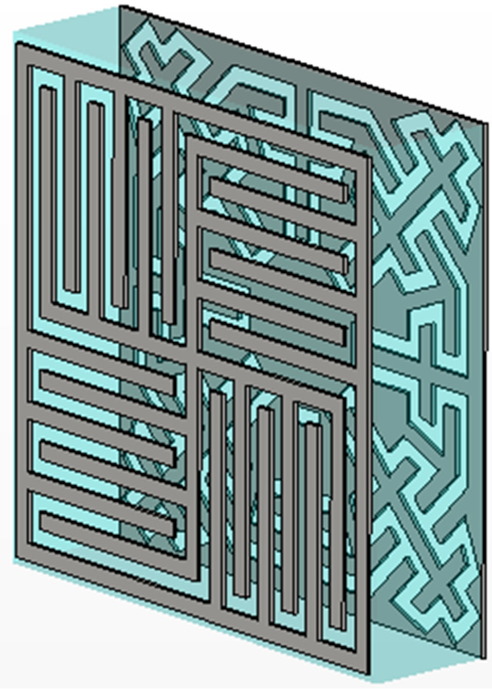
Thus, by adding the additional metallic layer, the profile of the FSS’s cell can be further miniaturized. The structure of the combinational FSS is presented in Figure 5. The dimension of both the metallic layers are the same, with length d = 5.8 mm and thickness t = 0.05 mm. Since the normal fabrication precision is about 0.2 mm, the width and gap of the metal strips we simulate is l = w = 0.2 mm. The material of the dielectric substrate is FR4, with the relative dielectric constant εr = 2.65, loss tangent tanδ = 0.001 and width t = 1.5 mm. The gap between the outside metal loop and cell boundary g = 0.1 mm.
Simulation results of the transmission performances for the additional metallic layer structure is shown in Figure 6 and for the combinational FSS is presented in Figure 7. It can be observed that the additional layer itself forms a band-stop FSS. After combination with the octagonal metallic layer, equivalent capacitance of the entire structure is increased, and as a result further improves the miniaturization performance. The resonant frequency of the combinational FSS is about 4.07 GHz for both S21 and S11 with the relative cell dimension is about 0.0814λ × 0.0814λ, which is approximately only 62.14% of the octagonal FSS’s size. However, it should be noticed that because of adding another metallic layer the wide-bandwidth characteristic of the original octagonal FSS is weakened, with transmittance value of the resonant frequency decreases from –0.02 dB to –1.20 dB for S21 and increases from –29.50 dB to –6.23 dB for S11. Therefore, the combinational FSS should not be used for applications with too wide bandwidth or large-amount band-pass required.
2.3. Angle and Polarization Stability
Since the characteristics of the FSS should be stable for different situations, transmission performances for waves of different polarizations and incident angles are also simulated. The results for the octagonal FSS are presented in Figures 8 and 9 and for the combinational FSS are presented in Figures 10 and 11. It can be observed that for both structures with the increase of incident angles, pass bands for TE-polarized waves decrease slightly, while for TM-polarized waves increase slightly. The resonant frequencies are basically stable with the relatively deviation no more than 3.5% in any cases. Therefore all
 (a)
(a)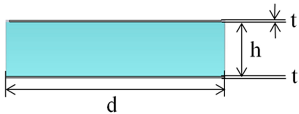 (b)
(b)
Figure 5. Geometry of the combinational FSS. (a) Perspective view; (b) Side view.
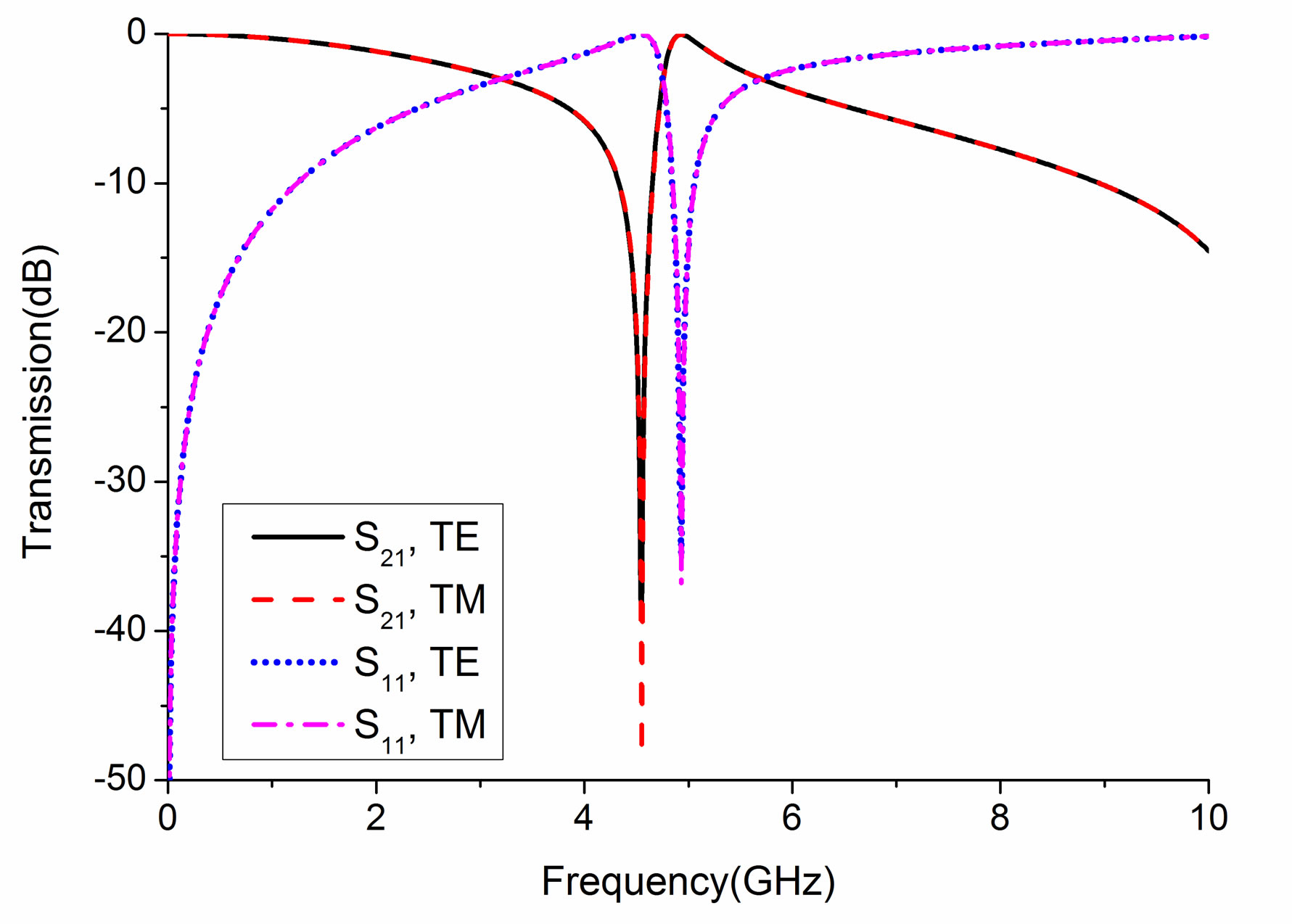
Figure 6. Transmission performances of the additional layer for normal incident waves.

Figure 7. Transmission performances of the combinational FSS for normal incident waves.
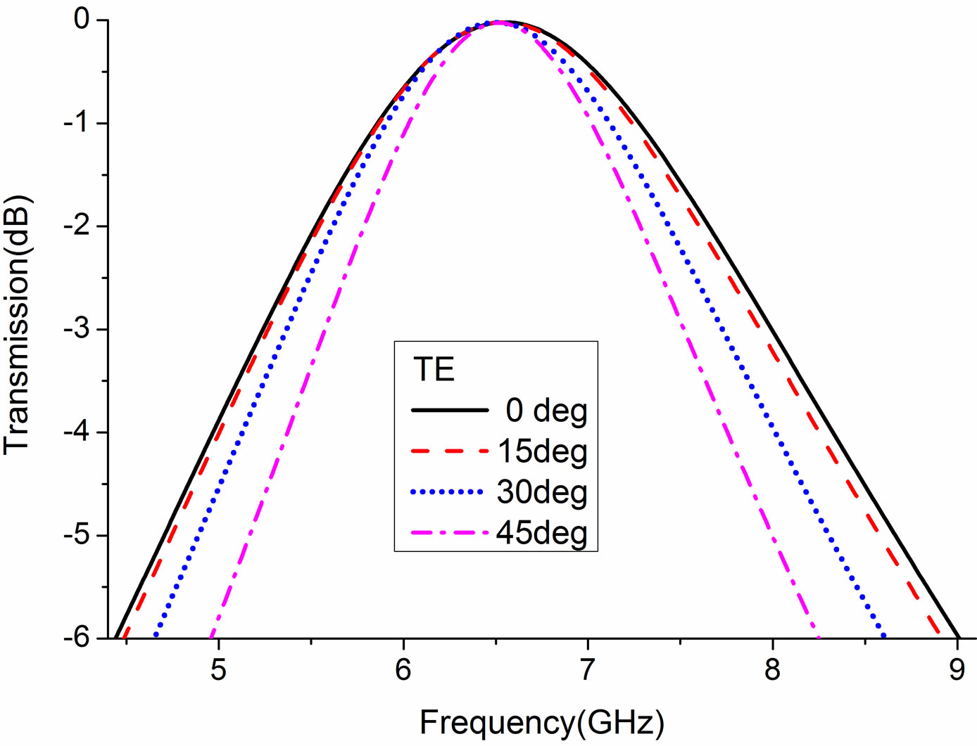
Figure 8. Transmission performances of the octagonal FSS for TE-polarized waves of different incident angles.
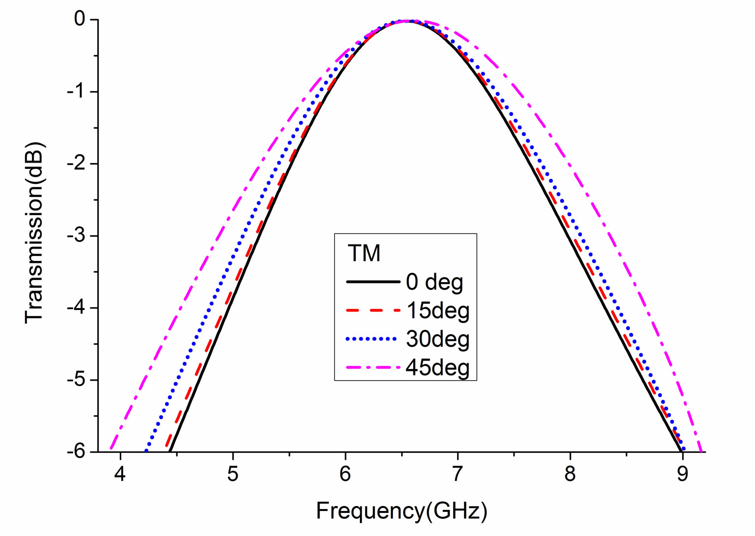
Figure 9. Transmission performances of the octagonal FSS for TM-polarized waves of different incident angles.
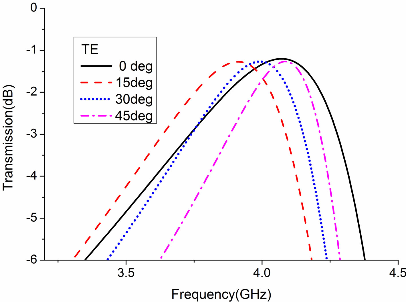
Figure 10. Transmission performances of the combinational FSS for TE-polarized waves of different incident angles.
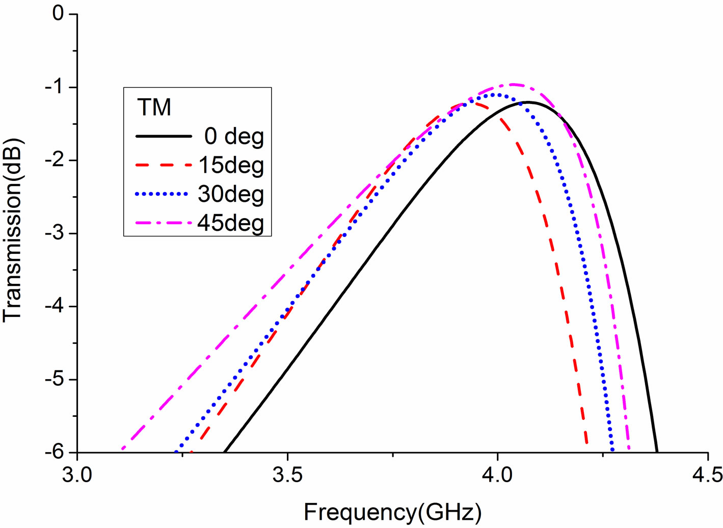
Figure 11. Transmission performances of the combinational FSS for TM-polarized waves of different incident angles.
the transmission responses remain in good states, which guarantee the practicability of the proposed FSS.
3. Conclusion
In this paper, we propose a band-pass FSS with improved miniaturization performance by adding an additional specially designed metallic layer. By this means the dimension of the unit cell can be reduced to less than two thirds of the original one, and at the same time keeping its good angle and polarization stability. Thus, the proposed FSS could become an ideal choice for practical application, and the method we used is valid and promising for future study.
4. Acknowledgements
This work was supported by the National Natural Science Foundation of China under Grant 60801015 and 61001036.
REFERENCES
- F. O’Nians and J. Matson, “Antenna Feed System Utilizing Polarization Independent Frequency Selective Intermediate Reflector,” US Patent No. 3231892, 25 January 1966.
- R. Ott, R. Kouyoumjian and L. Peters Jr., “Scattering by a Two Dimensional Periodic Array of Narrow Plates,” Radio Science, Vol. 2, No. 11, 1967, pp. 1347-1359.
- C. C. Chen, “Scattering by a Two-Dimensional Periodic Array of Conducting Plates,” IEEE Transitions on Antennas and Propagation, Vol. 18, No. 5, 1970, pp. 660- 665.
- R. K. Munk and L. Peters Jr., “Reflection Properties of Periodic Surfaces of Loaded Dipoles,” IEEE Transitions on Antennas and Propagation, Vol. 19, No. 5, 1971, pp. 612-617. doi:10.1109/TAP.1971.1139995
- J. Huang, T.-K. Wu and S.-W. Lee, “Tri-Band Frequency Selective Surface with Circular Element,” IEEE Transitions on Antennas and Propagation, Vol. 42, No. 2, 1994, pp. 204-207.
- D. Sarkar, P. P. Sarkar and S. K. Chowdhury, “Experimental Investigation of a Tri-Band Frequency Selective Surface,” Microwaves and Optical Technology Letters, Vol. 41, No. 6, 2004, pp. 511-512. doi:10.1002/mop.20187
- R. Mittra, C. H. Chan and T. Cwik, “Techniques for Analyzing Frequency Selective Surface—A Review,” Proceeding of the IEEE, Vol. 76, No. 12, 1988, pp. 1593- 1615.
- K. Sarabandi and N. Behdad, “A Frequency Selective Surface with Miniaturized Elements,” IEEE Transactions and Antennas Propagation, Vol. 55, No. 5, 2007, pp. 1239-1245. doi:10.1109/TAP.2007.895567
- R.-R. Xu, Z.-Y. Zong and W. Wu, “Low-Frequency Miniaturized Dual-Band Frequency Selective Surfaces with Close Band Spacing,” Microwave and Optical Technology Letters, Vol. 51, No. 5, 2009, pp. 1238-1240. doi:10.1002/mop.24338
- W. T. Wang, P. F. Zhang, S. X. Gong, B. Lu, J. Ling and T. T. Wan, “Compact Angularly Stable Frequency Selective Surface Using Hexagonal Fractal Configurations,” Microwave and Optical Technology Letters, Vol. 51, No. 11, 2009, pp. 2541-2544. doi:10.1002/mop.24676
- C.-N. Chiu and K.-P. Chang, “A Novel MiniaturizedElement Frequency Selective Surface Having a Stable Resonance,” IEEE Antennas and Wireless Propagation Letters, Vol. 8, 2009, pp. 1175-1177. doi:10.1109/LAWP.2009.2034766
- X.-D. Hu, X.-L. Zhou, et al., “A Miniaturized Dual-Band Frequency Selective Surface (FSS) with Closed Loop and Its Complementary Pattern,” IEEE Antennas and Wireless Propagation Letters, Vol. 8, 2009, pp. 1374-1377. doi:10.1109/LAWP.2009.2039110
- T. Zhang, G.-H. Yang, W.-L. Li and Q. Wu, “A Novel Frequency Selective Surface with Compact Structure and Stable Responses,” 9th International Symposium on Antennas Propagation and EM Theory (ISAPE), Guangzhou, 29 November-2 December 2010, pp. 932-935.