Journal of Electromagnetic Analysis and Applications
Vol.4 No.1(2012), Article ID:17147,6 pages DOI:10.4236/jemaa.2012.41002
Wideband Sierpinski Carpet Fractal Shaped Cylindrical Dielectric Resonator Antenna for X-Band Application
![]()
1ETCE Department, MP Christian College of Engineering and Technology, Bhilai, India; 2Microwave and Antenna Research Laboratory, ECE Department, National Institute of Technology Durgapur, Durgapur, India; 3Electronic Science Department, Berhampur University, Berhampur, India; 4ETCE Department, Jadavpur University, Jadavpur, India.
Email: dipalisoren@yahoo.co.in, {rowdragahtak, drp_ju}@yahoo.com, prof.r.k.mishra@gmail.com
Received November 1st, 2011; revised December 3rd, 2011; accepted December 14th, 2011
Keywords: Wideband; Dielectric Resonator Antenna (DRA); Fractal; Sierpinski Carpet
ABSTRACT
In this paper, a wideband Sierpinski carpet patterned cylindrical Dielectric Resonator Antenna (DRA) operating in the X-Band is proposed. This DRA is realized from low cost Teflon. An impedance bandwidth of 50% is obtained covering the entire X-band with similar radiation pattern throughout the band. The average peak gain within the band is about 5.5 dBi.
1. Introduction
Dielectric resonator antennas (DRAs) have been subjected to many investigations since their introduction in 1983 [1]. The DRA is useful for high frequency applications where Ohmic losses become predominant for conventional metallic antennas. In addition, they offer higher bandwidths and gain when compared with microstrip patch antennas. Over the past few years researchers have tried to improve the impedance bandwidth of these DRAs to increase its functionality. Wideband DRA has been demonstrated for cylindrical DRA (CDRA) by Chair et al. [2] and for rectangular DRA by Li and Leung [3]. Systematic analysis of improving bandwidth using this mode merging technique has been reported by Young and Long [4]. In [4] it was revealed that the actual reason for wideband operation of CDRA was due to unequal rate of variation in resonant frequency of the TM110 and TM111 modes with change in radius to height ratio as shown in Figure 1 illustrating an edge fed CDRA.
Guha and Antar [5] reported a new design by using a set of four CDRAs symmetrically arranged around a centrally located coaxial probe covered by a dielectric rod to achieve wideband performance by merging closely spaced resonances. In [6] Walsh et al. investigated a set of three different configurations of CDRA like the stacked, core plug embedded and embedded stacked respectively to achieve wideband resonance characteristics. It was reported in [6] that for core plug embedded CDRA maximum impedance bandwidth could be achieved by simultaneously making the embedded plug region dielectric constant as one and ensuring the maximum occupancy of the plug region. Keefe and Kingsley [7] reported RF range liquid DRA that uses water as dielectric which adds a new range of dielectric antenna research. Lai et al. [8] revisited the radiation efficiency of DRA and using Wheeler cap technique and confirmed that radiation efficiency of DRA is much higher than microstrip antenna millimeter wave frequencies. Recently integration of DRA with other circuits for on chip application using silicon substrate was reported in [9].
Chen et al. has proposed a miniature dual-band dielectric resonator antenna with a parasitic c-slot fed by microstrip line [10]. The proposed antenna achieved bandwidth and of 3.3% & 4.3 dBi at 2450 MHz and 5.7% & 3.8 dBi at 5640 MHz.
The enhanced radiation characteristics of a cylindrical DRA are presented by A. Singh and Satish K.Sharma [11] by employing the dual coaxial probes in the differential feed arrangement. The DRA offers an impedance bandwidth of 68% and broadside radiation patterns with good gain and low cross-polarization levels. In comparison to this, a similar single probe fed DRA provided 82% bandwidth but with the mix of the omni-directional and directional radiation patterns with high cross-polarization levels.
Liboli Z. et al. presented a broadband dielectric resonator antenna, formed by carving out notches from cylindrical geometry to form the bowtie shape and fed by coaxial probe on one of the notched sides [12]. The proposed bowtie DRA combines shape deformation with
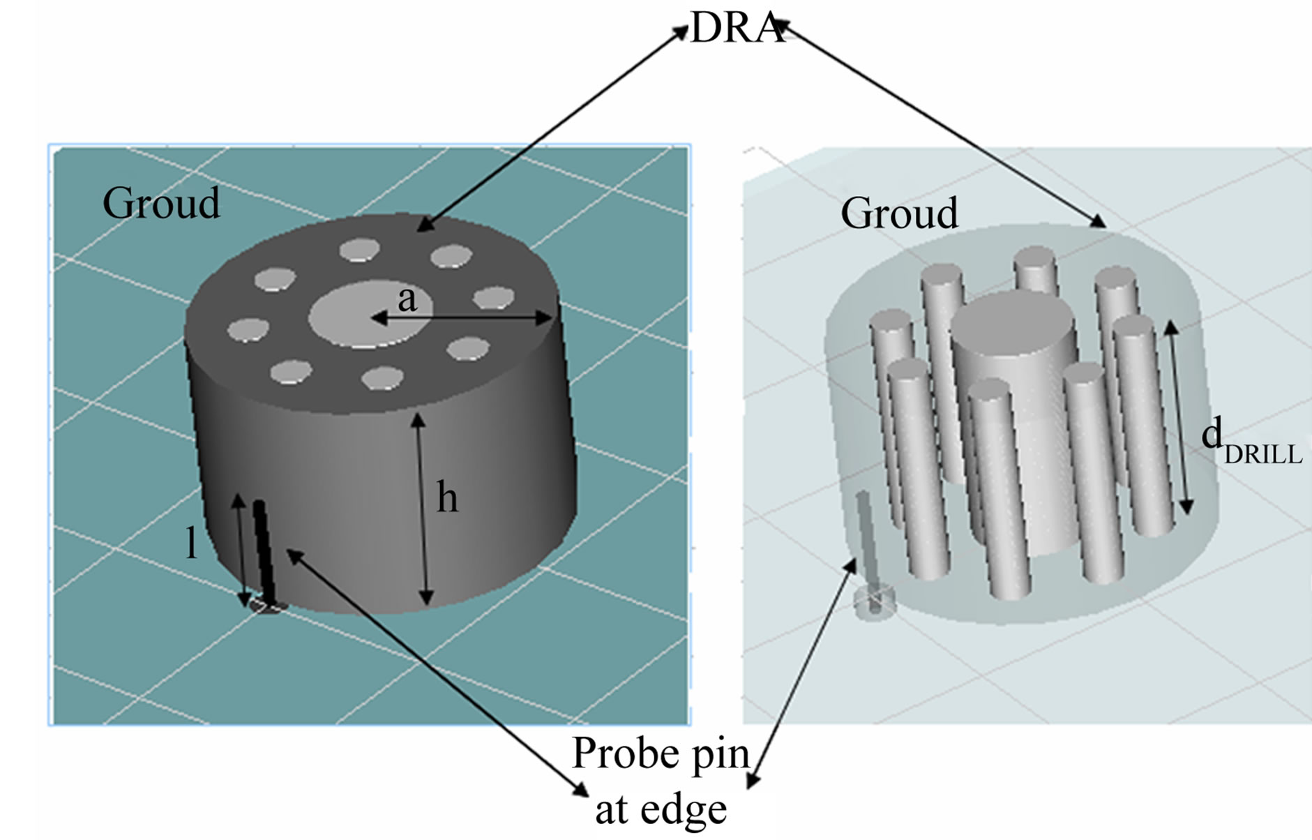
Figure 1. Geometry of a typical cylindrical dielectric resonator antenna. The main design dimensions are the radius “a” and height “h” as indicated.
low permittivity resonator achieved impedance bandwidth of 49.4% covering frequency range of 4.194 - 6.944 GHz. The simulated and measured radiation patterns are consistent throughout the operational bandwidth.
In this work we have presented a rule based method to achieve wideband performance by drilling out Sierpinski carpet fractal patterned regions from a CDRA. Section 2 deals with antenna design methodology and parametric study. This is followed by resonance and radiation characteristics in Section 3 with final concluding remarks in Section 4.
2. Antenna Design and Parametric Study
The proposed antenna is analyzed and parametrically studied using CST Microwave Studio™. As discussed in the previous section that a wide bandwidth can be achieved by proper merging of closely spaced modes, similarly the first design step was to parametrically vary radius to height ratio for a CDRA with εr = 2.1 (Teflon). The radius of the Teflon rod based CDRA is taken as 19 mm. For a height of 24 mm the closely spaced resonances merged resulting in a wide impedance bandwidth as shown in Figure 2.
This is followed by drilling out from the centre a cylindrical region of radius a′ which is 1/3 the radius “a” of the original cylinder. This CDRA is a first iteration Sierpinski carpet fractal patterned CDRA with edge feed which is named as SCFCDRAEFI1. Similarly the second iteration is created by further drilling out eight cylinders of radius  where
where  is one third of
 . This is named as SCFCDRAEFI2 and its return loss plotted against frequency is shown in Figure 3. There is a slight improvement in impedance bandwidth as compared to the first iteration and the original CDRA.
The excitation is a Z-directed coaxial probe with the length “l” mm and the radius r = 0.635 mm. The probe is located at the edge circumference of Cylindrical DRA
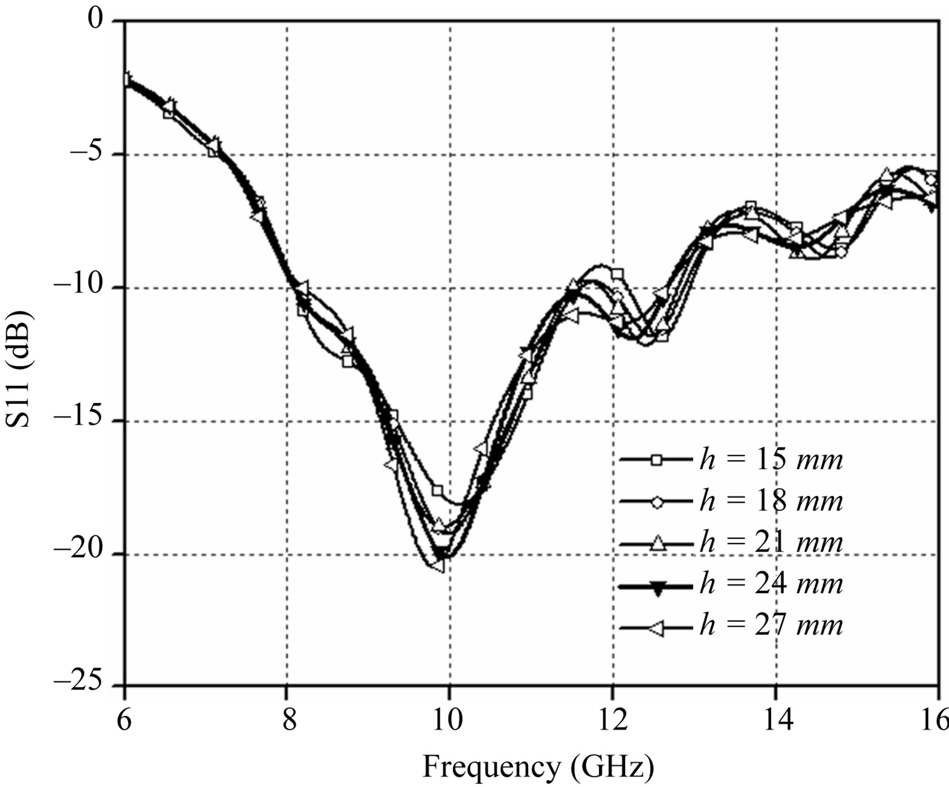
Figure 2. Simulated S11 (dB) with a different DRA height (h).
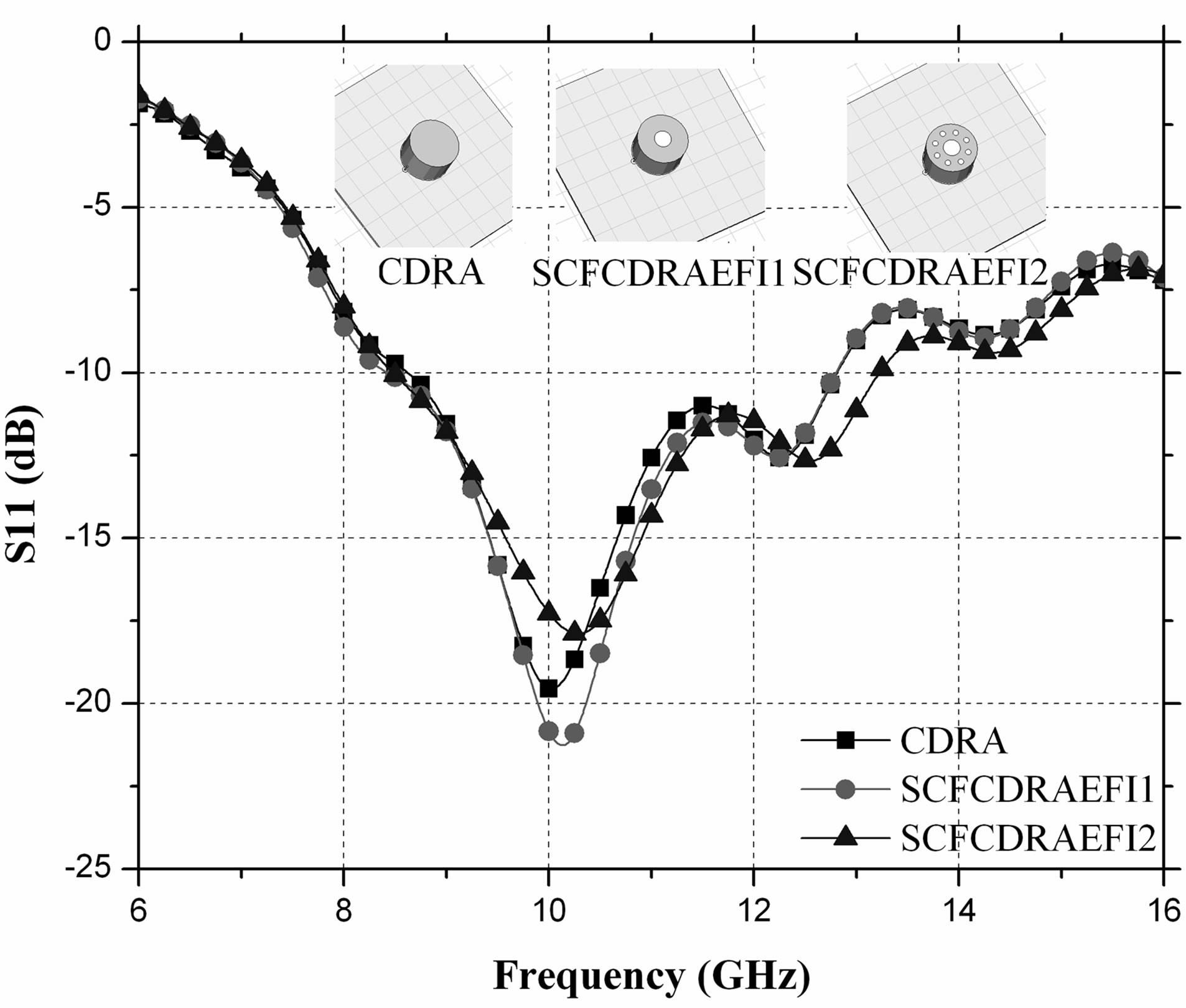
Figure 3. Comparison of S11(dB) plot of a typical CDRA with first and second iteration Sierpinski carpet fractal CDRA with SMA probe feed at the circumference.
and connected to a SMA connector. The probe pin length “l” is parametrically varied to observe its effect on resonance frequency. It is seen from Figure 4 that the resonance frequency decreases as probe pin length increases. A probe pin length of 6 mm was chosen for which 10 GHz centre frequency could be achieved.
The depth of drill “dDRILL” is also parametrically varied to observe its effect on impedance bandwidth as shown in Figure 5. It is observed that increasing the depth of drill improves impedance bandwidth. When the depth of drill is equal to height of DRA the impedance bandwidth is maximum.
To further improve the bandwidth it was desirous that different resonances must be properly excited within the SCFCDRAEFI2. This could be achieved by shifting the
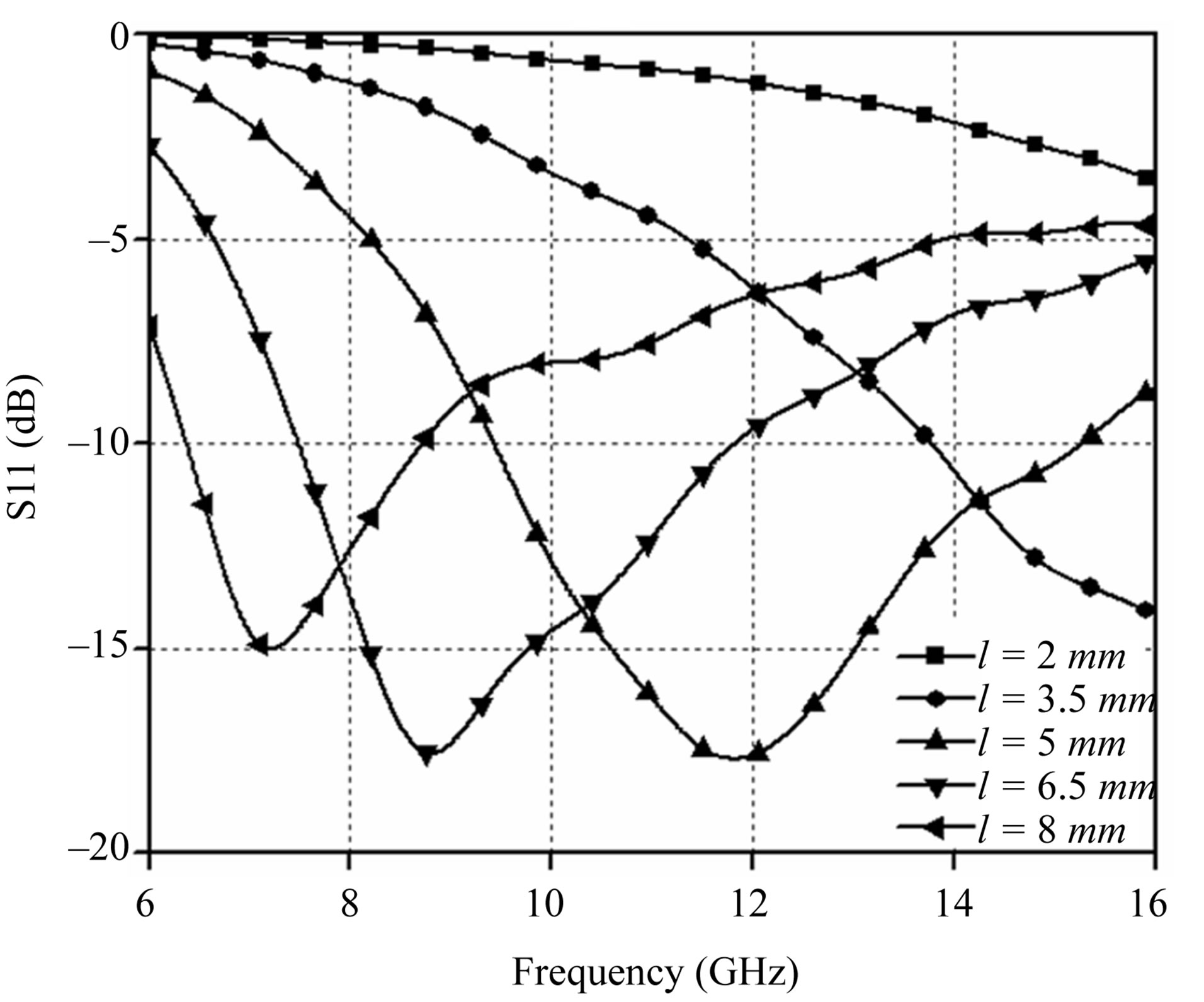
Figure 4. Variation in S11 curves for different pin lengths in circumference fed Sierpinski carpet fractal CDRA of second iteration.
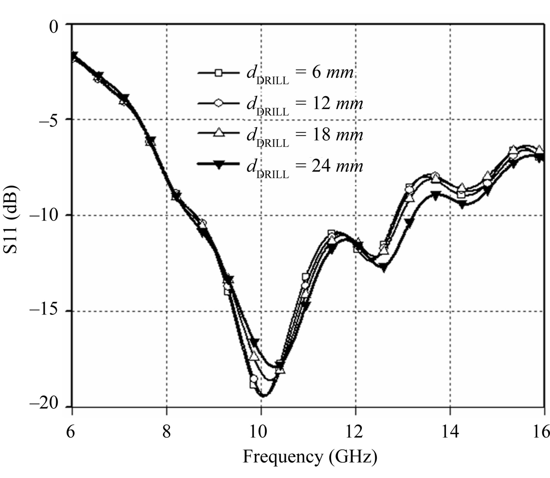
Figure 5. Variation in S11 (dB) curves after varying the depth of the drilled out region in Sierpinski carpet fractal CDRA of second iteration.
position of feed from the circumference to an inner point. This new design is named as inset fed second iteration Sierpinski carpet patterned CDRA which in short form is written as SCFCDRAIFI2. To insert a probe in a simple CDRA holes need to be drilled. Here, as a cylindrical region of radius  is already removed from the original CDRA for designing SCFDRAEFI2 so it is easy for inserting the coaxial probe pin in the inner circumference as shown in Figure 6.
To further study the effect of the drilled out regions the holes were filled with dielectric materials and the effect on resonance behavior was observed. It is seen from Figure 7 that the maximum bandwidth and proper
 (a)
(a)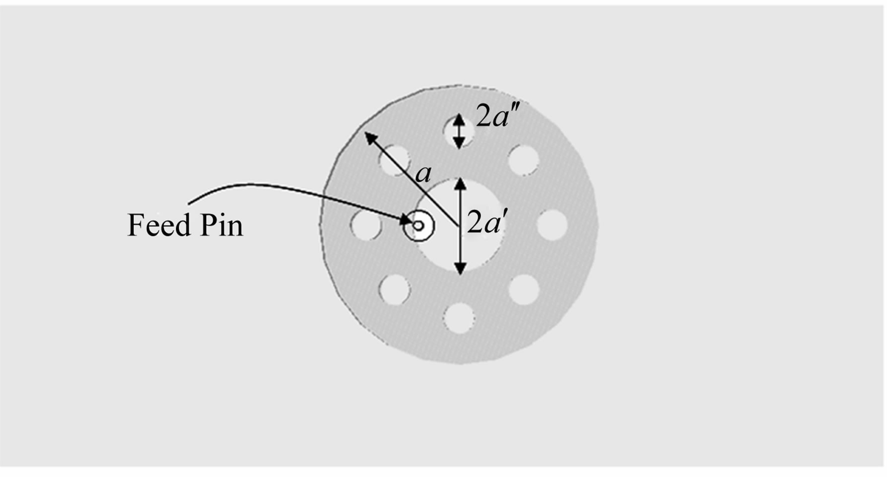 (b)
(b)
Figure 6. Illustration of the proposed antenna, (a) side view and (b) top view.
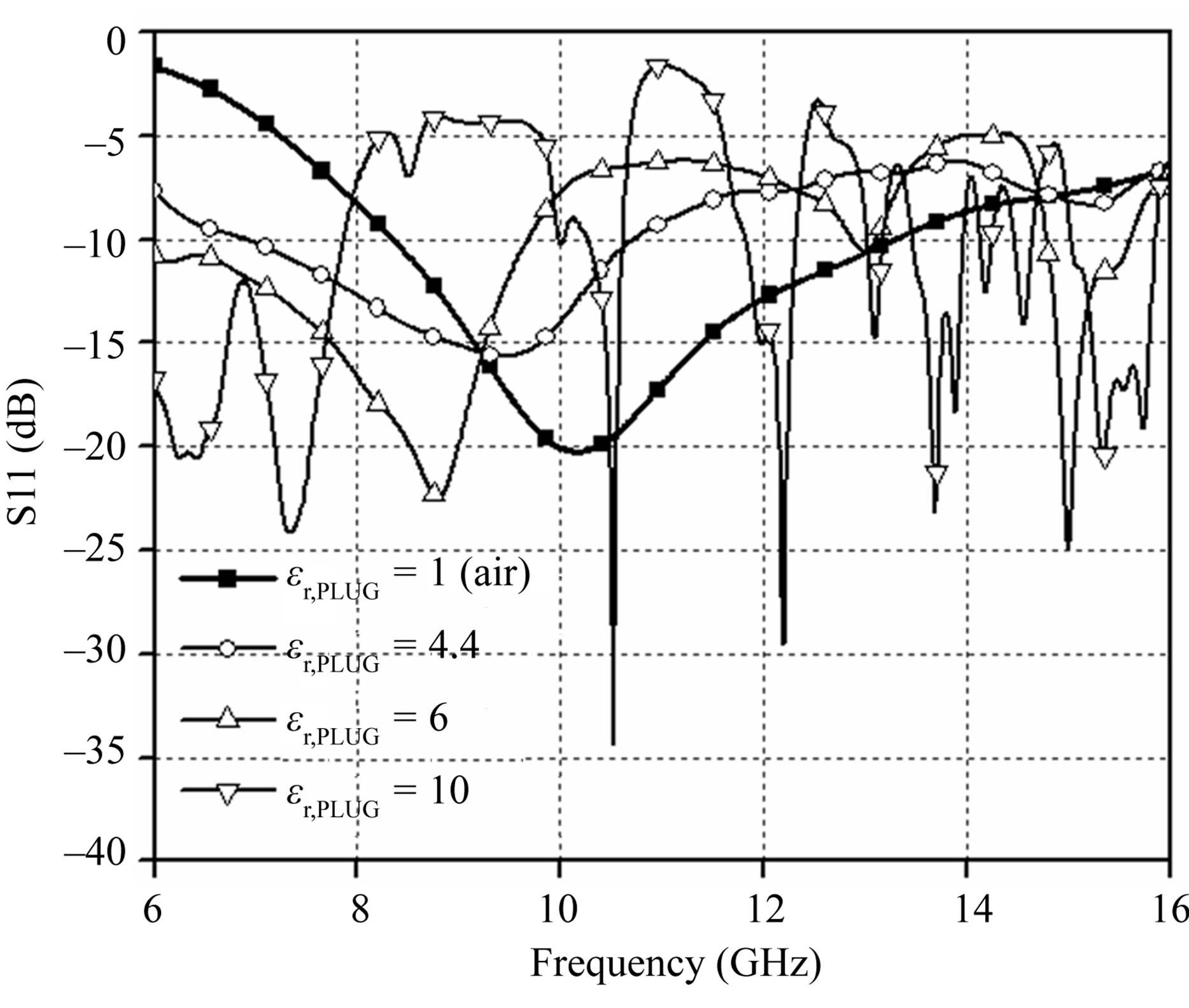
Figure 7. Variation in S11 (dB) curves for different values of permittivity of plugged region in fractal cylindrical DRA of second iteration.
frequency tuning is achieved using air i.e. by simply removing the drilled out material.
3. Results and Discussion
The proposed antenna is analyzed using CST Microwave Studio™. From the S11 (dB) plot of the initial designs of the antenna as shown in Figure 3 it is seen that there is an improvement of approximately 6% in impedance bandwidth after first iteration and improvement of approximately 14% after second iteration is achieved. The impedance bandwidths of the individual designs are also tabulated in Table 1.
The simulated S11 (dB) of the inset feed Sierpinski carpet fractal CDRA, as illustrated in Figure 5, is given in Figure 8. The impedance bandwidth is calculated to be 50%.
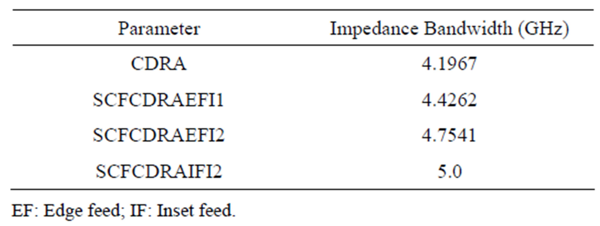
Table 1. Impedance bandwidth of various designs of fractal based CDRA SCFCDRA: Sierpinski carpet fractal cylindrical dielectric resonator antenna.
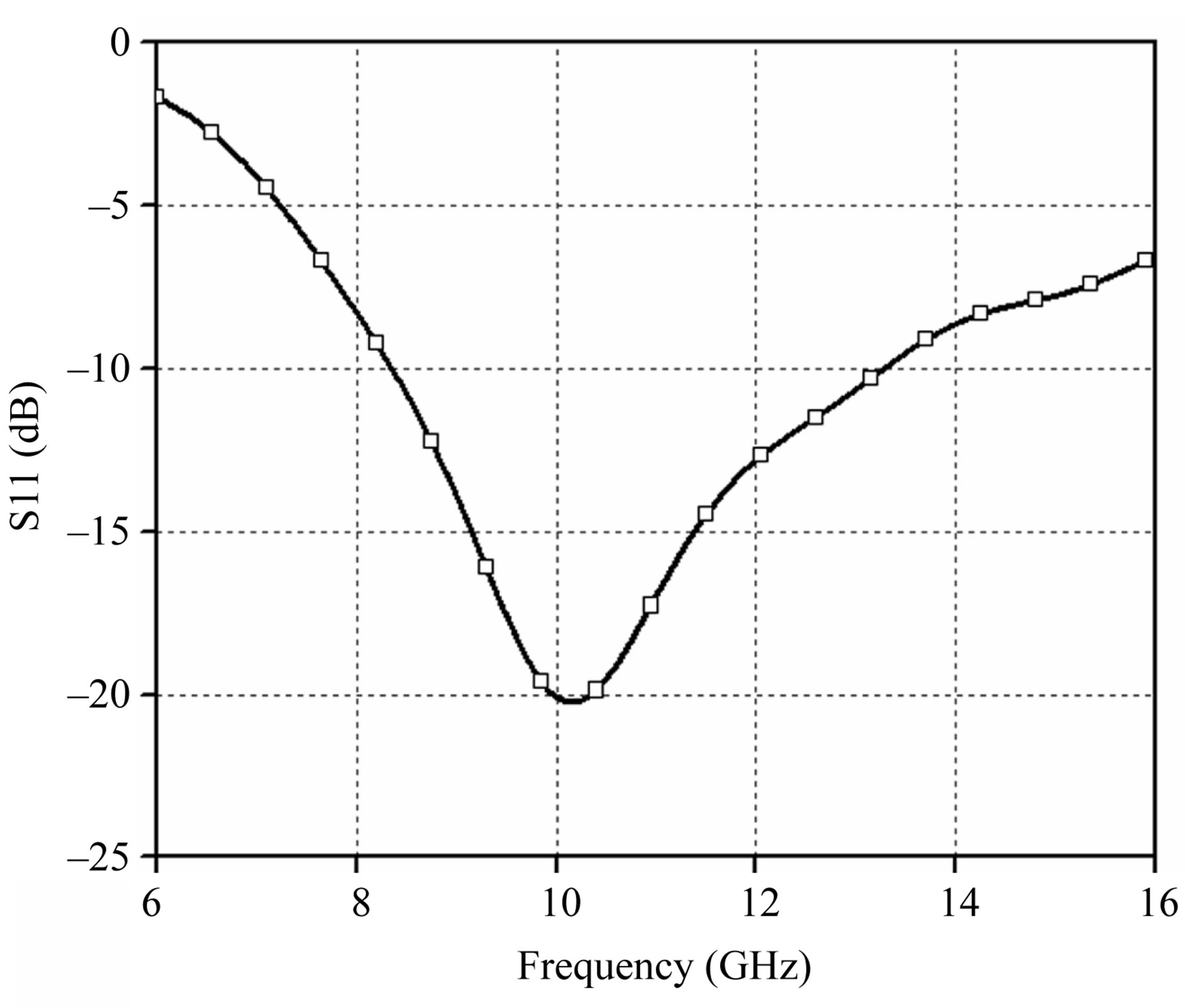
Figure 8. Return loss plot of inset fed Sierpinski carpet fractal CDRA of second iteration.
The E-field distribution inside the fractal DRA (FDRA) is illustrated in Figure 9 for three frequencies at 9 GHz, 10 GHz and 11 GHz. At lower frequency of 9 GHz it is observed that the field is confined within the DRA confirming that it is the fundamental mode. With a definite pattern of drilled off region which in this case is a fractal geometry, the resonance frequencies could be fine tuned resulting in a wide impedance bandwidth.
The radiation pattern in E-theta for Phi = 0˚ and Phi = 90˚ are shown in Figure 10. A similar radiation characteristic is observed within the band in both cut planes. The simulated antenna peak gain against frequency of inset fed Sierpinski carpet fractal CDRA of second iteration is shown in Figure 11. The simulated peak gain varies from 5.25 dBi to 6.25 dBi within the band. At the resonant frequency 10 GHz the peak gain is 5.511 dBi. The computed efficiency is found to be above 90%.
4. Conclusion
A new broadband cylindrical dielectric resonator antenna is realized using drilling off Sierpinski carpet fractal shaped holes in the original cylindrical dielectric resonator. By shifting the feed position from the circumference to an inset position it is seen that matching over a wideband covering the entire X-band becomes uniform. In this design, impedance bandwidth of 50% is obtained. In addition, the antenna cost is very low as an attempt has been made to realize DRA using low dielectric permittivity material like Teflon. With these features, this design
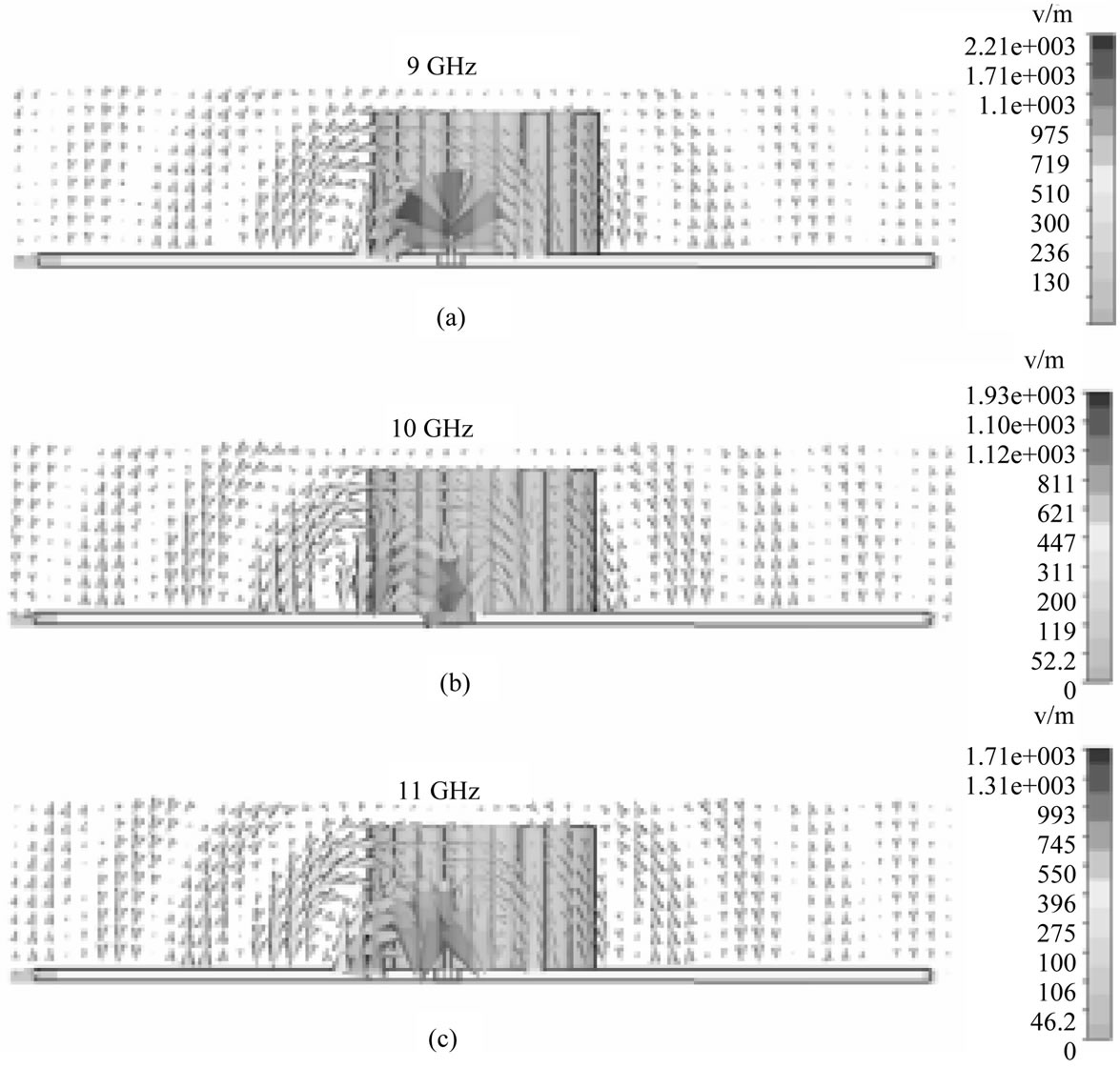
Figure 9. E-field distribution inside the fractal DRA as well as near the antenna at (a) 9 GHz; (b) 10 GHz and (c) 11 GHz.
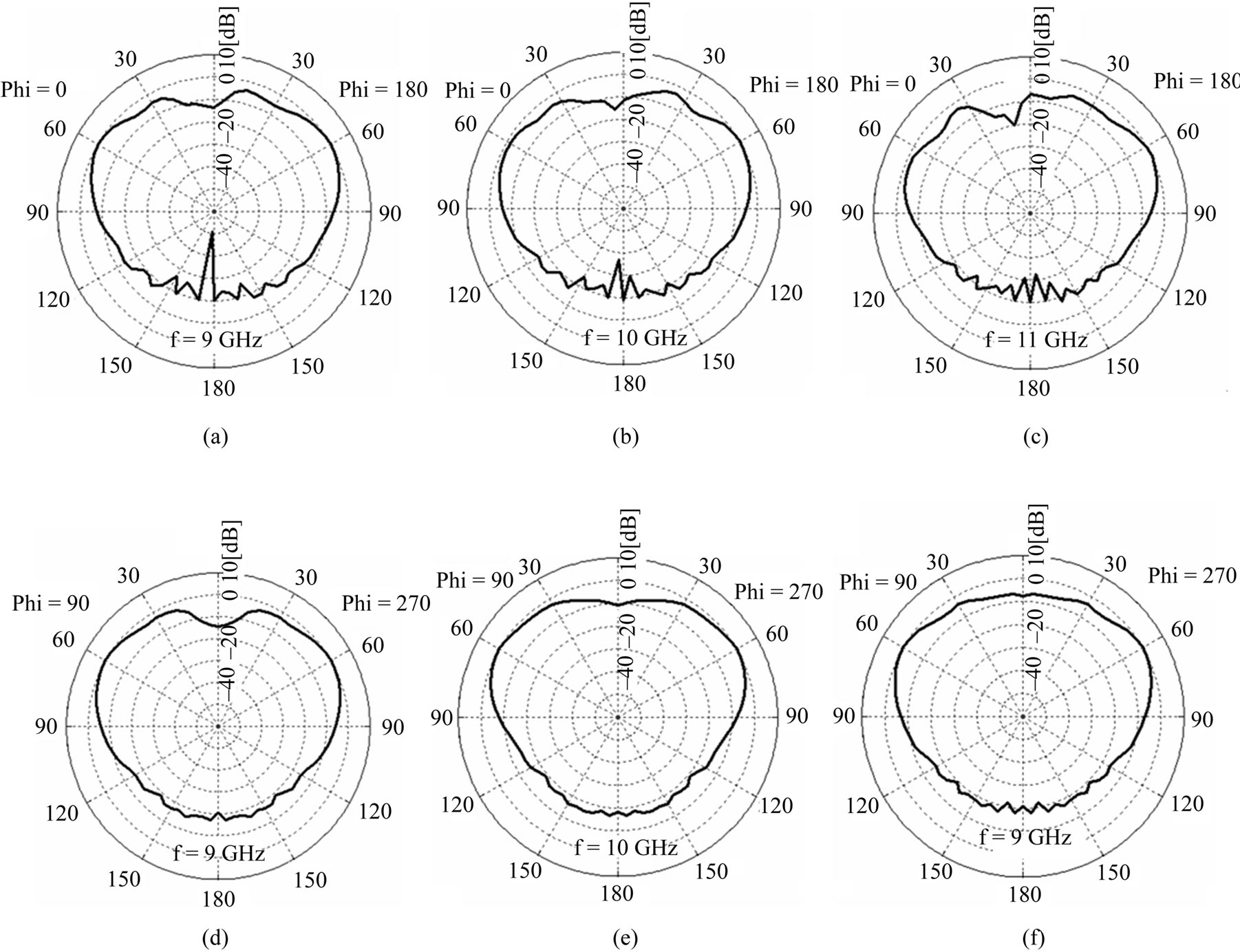
Figure 10. Simulated radiation patterns. E-theta pattern for Phi = 0 deg at (a) 9 GHz; (b) 10 GHz and (c) 11 GHz. E-theta for Phi = 90 deg at (d) 9 GHz; (e) 10 GHz and (f) 11 GHz respectively.
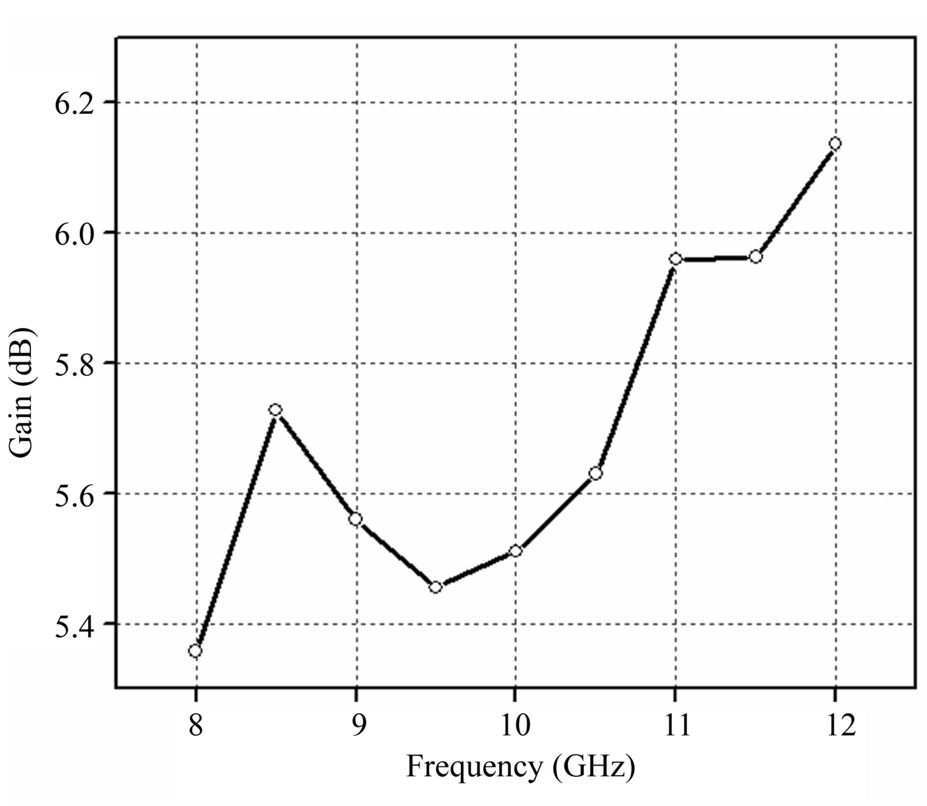
Figure 11. Simulated antenna peak gain of inset fed Sierpinski carpet fractal CDRA of second iteration against frequency.
of fractal CDRA is suitable for broadband wireless communication systems like long range RFID operating in X-band.
REFERENCES
- S. A. Long, M. W. Mcallister and L. C. Shen, “The Resonant Cylindrical Dielectric Cavity Antenna,” IEEE Transactions on Antennas and Propagation, Vol. 31, No. 3, 1983, pp. 406-412. doi:10.1109/TAP.1983.1143080
- R. Chair, A. A. Kishk and K. F. Lee, “Wideband Simple Cylindrical Dielectric Resonator Antenna,” IEEE Microwave and Wireless Components Letters, Vol. 15, No. 4, 2005, pp. 241-243. doi:10.1109/LMWC.2005.845719
- B. Li and K. W. Leung, “Strip Fed Rectangular Dielectric Resonator Antennas with/without a Parasitic Patch,” IEEE Transactions on Antennas and Propagation, Vol. 53, No. 7, 2005, pp. 2200-2207. doi:10.1109/TAP.2005.850745
- C. S. De Young and S. A. Long, “Wideband Cylindrical and Rectangular Dielectric Resonator Antennas,” IEEE Antennas and Wireless Propagation Letters, Vol. 53, No. 5, 2006, pp. 426-429.
- D. Guha and Y. M. M. Antar, “Four-Element Cylindrical Dielectric Resonator Antenna for Wideband MonopoleLike Radiation,” IEEE Transactions on Antennas and Propagation, Vol. 54, No. 9, 2006, pp. 2657-2662. doi:10.1109/TAP.2006.880766
- A. G. Walsh, S. De Young and S. A. Long, “An Investigation of Stacked and Embedded Cylindrical Dielectric Resonator Antennas,” IEEE Antennas and Wireless Propagation Letters, Vol. 5, No. 1, 2006, pp. 130-133. doi:10.1109/LAWP.2006.873935
- S. G. O’keefe and S. P. Kingsley, “Tunability of Liquid Dielectric Resonator Antenna,” IEEE Antennas and Wireless Propagation Letters, Vol. 6, 2007, pp. 533-536. doi:10.1109/LAWP.2007.907916
- Q. H. Lai, G. Almpanis, C. Fumeaux, H. Benedickter and R. Vahldieck, “Comparison of the Radiation Patter Efficiency for the Dielectric Resonator Antenna and the Microstrip Antenna at Ka Band,” IEEE Transactions on Antennas and Propagation, Vol. 56, No. 11, 2008, pp. 3589- 3592. doi:10.1109/TAP.2008.2005551
- P. V. Bijumon, Y. M. M. Antar, A. P. Freundorfer and M. Sayer, “Dielectric Resonator Antenna on Silicon Substrate for System On-Chip Applications,” IEEE Transactions on Antennas and Propagation, Vol. 56, No. 11, 2008, pp. 404-3410. doi:10.1109/TAP.2008.2005537
- H.-M. Chen, Y.-K. Wang, Y.-F. Lin and S.-C. Pan, “A Compact Dual-Band Dielectric Resonator Antenna Using a Parasitic Slot,” IEEE Transactions on Antennas and Wireless Propagation Letters, Vol. 8, 2009, pp. 173-176. doi:10.1109/LAWP.2008.2001119
- A. Singh and S. K. Sharma, “Investigations on Wideband Cylindrical Dielectric Resonator Antenna with Directive Radiation Patterns and Low Cross Polarization,” IEEE Transactions on Antennas and Propagation, Vol. 58, No. 5, 2010, pp. 1779-1783. doi:10.1109/TAP.2010.2044330
- L. Z. Thamae and Z. P. Wu, “Broadband Bowtie Dielectric Resonator Antenna,” IEEE Transactions on Antennas and Propagation, Vol. 58, No. 11, 2010, pp. 3721-3725.