Journal of Electromagnetic Analysis and Applications
Vol. 3 No. 11 (2011) , Article ID: 8335 , 4 pages DOI:10.4236/jemaa.2011.311070
Design of Radome with Different Structures Based on Transformation Optics
![]()
1College of Science, Nanjing Forestry University, Nanjing, China; 2College of Information Science and Technology, Nanjing Forestry University, Nanjing, China.
Email: sys@njfu.com.cn
Received September 1st, 2011; revised October 7th, 2011; accepted October 20th, 2011.
Keywords: Transformation Optics, Metamaterials, Radome Structure
ABSTRACT
Basing on the transformation optics, we propose a kind of transformation method of compressing or stretching. With the method, we propose a design of transparent radome for different structures. The electromagnetic (EM) waves inside or outside the radome can transmit through the structure without any reflection. Numerical simulations confirm the function of the radome structures.
1. Introduction
Recently, much attention has been focused on the coordinate transformation method of Maxwells equations generalized by Pendry et al. [1-4]. The idea of transformation opens up many possibilities to control the electromagnetic (EM) fields at will. Besides cloaks, more wave manipulation strategies have been drawn out, such as EM field concentrators, rotators, direction changing, inside-out cloaks, and so forth [5-10]. Although such media would be very difficult to synthesize using conventional materials, artificially structured metamaterials offer a practical approach for the realization of transformation optics designs, given their ability to support a much wider and controllable range of electric and magnetic responses. It is believed that many other novel devices will be designed based on transformation media.
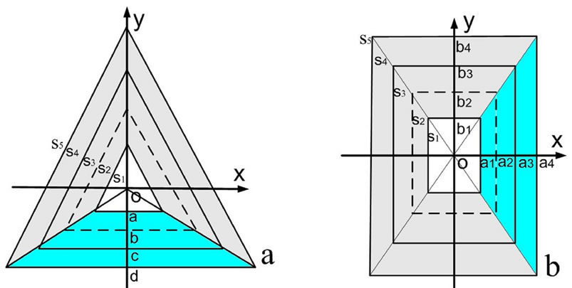
As we know, the protection radome of antennas is an important device. However, traditional radome has some disadvantages, for example, the reflective waves in the interface and the dielectric loss of the radome. Ref. [11] suggested a transparent structure can achieve the radome using periodic structure, which has overcome some shortcomings of the traditional radome. However, it is difficult to put this randome into practice for its flat structure. In this paper, we propose and design another radome with different shapes basing on the optical transformation. When the electrometric waves transmit through the radome, the alteration of the electromagnetic properties of the incident waves is localized within the transformation region and cannot be transferred to other mediums or to free space, for the transformation medium is matched with surrounding medium and has inherently no reflection. Therefore, the designed structures are transparent for EM waves. We have designed two kinds of radomes without the loss of generality. One is of triangle shape, the other is of rectangle shape (Figure 1). In order to verify the results of our designs, we perform numerical simulations to study the EM properties of the two radome structures. All simulations demonstrate good performance of the radomes. Although two radomes with special shapes have been proposed, others with arbitrary shapes can also be designed based on the same method.
2. Theoretical Model
According to the coordinate transformation method, the
 (a) (b)
Figure 1. Schematic diagrams of the space transformation for the design of the transparent structures. (a) Triangle model; (b) rectangle model.
permittivity  and permeability
  in the transformed space are given by [1], we suppose the original space is free space. Hence the permittivity and permeability tensors of the transformation media can be written as
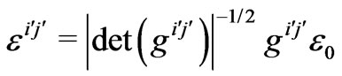 (1)
(1)
 (2)
(2)
where the metric is given by
 (3)
(3)
The Jacobian transformation matrix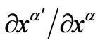
 , which is just the derivative of the transformed coordinates
  with respect to the original coordinates
 . And
. And 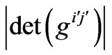 denotes the determinant of the matrix of
 .
.
Figure 1(a) is the model of structure. The model is composed of four triangles with distances of ,
, , c and d from the triangle center to every side, respectively. The four triangles divide the space into five regions indicated as
 ,
, ,
, ,
, and
and , respectively. The idea of the optical transformation is as follows: Firstly, the boundaries of
  and
and  are kept invariant. Secondly, the whole
  and
and  are compressed into region
 , and
, and  is stretched into the whole
  and
and . In order to achieve above ideas, the corresponding mapping (blue region) is,
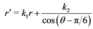 (4)
(4)
 (5)
(5)
 (6)
(6)
where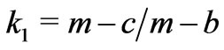 , and
, and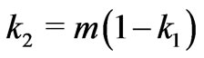 . If
. If  is within
  and
and ,
,  , which corresponds to compressed region; if
  is within
  and
and ,
,  , which corresponds to stretched region. The values of
  determine the ratio of compressed or stretched. The transformation matrix
  in the cartesian coordinate system can be deduced from Equation (3), which can be written as
 (7)
(7)
where 
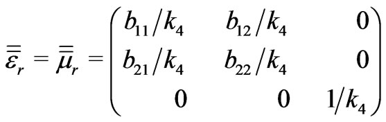
 According to Equations (1) and (2), the relative permittivity and permeability tensors of the material in the transformation regions can be expressed as
 (8)
(8)
where the parameters ,
,  ,
,  ,
,  . We note that the permittivity and permeability inside the transformation region are inhomogeneous and anisotropic. Although the material property tensors on the left and right hand sides of Equations (1) and (2) represent different material properties, both sets of tensor components are interpreted as components in a flat, Cartesian space. The form invariance of Maxwell’s equations insures that both interpretations lead to the same electromagnetic behavior [1]. Different from cloak design [1,2], the parameters of permittivity and permeability have no singular or very large values in or near the boundaries in the transformation region. Due to the symmetrical property of the transparent shell, the permittivity and permeability tensors of other three regions can be easily obtained in a similar way.
3. Simulation and Discussion
To study the properties of such radome structure, for simplicity, we consider the two dimensional (2D) transverse electric (TE) polarization incident waves (whose electric field is along z-direction). In the above design, the radome structure has nothing to do with frequencies. For numerical simulations, we choose a special frequency as 4 GHz. The numerical simulations are based on the finite element method.
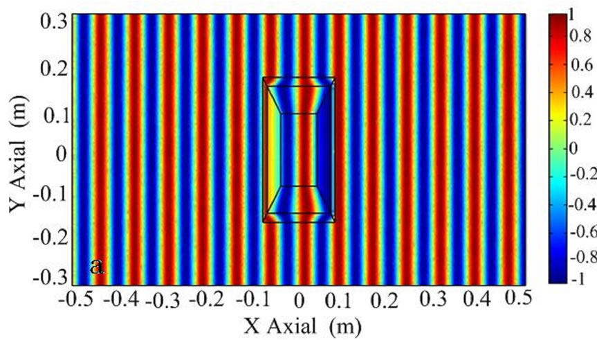
Firstly, we choose a = 0.06 m, b = 0.065 m, c = 0.075 m and d = 0.09 m. We assume that the incident plane wave is from left boundary of radome model. Figure 2(a) illustrates the distribution of EM field. Obviously, when the wave transmit into transformation region, there exist no reflective waves in the interface and the incident wave keeps invariant, while the EM wave is distorted in the transformation region (regions ). Moreover, when the wave transmit into region
 , the wave propagation status also keeps invariant, which means the structure is transparent for EM wave. After transmitting through the radome, the EM wave is also unaltered and propagate in the original direction, as if no radome exists.
The transformation optics structures apply to any oblique incident waves, since the design procedure does not depend on the incident angles. Secondly, we assume that cylinder wave is incident from the transparent model left. Figure 2(b) illustrates the distribution of EM field, where a line source with a current of  along z-direction is located at the (–0.3 m, 0). We can find that the cylinder wave is well recovered within
  when it pass through the transformation region. Thirdly, we assume that a line source with a current of
  along z-direction is located at coordinate origin, which is at the center of
 . Figure 2(c) shows the distribution of EM field in the transformation region and free space. We can find that the shape of the cylinder wave can also be recovered after passing through the transformation structure, as if the whole transformation does not exist. Because the transformation medium is matched with the surrounding
 (a)
(a) (b)
(b) (c)
(c)
Figure 2. The distribution of electric field EZ with a triangle structure. (a) An incident plane wave with the electric field polarized along the z direction from left to right; (b) an electric line source along the z direction located at (–0.3 m, 0); (c) an electric line source along the z direction at origin of coordinate.
medium, the wave propagates through the transformation medium without any reflections at the inner boundary of  and at outer boundary of
 . We also perform simulations with other frequencies, and obtain the same conclusions.
Using the same method, we can design radome with other shape. Figure 1(b) shows a rectangle radome. In the design, we divide the rectangle space into four sub-rectangle space with side length of ,
,  ,
,  and
and
 (a)
(a)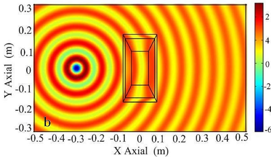 (b)
(b)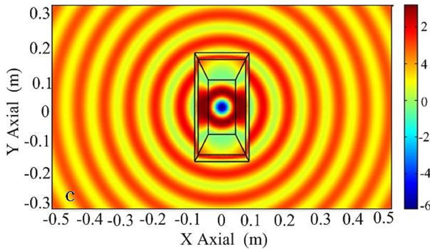 (c)
(c)
Figure 3. The distribution of electric field EZ with a rectangle transparent structure. (a) An incident plane wave with the electric field polarized along the z direction from left to right; (b) an electric line source along the z direction located at (–0.3 m, 0); (c) an electric line source along the z direction at origin of coordinate.
 in the x direction , and
 ,
,  ,
,  and
and  in the y direction respectively. The whole designed space is divided into five parts indicated as
 ,
, ,
, ,
, and
and  (Figure 1(b)), respectively. For simplicity, we assume that all rectangles have the same length-width ratio
 , and assume a1 = 0.08 m, b1 = 0.1 m, c1 = 0.14 m and d1 = 0.16 m. Figures 3(a) and (b) show the distribution of EM field for a incident plane wave and a cylinder wave, respectively. Although the wave is distorted within the transformation region, it is recovered the original propagation status when the wave passes over the transformation region. If a line source is located at the center of the s1 with a current of 10–3 Am–1 along z-direction, the spatial distribution of the electric field is shown in Figure 3(c). As can be seen, the original properties of the cylinder wave is recovered after the wave passes over the radome structure. Furthermore, there are also no reflections at the inner boundary of s1 and at outer boundary of s4.
Although two special shapes radomes have been designed above based on the transformation optics, the radomes with other shapes can also be designed, which can be matched different shapes antennas. Compared with traditional radomes, our transparent radomes can ensure radiation and receive efficiency of antenna owing to no reflections at the boundaries of radome. Therefore, the special structures can be one of good choices for radomes in the future.
4. Conclusions
In this paper, we have proposed and designed a kind of arbitrary radome structure basing on the idea of transformation optics. In the radome region, twice transformation are performed, one is compressing transformation, the other is stretching transformation. The theoretical analysis for a triangle transparent model and a rectangle transparent model are presented. Two dimensional finiteelement simulations are performed to confirm the theoretical results.
5. Acknowledgements
This work was supported by the National Science Foundation of China under Grant No. 3670156.
REFERENCES
- J. B. Pendry, D. Schurig and D. R. Smith, “Controlling electromagnetic fields,” Science, Vol. 312, No. 5781, 2006, pp. 1780-1782. doi:10.1126/science.1125907
- D. Schurig, J. B. Pendry and D. R. Smith, “Metamaterial Electromagnetic Cloak at Microwave Frequencies,” Optics Express, Vol. 14, No. 21, 2006, pp. 9794-9804. doi:10.1364/OE.14.009794
- S. A. Cummer, B.-I. Popa, D. Schurig, D. R. Smith and J. B. Pendry, “Full-Wave Simulations of Electromagnetic Cloaking Structures,” Physical Review E, Vol. 74, No. 3, 2006, pp. 036621-036626. doi:10.1103/PhysRevE.74.036621
- D. Schurig, J. J. Mock, B. J. Justice, S. A. Cummer, J. B. Pendry, A. F. Starr and D. R. Smith, “Metamaterial Electromagnetic Cloak at Microwave Frequencies,” Science, Vol. 314, No. 5810, 2006, pp. 977-980. doi:10.1126/science.1133628
- X. H. Zhang, H. Y. Chen, X. D. Luo and H. R. Ma, “Manipulating the Directivity of Antennas with Metamaterial,” Optics Express, Vol. 16, No. 15, 2008, pp. 10962-10967. doi:10.1364/OE.16.010962
- M. Rahm, D. A. Roberts, J. B. Pendry and D. R. Smith, “Transformation-Optical Design of Adaptive Beam Bends and Beam Expanders,” Optics Express, Vol. 16, No. 15, 2008, pp. 11555-11567. doi:10.1364/OE.16.011555
- L. Lin, W. Wang, J. H. Cui, C. L. Du and Xi. G. Luo, “Design of Electromagnetic Refractor and Phase Transformer Using Coordinate Transformation Theory,” Optics Express, Vol. 16, No. 10, 2008, pp. 6815-6821. doi:10.1364/OE.16.006815
- H. Ma, S. Qu, Z. Xu and J. Fu Wang, “General Method for Designing Wave Shape Transformers,” Optics Express, Vol. 16, No. 26, 2008, pp. 22072-22082. doi:10.1364/OE.16.022072
- W. X. Jiang, T. J. Cui, Q. Cheng, J. Y. Chin, X. M. Yang, R. Liu and D. R. Smith, “Design of Arbitrarily Shaped Concentrators Based on Conformally Optical Transformation of Nonuniform Rational B-Spline Surfaces,” Applied Physics Letters, Vol. 92, No. 26, 2008, pp. 264101-264103. doi:10.1063/1.2951485
- H. Y. Chen and C. T. Chan, “Transformation media that rotate electromagnetic fields,” pplied Physics Letters, Vol. 90, No. 24, 2007, pp. 241105-241107. doi:10.1063/1.2748302
- Y. T. Fang and S. L. He, “Transparent Structure Consisting of Metamaterial Layers and Matching Layers,” Physical Review A, Vol. 78, No. 2, 2008, pp. 023813-023818. doi:10.1103/PhysRevA.78.023813