Journal of Electromagnetic Analysis and Applications
Vol. 3 No. 10 (2011) , Article ID: 8142 , 7 pages DOI:10.4236/jemaa.2011.310063
Compact Metamaterial Microstrip Low-Pass Filter
![]()
1School of Electronic Engineering, KIIT University, Bhubaneswar, India; 2Electronic Science Department, Berhampur University, Bhanja Vihar, Berhampur, Orissa, India; 3Department of Electronics & Telecommunication Engineering, Jadavpur University, Kolkata, India.
Email: sudhakarsahu@yahoo.co.uk, r.k.mishra@ieee.org, drp_ju@yahoo.com
Received July 21st, 2011; revised August 22nd, 2011; accepted September 4th, 2011.
Keywords: Hex-Omega Structure, Microstrip Low-Pass Filter, Metamaterial, Sharp Cut-Off
ABSTRACT
Complimentary hexagonal-omega structures are used to design compact, low insertion loss (IL), low pass filter with sharp cut-off. It has been designed for improvement of roll-off performance based on both μ and ε negative property of the complimentary hex-omega structure while maintaining the filter pass-band performance. By properly designing and loading the hexagonal-omega structure in the ground of microstrip line not only improve the roll-off of the low pass filter, but also reduced the filter size. The simulated results indicate that the proposed filter achieves a flat pass band with no ripples as well as selectivity of 19.68 dB/GHz, corresponding to 5-unit cells hex-omega structures. This significantly exceeds the 5.6 dB/GHz selectivity of the conventional low pass filter design, due to sub-lambda dimensions of the hex-omega structure. A prototype filter implementing area is: 0.712 λg × 0.263 λg, λg being the guided wavelength at 3-dB cut-off frequency (fc). The proposed filter has a size smaller by 36.2%.
1. Introduction
In microwave communication systems, low-pass filters (LPF) are often an important component. Use of stepped impedance LPF and open stub LPF are common [1-4]. In the responses of such filters, the roll-off to cut-off is not sharp but gradual. Therefore, the rejection characteristic has limitations in such traditional LPF. This limitation can be improved by increasing the passband insertion loss (IL) by adding more number of sections. But this increases physical size, severely limiting any scope for miniaturization. In order to overcome these problems recently there has been a growing interest for the use of metamaterial [5] in the development of compact microwave components using printed circuit boards and MMIC technologies [6-11].
This communication proposes etching of hex-omega structure [12] in the ground of microstrip line to improve the selectivity of microwave low pass filter. A complimentary hexagonal omega structure in the ground plane produces a sharp rejection stop band in the vicinity of its resonance. By loading hex-omega structures in the ground of the conventional microstrip LPF, it is possible to realize a filter that shows no ripples in the pass band as well as exhibits a steep roll-off without compromising the circuit size.
2. Proposed Low-Pass Filter Design
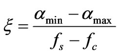
A design of maximally flat LPF with a cut-off frequency of 4.5 GHz, impedance of 50 Ω and at least 10 dB insertion loss at 5 GHz is taken up to demonstrate the utility of proposed structure (Figure 1). From design charts [13], the order of the filter that satisfied the specification was found to be N = 5. One of the important parameters for a low-pass filter is selectivity as defined in [14]
 (1)
(1)
where ξ is the selectivity in dB/GHz, αmax the 3 dB-attenuation point, αmin the 20 dB-attenuation point, fs the 20 dB stop-band frequency and fc the 3 dB cut-off frequency.
To add in extra functionality while sustaining the filter pass-band performance without increasing the size, Hexomega structures were etched into the ground plane (Figure 1). The aim of the hex-omega particles was to provide a stop-band characteristic near the vicinity of the 3 dB cut-off frequency, so as to improve the roll-off of the filter. Etching the hex-omega structure in the ground plane below the conductor strip ensures that the particle is excited properly. This is achieved by an electric field polarized in the axial direction of the hex-omega ring.
 (a)
(a) (b)
(b)
Figure 1. Topology of (a) conventional LPF (b) hex-omega structures etched in the ground plane (depicted in lightgray).
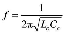
Around the resonant frequency, a deep stop band is introduced due to the presence of a negative effective permittivity. The dominant coupling mechanism between the line and the hex-omega structure is electric and this can be portrayed by a coupling capacitance which is given by the line capacitance corresponding to the line section occupied by the hex-omega structure [12]. The Hex-omega structure can be described as an LC resonant tank, the resonant frequency is
 (2)
(2)
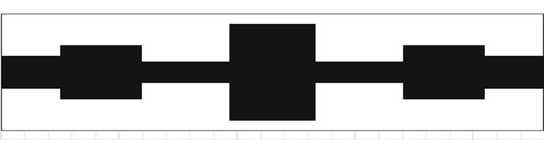
The geometry of the unit cell structure is as depicted in Figure 2. To improve the roll-off of the low-pass filter, a set of such hex-omega structures with resonant frequency near the conventional low-pass filter cut-off frequency fc are required.
3. Simulation and Verification of Metamaterial
A hex-omega structure with frequency 4.5 GHz is simulated (Figure 3) to verify the existence of negative effec-

Figure 2. Hex omega unit cell structure.

Figure 3. Simulation model of the unit cell with the polarization and propagation direction.
tive permittivity. Figures 4 and 5 show respectively the simulated transmission (S21) and reflection (S11) parameters for this structure. The full wave simulated scattering parameters were used to extract the complex effective permittivity and permeability of a transmission line [15]. When the wavelength is much larger than the dimensions of the constituent scattering elements that compose the left-handed media, the effective medium theory is applicable. Applying this theory an inhomogeneous left handed media can be substituted by an equivalent structure with homogeneously filled effective permeability μeff and permittivity εeff, provided the fields in the equivalent structure are equal to the mean fields in the original structure. An effectively homogeneous structure is a structure whose structural average size ‘a’ is much smaller than the guided wavelength λg. Therefore this average cell size should be at least smaller than a quarter wavelength, a < λg/4. The condition of a = λg/4 will be referred to as the effective homogeneity limit, to ensure that refractive phenomenon will dominate over scattering or diffracting phenomena when a wave propagates inside the meta-material medium.
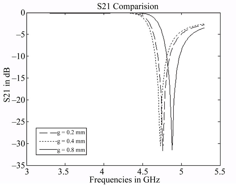
Figure 4. Simulated S21 results of the hex-omega structures for different gaps.
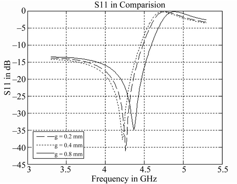
Figure 5. Simulated S11 results of the hex-omega.
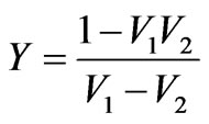
S-parameters retrieval technique is useful in obtaining the material parameters, when analytical techniques become increasingly difficult to apply (e.g. Scattering object has complex geometry). This procedure extracts the effective permittivity, effective permeability, index of refraction by inverting the reflection-transmission results considering the metamaterial as a homogeneous effective medium. S-parameters retrieval provides complete information on the material parameters of the sample in a direct manner. S-parameters measurement and retrieval can form the basis of a semi automated metamaterial characterization procedure. To extract effective medium parameter from the normal incidence scattering parameter data, the Nicolson-Ross-Weir (NRW) approach [16-19] and the corrections [17] were implemented. The NRW approach begins by introducing the composite terms.
 (3)
(3)
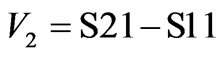 (4)
(4)
The effective permeability and permittivity are given by
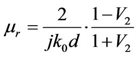 (5)
(5)
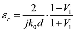 (6)
(6)
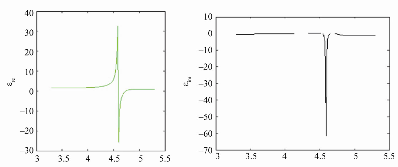
From the simulated reflection-transmission result of hex-omega structure, the real parts of effective permeability Re (µr) and effective permittivity Re (εr) at different frequencies are obtained by applying Equations (3)-(6). It is seen that Re (εr) is negative (Figure 6(a)) for frequencies between 4.0 - 4.8 GHz, confirming that the response is below the plasma frequency (ωp). It is also evident from the graph that the Re (µr) goes through a resonance at 4.0 GHz and achieves the first negative value at this point. The real part of µr remains negative (Figure 6(b)) up to 4.8 GHz. Thus the overlap region of negative values for Re (µr) and Re (εr) lies in the 4.0 - 4.8 GHz band. So a negative refractive index n can be expected in this region.
The index of refraction (n) is calculated from the sparameter data using the following formulae
 (7)
(7)
 (8)
(8)
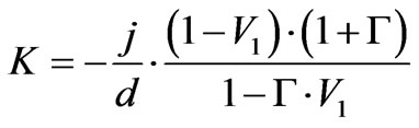 (9)
(9)
 (10)
(10)
where K0 is the free space wave length, K is complex wave number and n is index of refraction.
Figure 6(c) shows that the real part of index of refraction is negative over the frequency range 4.0 - 4.8 GHz. So the assumption made from the Re (µr) and Re (εr) curve it is proved to be correct. Hence, it can be concluded that index of refraction is also negative when effective permittivity and permeability are negative. Thus it indicates that for this frequency range the Hex-Omega structure is left handed.
4. Simulated and Experimental Results
To obtain good electrical performances from the proposed filters, key design parameters were tuned and optimized using advanced 3D EM simulation tools based on finite element method. The simulated results for different numbers of cells are shown in Figures 7 and 8. From Figure 7 it is observed that the cut-off becomes sharper with hex-omega structure than the conventional structure. Also, it is observed that as the number of hex-omega increases, the roll-off to the cut-off frequency becomes sharper as predicted earlier. The Figure 8 strengthens this claim, as it shows that there is good matching in the pass-band with hex-omega structure (s) than the conventional structure. The Figure 9 shows the group delay. It is observed that in the pass-band the group delay remains almost constant, whereas beyond the pass-band there is sharp rise in group delay. The negative phase velocity in LHM material compensates the delay in the pass-band, which results in such a behavior. This property indicates that the proposed filter can be used as a Zero-delay filter and enhance signal integrity.
The prototypes of the proposed LPF were fabricated using Rogers RT/Duroid 5870 (εr = 2.4, thickness = 1.6 mm) using standard photo etching techniques (Figures 10 and 11). An Agilent 8510C vector network analyzer was used to measure the response of the proposed filter and the results are shown in Figures 12-15.
The measured response for the conventional low-pass filter shows a low-pass characteristic with a 3 dB cut-off frequency of 2.9 GHz. The insertion loss reaches 10dB at 3.2 GHz and 40dB at 4.5 GHz and the measured roll-off rate of the conventional filter is 23.125 dB/GHz. It can be seen that the scattering parameters for the low-pass filter incorporating hex-omega particles, illustrate a much steeper roll-off than the conventional one. The filter acquires an 3 dB cut-off at 3 GHz and 40 dB attenuation at 4.88 GHz and hence the roll-off rate is19.68 dB/GHz for 5-unit cells hex-omega structures. It is also evident that
 (a)
(a)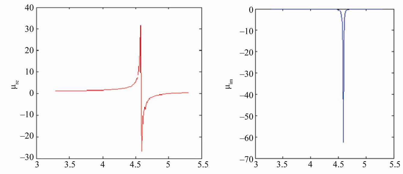 (b)
(b)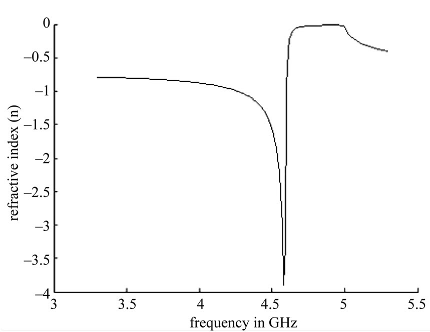 (c)
(c)
Figure 6. Simulated response and the extracted real and imaginary. (a) εeff;(b) μeff; and (c) refractive index, for a hex-omega structure incorporated in microstrip technology.
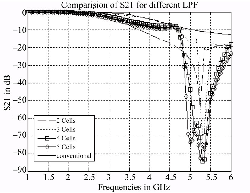
Figure 7. Simulated S21 results of low-pass filter with 2- cells, 3-cells, 4-cells and 5-cells hex-omega structure etched into the ground plane.
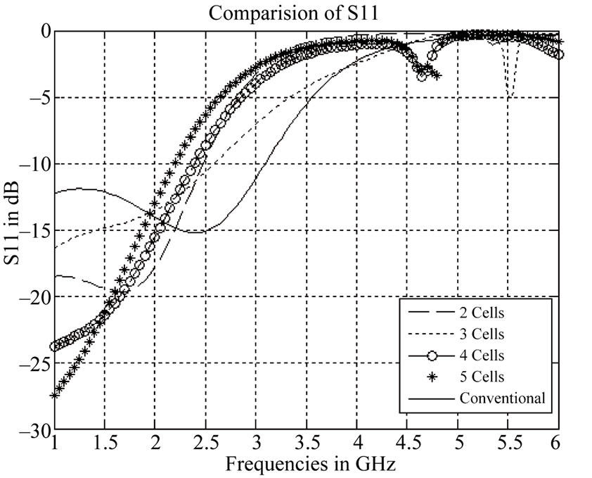
Figure 8. Simulated S11 results of low-pass filter with 2- cells, 3-cells, 4-cells and 5-cells hex-omega structure etched into the ground plane.
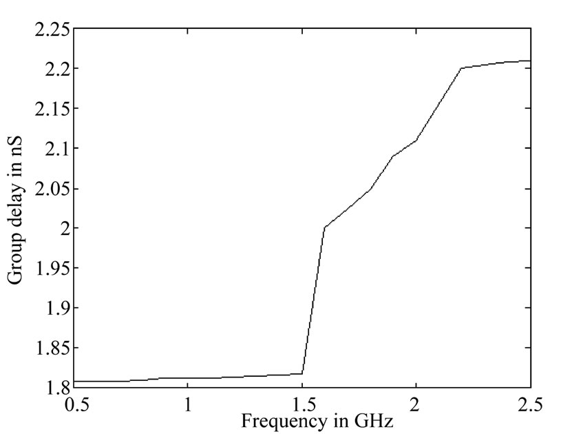
Figure 9. Simulated group delay variation.
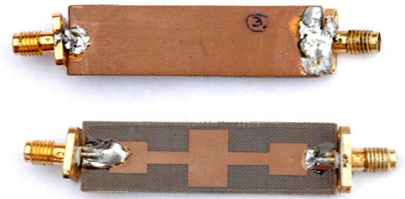
Figure 10. Picture of fabricated conventional maximally flat. (a) bottom & (b) top of low-pass filter.
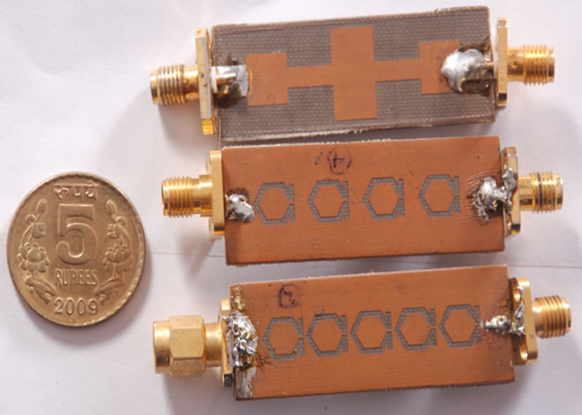
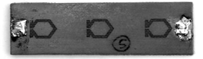
Figure 11. Fabricated proposed low pass filter with (a) 4 hex-omega structures; (b) 5 hex-omega & (c) 3 hex-omega structure etched into the ground plane.

Figure 12. Measured S21 response for conventional Low pass filter.
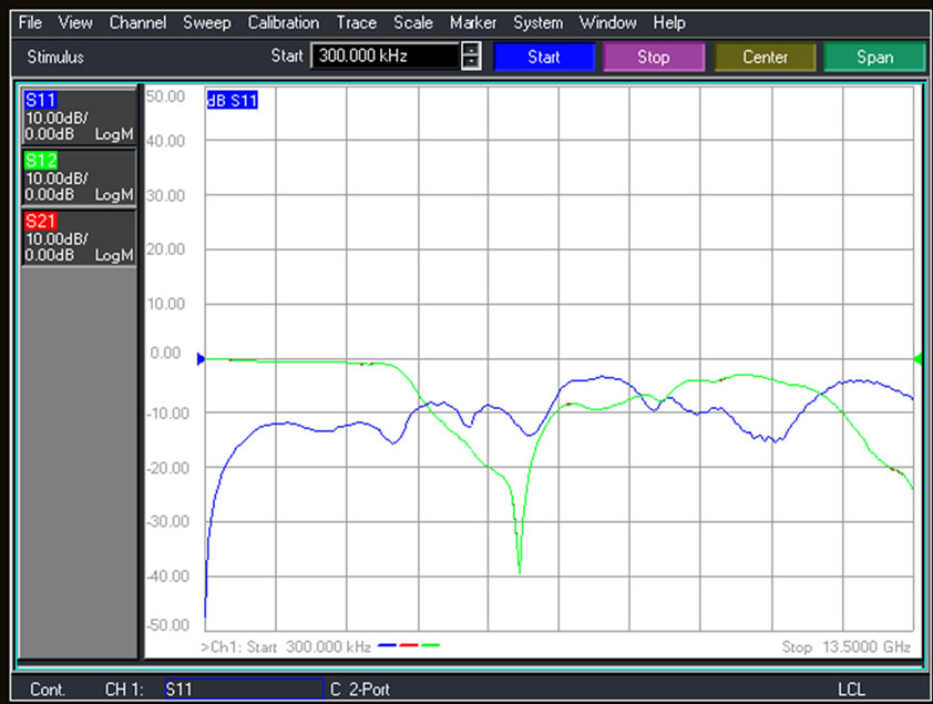
Figure 13. Measured S21&S11 response for low-pass filter with 5 hex-omega particles etched into the ground plane.
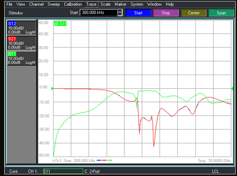
Figure 14. Measured S21&S11 response for the proposed low-pass filter with 4 hex-omega particles etched into the ground plane.
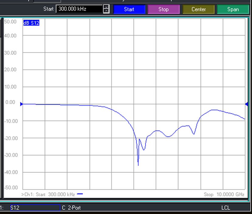
Figure 15. Measured S21 response for the proposed low-pass filter with 3 hex-omega particles etched into the ground.
incorporating hex-omega structures into a low-pass filter has not degraded pass-band performance. The overall area for the conventional low-pass filter is 782 mm² whereas the modified filter consumes an area of 499 mm², showing 36.2% reduction in size. The reason for the reduction in size of the proposed filter is due to subwavelength dimensions of the hex-omega structure and frequency dispersion [7]. The maximum group delay variation in the passband is within 2.2 ns.
5. Conclusions
This paper proposed and evaluated the performances of a planar maximally flat low-pass filter (LPF) using the complementary hex-omega structures in the ground plane. A size reduction of about 36.2% of the filter has been achieved. The measured data show that the selectivity has been improved by 71.54% (for 5-cells). Other advantages of the proposed filter includes: improved selectivity, compactness, low passband insertion loss, ease of fabrication (as no via holes or lumped elements are required), improved signal integrity, etc. The stop-band characteristic of a unit cell hex-omega structure was investigated.
6. Acknowledgements
The authors would like to thank Prof. Ajit Kumar Panda, DEAN, NIST, Berhampur, Odisha, India for generously providing the Lab facilities available at NIST under DST FIST & TIFAC-CORE programs.
REFERENCES
- D. Ahn, J.-S. Kim, C.-S. Kim, J. Qian and T. Itoh, “A Design of the Low-Pass Filter Using the Novel Microstrip Defected Ground Structure,” IEEE Transactions on Microwave Theory and Techniques, Vol. 49, No. 1, 2001, pp. 86-91. doi:10.1109/22.899965
- J. Garcia-Garcia, F. F. Martin, J. Bonache, et al., “Stepped-Impedance Low Pass Filter with Spurious Pass Band Suppression,” Electronic Letter, Vol. 40, No. 14, 2004, pp. 881-883. doi:10.1049/el:20040560
- J. W. Sheen, “Compact semi-Lumped Low-Pass Filter for Harmonics and Spurious Suppression,’’ IEEE Microwave Wireless Component Letter, Vol. 10, No. 3, 2000, pp. 92- 93.
- W. H. Tu and K. Chang, “Compact Microstrip Low-Pass Filter with Sharp-Rejection,” IEEE Microwave Wireless Component Letter, Vol. 15, No. 6, 2005, pp. 404-406. doi:10.1109/LMWC.2005.850479
- V. G. Veselago, “The Electrodynamics of Substances with Simultaneous Negative Values of ε and μ,” Soviet Physics Uspekhi, Vol. 10, No. 4, 1968, pp. 509-514. doi:10.1070/PU1968v010n04ABEH003699
- J. Bonache, M. Gil, I. Gil, J. Garcia-Garcia and F. Martin, “On the Electrical Characteristics of Complementary Metamaterial Resonators,” IEEE Microwave and Wireless Components Letters, Vol. 16, No. 10, 2006, pp. 543- 545. doi:10.1109/LMWC.2006.882400
- J. Garcia-Garcia, F. F. Martin, J. Bonache, et al., ‘Microwave Filters with Improved Stopband Based on SubWavelength Resonators,” Microwave and Optical Technology Letter, Vol. 46, No. 3, 2005, pp. 283-285.
- J. B. Pendry, A. J. Holden, D. J. Robbins, R. Marques, F. Martin and M. Sorolla, ‘Effective Negative-ε Stop-Band Microstrip Lines Based on Complementary Split-Ring Resonators,” IEEE Microwave Wireless Component Letter, Vol. 14, No. 6, 2004, pp. 280-282. doi:10.1109/LMWC.2004.828029
- J. D. Baena, J. J. Bonache, F. F. Martin, R. Marques, et al., ‘Equivalent–Circuit Models for Split Ring Resonators Coupled to Planar Transmission Lines,” IEEE Transaction on Microwave Theory and Techniques, Vol. 53, No. 4, 2005, pp. 1451-1461. doi:10.1109/TMTT.2005.845211
- N. Engheta and R. W. Ziolkowsky, “Metamaterial: Physics and Engineering Explorations,” Wiley, Hoboken, 2006.
- C. Caloz and T. Itoz, “Electromagnetic Metamaterials: Transmission Line Theory and Microwave Applications,” Wiley, Hoboken, 2006.
- S. Sahu, R. K. Mishra and D. R. Poddar, “Design of DNG Metamaterial Using Hexagonal Omega Structure,” National Symposium on Antenna and Propagation, Cochin, 29-31December 2008.
- D. M. Pozar, “Microwave Engineering,” Wiley, Hoboken, 2005.
- J. L. Li, S. W. Qu and Q. Xue, “Compact Microstrip Lowpass Filter with Sharp Roll-Off and Wide StopBand,” IEE Electronics Letters, Vol. 45, No. 2, 2009, pp. 110-111. doi:10.1049/el:20093246
- R. W. Ziolkowski, “Design, Fabrication, and Testing of Double Negative Metamaterials,” IEEE Transactions on Antenna and Propagation, Vol. 51, No. 7, 2003, pp. 1516-1529. doi:10.1109/TAP.2003.813622
- A. M. Nicolson and G. F. Ross, “Measurement of the Intrinsic Properties of Materials by Time Domain Techniques,” IEEE Transactions on Instrumentation and Measurement, Vol. 19, No. 4, 1970, pp. 377-382. doi:10.1109/TIM.1970.4313932
- W. B. Weir, “Automatic Measurement of Complex Dielectric Constant and permeability at Microwave Frequencies,” Proceedings of the IEEE, Vol. 62, No. 1, 1974, pp. 33-36. doi:10.1109/PROC.1974.9382
- P. K. Kadaba, “Simultaneous Measurement of Complex Permittivity and Permeability at Microwave Frequencies,” IEEE Transaction on Instrumentation and Measurement, Vol. 33, No. 4, 1984, pp. 336-340. doi:10.1109/TIM.1984.4315236
- D. K. Ghodgaonkar, V. V. Varadan and V. K. Varadan, “Free-Space Measurement of Complex Permittivity and Permeability at Microwave Frequencies,” IEEE Transaction on Instrumentation and Measurement, Vol. 39, No. 2, 1990, pp. 387-394. doi:10.1109/19.52520
- J. S. Hong and M. J. Lancaster, “Microstrip Filters for RF/Microwave Applications,” Wiley, New York, 2001. doi:10.1002/0471221619
- J. Wang, L. J. Xu, S. Zhao, Y. X. Guo and W. Wu, “Compact Quasi-Elliptic Microstrip Lowpass Filter with Wide Stopband,” IEE Electronics Letters, Vol. 46, No. 20, 2010, pp. 1384-1385.
- C. W. Tang and M. G. Chen, “Design of Microstrip Lowpass Filters with Wide Stopband and High Attenuation,” IEE Electronics Letters, Vol. 46, No. 21, 2010, pp. 1445-1447. doi:10.1049/el.2010.2147
- C.-W. Tang and S.-C. Yang, “Employing Complementary Split-Ring Resonators for the Wide Stopband Microstrip Lowpass Filter Design,” Microwave and Optical Technology Letters, Vol. 52, No. 11, 2010, pp. 2592-2594. doi:10.1002/mop.25541