Journal of Electromagnetic Analysis and Applications
Vol. 3 No. 7 (2011) , Article ID: 5906 , 6 pages DOI:10.4236/jemaa.2011.37042
Electromagnetic Wave Propagation into Fresh Water
![]()
Department of Electrical and Computer Engineering, Florida International University, Miami, USA.
Email: shan.jiang1@fiu.edu, georgako@fiu.edu
Received April 20th, 2011; revised May 21st, 2011; accepted June 2nd, 2011.
Keywords: Wireless communications, Propagation, Fresh water, Optimum frequency
ABSTRACT
Wireless communications from air to fresh water are studied here. Our analysis relies on plane wave propagation models. Specifically, the transmission loss and propagation loss of RF waves penetrating into fresh water are calculated for various propagation depths. Even though RF wireless communications are not well suited for seawater due to its high attenuation, our paper illustrates that RF communications from air to fresh water are possible. Finally, this work derives the optimum frequencies, which provide minimum attenuation and maximum propagation depth, for RF communications from air to fresh water.
1. Introduction
Underwater communications have attracted significant interest in recent years since they have a wide range of applications including coastline protection, underwater environmental observation for exploration, off-shore oil/ gas field monitoring, oceanographic data collection, autonomous underwater vehicles (AUVs) and remotely operated vehicles (ROVs), etc., [1]. Reliable data monitoring and transmission in shallow fresh water (e.g., rivers and lakes) have also received growing interest since they can provide information that is crucial for the local economies as well as the environment. Traditionally, underwater communications have been done through acoustic and optical systems that have certain advantages and disadvantages. For example, acoustic communications are widely used in underwater environment but their performance in shallow waters is severely affected by multipath propagation. Also, the channel latency caused by the low propagation velocity in water is another limitation of acoustic communications. On the contrary, laser based optical systems have significantly higher propagation speed than underwater acoustic waves. However, strong backscattering caused by suspended particles in water always limits the application of optical systems to very short distances.
Electromagnetic (EM) waves in the RF range can also be used for underwater wireless communication systems. The velocity of EM waves in water is more than 4 orders faster than acoustic waves so the channel latency is greatly reduced. In addition, EM waves are less sensitive than acoustic waves to reflection and refraction effects in shallow water. Moreover, suspended particles have very little impact on EM waves. Few underwater communication systems based on EM waves have been proposed before [2,3].
The primary limitation of EM wave propagation in water is the high attenuation due to the conductivity of water. For example, it has been shown in [4] that conventional RF propagation works poorly in seawater due to the losses caused by the high conductivity of seawater (typically, 4 S/m). However, fresh water has a typical conductivity of only 0.01 S/m, which is 400 times less than the typical conductivity of seawater. Therefore, EM wave propagation can be more efficient in fresh water than in seawater.
This work focuses on the analysis of electromagnetic waves penetrating from air to fresh water. The following two types of losses are analyzed: 1) the transmission loss that is due to reflection at the air-water interface, and 2) the propagation loss inside the water due to its material properties. The electromagnetic properties of fresh water are modeled using the Debye model. Also, the effects of the incidence angle as well as the polarization are examined and an optimum frequency range is identified for RF air-to-water communications to minimize the power loss.
2. Plane Wave Model
In this section, we model a plane wave impinging on an air-water interface assuming the depth of water is infinite (see Figure 1). For such a plane wave penetrating the fresh water, the total power loss is the sum of the transmission loss and propagation loss. Our analytical formulations describe both loss mechanisms.
2.1. Power Attenuation for Normal Incidence
We formulate analytical equations to calculate the transmission loss and propagation loss for the scenario of Figure 1. The incident power is written as:
 (1)
(1)
where Ei is the incident electric field and 
stands for the intrinsic impedance of air. Similarly, the transmitted power in water is written as:
 (2)
(2)
where Et is the transmitted electric field, and
 is the intrinsic impedance of water, where
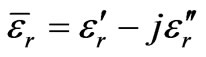 stands for the relative complex permittivity of fresh water [5].
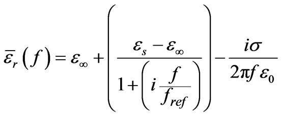
The complex frequency dependent dielectric permittivity  of water is commonly described with the Debye model as:
 (3)
(3)
where εs and ε∞ are the real relative permittivity at low and high frequencies, respectively, fref is the relaxation frequency, σ is the conductivity of water, and ε0 is the dielectric permittivity of free space. Table 1 shows the Debye parameters of water reported in [5].
Further, the transmitted power in (2) can also be expressed as follows:
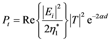 (4)
(4)
where T is the transmission coefficient given by:
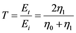 (5)
(5)
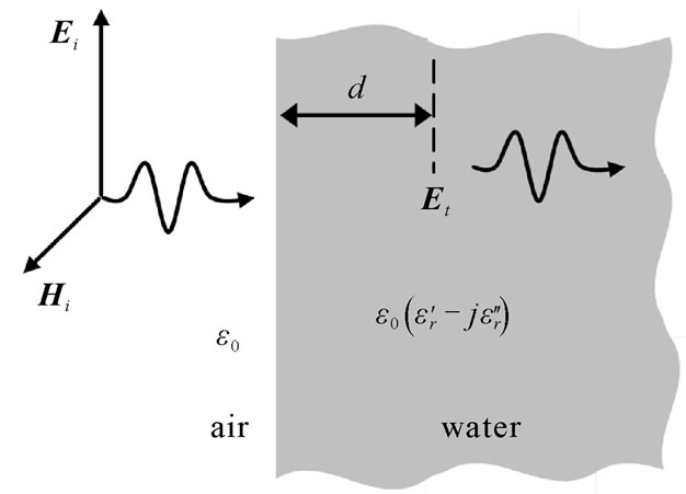
Figure 1. Plane wave penetrating fresh water at normal incidence.
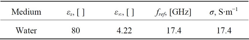
Table 1. Debye parameters of water [5].
Then, the transmission loss describing the power loss caused by the wave reflection at the air-water interface can be calculated in dB as follows:
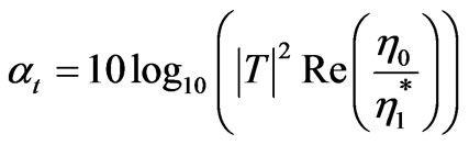 (6)
(6)
When calculating the propagation loss inside water, the attenuation α [6], is given by (7),
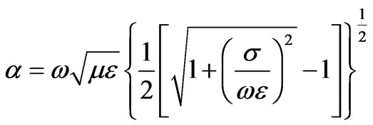 (7)
(7)
and the propagation loss in dB is defined as shown below:
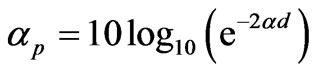 (8)
(8)
where d is the depth of propagation inside water.
Therefore, the total loss of the normal incidence is written in (9),
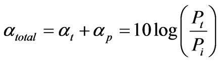 (9)
(9)
and it depends on the complex permittivity of water and the depth of propagation.
2.2. Power Attenuation for Oblique Incidence
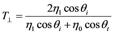
To examine transmissions at oblique incidence angles for a general wave polarization, it is convenient to decompose the electric field into perpendicular and parallel components and analyze them separately. The transmission coefficient for parallel and perpendicular polarization is given by:
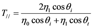 (10)
(10)
 (11)
(11)
where θi is the angle of incidence and θt is the angle of transmission, given by Snell’s law of refraction [6] as
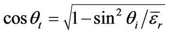 .
.
The transmission loss for oblique incidence can be written as follows using (6) and (10)-(11):
 (12)
(12)
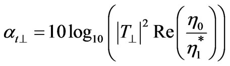 (13)
(13)
The propagation loss for oblique incidence is written as:
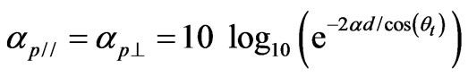 (14)
(14)
Therefore, the total loss of the oblique incidence is given by
 (15)
(15)
 (16)
(16)
and it depends on the complex permittivity of water as well as the angle of incidence.
3. Results
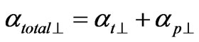
The transmission loss as well as propagation loss for a plane wave propagating from air to water is analyzed in the frequency range of 23 kHz to 1 GHz for normal incidence. This frequency range includes frequencies from the VLF (used in submarine communications) to the UHF band. Various propagation depths are considered since the propagation loss increases as the depth increases. In addition, the transmission loss remains the same for all propagation depths.
Figure 2 illustrates that the transmission loss decreases dramatically as the frequency increases from 23 kHz to 10 MHz, and then remains almost constant for frequencies higher than 10 MHz.
The propagation loss (see Figure 3) exhibits an opposite trend when compared to the trend of the transmission loss. Specifically, Figure 3(a) shows that it increases slowly for frequencies up to 100 MHz and then increases dramatically for higher frequencies (especially for frequencies around 1 GHz).
Furthermore, the transmission loss and propagation loss are added together to obtain the total power loss for
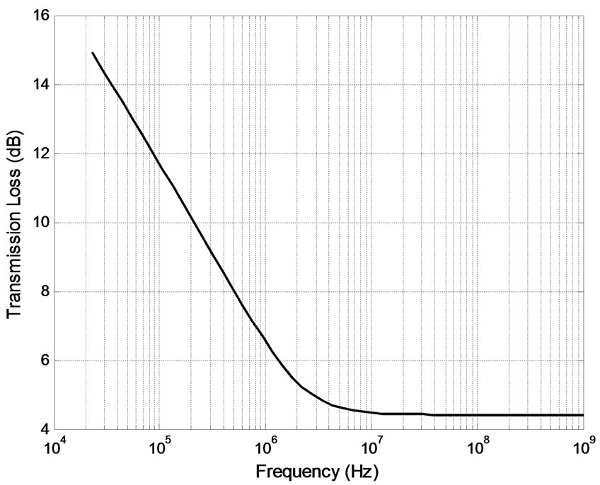
Figure 2. Transmission loss for normal incidence.
 (a)
(a) (b)
(b)
Figure 3. Propagation loss for normal incidence at different propagation depths, d: (a) shallow and (b) deep.
the air-to-water propagation (see Figure 1) and are plotted in Figure 4. As expected, due to the reverse variations of the transmission and propagation losses, an optimum frequency range exists for shallow propagation depths. In this optimum frequency range, there is significantly smaller power loss. For example, in Figure 4(a), the total loss in 3 - 100 MHz frequency range for a depth of 1 m is 10 dB to 45 dB smaller than the loss at the lowest and highest frequencies of our frequency range. Therefore, according to Figure 4(a) there is a range of optimum frequencies that exhibit minimum losses when a wave propagates from air to shallow fresh water depths. This range of frequencies can improve RF communications with underwater vehicles, or devices. Potential applications that can benefit from operating in the optimum frequency range include the following: 1)
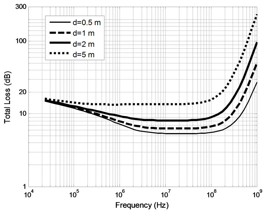 (a)
(a)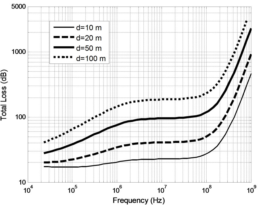 (b)
(b)
Figure 4. Total attenuation for normal incidence at different propagation depths, d: (a) shallow and (b) deep.
communications with underwater robots [7], 2) RFID based shore erosion detection [8], 3) water quality monitoring of bodies of fresh water (e.g., temperature, pH, etc.), such as, artificial lakes, swimming pools, and water tanks, using wireless underwater sensors.
Figure 4(b) also illustrates that the total loss monotonically increases when the propagation depth is larger than 10 m, thereby providing no optimum frequency range. This happens because the transmission loss is the same for different propagation depths whereas the propagation loss increases as the propagation depth becomes larger. Therefore, as the depth increases it reaches a value for which the propagation loss becomes larger than the transmission loss. Therefore, the optimum frequency range exists only for small propagation depths (less than 5 m).
Following similar steps to the normal incidence case of water half-space, the total attenuation for oblique incidence is calculated across incident angles from 0 to 89 degrees for both parallel and perpendicular polarization cases. Figure 5 illustrates that normal incidence has the least power loss for fixed frequency and propagation depth, since the total attenuation increases along with the incident angle for both polarization cases. For example, for parallel polarization, the total loss increases slowly for angles up to 80 degrees, but increases dramatically for larger incident angles.
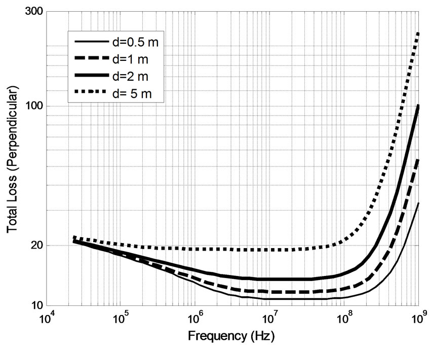
Also, the average total loss across all incident angles ranging from 0 to 89 degrees is calculated for different propagation depths. Figure 6 plots the average total loss versus frequency for both parallel and perpendicular polarization cases. It can be concluded that the average total loss for an oblique incident plane wave is larger than the normal incidence case, but with similar trend. For example, for a propagation depth of 1 m, the average total loss
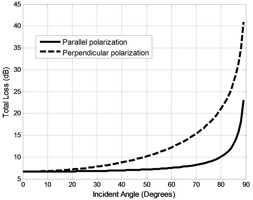
Figure 5. Total attenuation for oblique incidence when f = 100 MHz, d = 1 m.
 (a)
(a)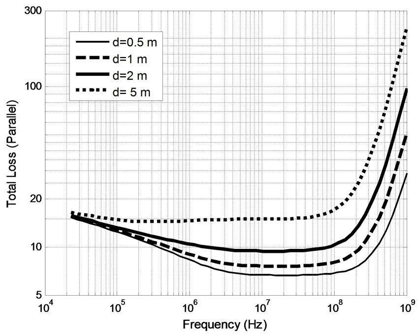 (b)
(b)
Figure 6. Average total loss across all incidence angles from 0 to 89 degrees at different depths for: (a) parallel polarization and (b) perpendicular polarization.
for perpendicular polarization (see Figure 6(b)) in the 3 MHz to 100 MHz frequency range is about 5 dB more than the total loss for normal incidence (see Figure 4(a)). From the results of Figure 6 for the oblique incidence case we observe that there is also an optimum frequency range similar to the one we identified for the normal incidence case.
4. Conclusions
A plane wave model for the air-to-water interface has been used to calculate the transmission loss, propagation loss as well as the total loss at various incident angles. The values of these losses depend on the electromagnetic properties of water, frequency, incidence angle and the propagation depth. For such air-to-water communications, an optimum frequency range (3 - 100 MHz) was identified when the plane wave propagates to depths less than 5 m. In this optimum frequency range, the wave experiences significantly smaller losses than the losses at the lowest and highest frequencies of our analysis. Specifically, this frequency range includes the bands of shortwave radio (3 - 30 MHz), VHF TV (54 - 72 MHz, 76 - 88 MHz), parts of FM (88 - 108 MHz) and US military VHF-FM (30 - 88 MHz). Therefore, various communications systems can benefit from using the optimum operation frequencies that we identified here. Also, wireless power harvesting by wireless sensors can be significantly enhanced if it is performed inside the 3 - 100 MHz range.
It should be also pointed out, that practical compact antenna designs can be developed in the optimum frequency range of 3 - 100 MHz for underwater devices due to the large permittivity of water (εr = 81). For example, a half-wavelength loop antenna operating at 100 MHz inside fresh water has a diameter of only 5.3 cm. Therefore, the optimum frequency range can be used in practical underwater communication systems and it will provide minimum losses for shallow propagation depths.
5. Acknowledgements
This work was supported by the Dissertation Year Fellowship provided by Florida International University’s Graduate School.
REFERENCES
- L. Liu, S. Zhou and J. Cui, “Prospects and Problems of Wireless Communication for Underwater Sensor Networks,” Wiley WCMC Special Issue on Underwater Sensor Networks (Invited), 2008.
- J. H. Goh, A. Shaw, A. I. Al-Shanmma’a, “Underwater Wireless Communication System,” Journal of Physics, Conference Series 178, 2009.
- A. I. Al-Shamma’a, A. Shaw and S. Saman, “Propagation of Electromagnetic Waves at MHz Frequencies through Seawater,” IEEE Transactions on Antennas and Propation, Vol. 52, No. 11, November 2004, pp. 2843-2849.
- S. Bogie, “Conduction and Magnetic Signaling in the Sea,” Radio Electronic Engineering, Vol. 42, No. 10, 1972, pp. 447-452. doi:10.1049/ree.1972.0076
- J. B. Hasted, “Aqueous Dielectrics,” Chapman and Hall, New York, 1973.
- C. A. Balanis, “Advanced Engineering Electromagnetics,” John Wiley & Sons, New York, 1989.
- T. Shaneyfelt, M. A. Joordens, K. Nagothu and M. Jamshidi, “RF Communication between Surface and Underwater Robotic Swarms,” Automation Congress, Hawaii, 9 December 2008.
- G. Benelli, A. Pozzebon and G. Ragseo, “An RFID Based System for the Underwater Tracking of Pebbles on Artificial Coarse Beaches,” IEEE 2009 3rd International Conference on Sensor Technologies and Applications, Athens, 18-23 June 2009, pp. 294-200.