Journal of Electromagnetic Analysis and Applications
Vol. 2 No. 5 (2010) , Article ID: 1913 , 10 pages DOI:10.4236/jemaa.2010.25037
First Evidence of Surface SH-Wave Propagation in Cubic Piezomagnetics
![]()
International Institute of Zakharenko Waves (IIZWs), Krasnoyarsk, Russia.
Email: aazaaz@inbox.ru
Received January 25th, 2010; revised March 18th, 2010; accepted March 25th, 2010.
Keywords: piezomagnetic cubic monocrystals, Galfenol and Terfenol-D, ultrasonic surface Zakharenko waves
ABSTRACT
This theoretical work provides with results of characteristics calculation of the ultrasonic surface Zakharenko waves (USZWs) existing in piezomagnetic cubic monocrystals of class m3m that can be readily used for non-destructive testing. The piezomagnetic waves propagate in direction [101] corresponding to relatively easy magnetization for the following piezomagnetics: Galfenol, Terfenol-D, and CoFe2O4 with cubic structures. The phase velocities of the USZW-waves and the coefficient of magnetomechanical coupling (CMMC) K2 were calculated for the crystals. It was found that the coefficient K2 for piezomagnetics with Km2 > 1/3 and Km2 >> 1/3 is about 8% to 9%, where K2 = 2 (VUSZW,o – VUSZW,c)/VUSZW,o and Km2 = h2/(Cμ). Knowledge of piezomagnetic properties of cubic crystals makes possible the use of them in new products utilizing the phenomenon called the magnetoelectric effect. Also, this study is useful for possible application of cubic piezomagnetics in composite structures consisting of piezoelectric and (or) piezomagnetic materials and in the microwave technology. This broadens choice of possible piezomagnetic materials for utilization in various technical devices.
1. Introduction
Ferroic materials can display a spontaneous magnetization (ferromagnetic), polarization (ferroelectric) and strain (ferroelastic, shape memory alloy). Materials possessing two “ferro” properties simultaneously are called “biferroics”. There are three kinds of biferroic materials: electroelastic, magnetoelastic, and magnetoelectric materials. The magnetoelectric materials (composites) can simultaneously possess ferromagnetic and ferroelectric properties. Composite materials or structures consisting of piezoelectric and piezomagnetic phases are able to facilitate the conversion of energy between electric and magnetic fields. Such phenomenon is called magnetoelectric (ME) effect. The ME effect of the composites was first reported by van Suchtelen [1]. The ME effect was then studied by van den Boomgaard [2], van Run et al. [3], and van den Boomgaard et al. [4] for BaTiO3/ CoFe2O4 composites. Possible applications of ME materials include magnetic-electric energy converting components; solid state non-volatile memory, multi-state memory, which can find application in quantum computing area; and electrical/optical polarization components, which can find applications in communication, light computing, and solid state memories based on spintronics [5,6]. Also, this research topic can be found in a recent review paper [7] by Fiebig. Note that the ME effect was originally predicted by P. Curie [8] in 1894.
Surface acoustic wave (SAW) devices are widely used in numerous branches of science and technology and their investigation especially in the case of interconnected physical fields is an important and actively developing branch of research and applications. About 120 years ago the first type of SAW was described by Lord Rayleigh [9] in connection with the problem of earthquakes. Bleustein [10] and Gulyaev [11] theoretically predicted that a pure shear-horizontal (SH) surface wave can be guided by the free surface of a piezoelectric half-space. Later, Maerfeld and Tournois [12] investigated SH acoustic waves guided by the interface of two half-spaces, and Danicki [13] described the acoustic waves which can be guided by an embedded conducting plane in the electro-elastic materials of class 6 mm. It is thought that the simplest type of SH-SAW represents Love waves [14] in layered systems, consisting of an isotropic layer and an isotropic substrate. Recent developments in physics and technology made possible to construct new magneto-electro-elastic materials which demonstrate interconnection between magnetic, electricand elastic fields [15,16]. When the electric field was connected with the elastic one (piezoelectric materials) it brought up new and unexpected possibilities for science and technology. Connecting the magnetic field with the electric and elastic ones in magneto-electro-elastic materials suggests a range of new possibilities. Alshits et al. [17] conducted a qualitative investigation on the existence of surface waves in half-infinite anisotropic elastic media with piezoelectric, piezomagnetic, and ME effects. Soh and Liu [18] gave the existence conditions of interfacial SH-waves in a piezoelectric/piezomagnetic bi-material. Although much attention has been recently concentrated on magneto-electro-elastic materials and several dynamic problems have been solved by Hu and Li [19], Li [20], Chen, et al., [21], etc., the investigation of SAW propagation in transversely isotropic magneto-electro-elastic materials [22-25] of class 6 mm is currently an open actual subject. In addition to the transversely isotropic materials there are piezoelectric and piezomagnetic crystals with cubic symmetries, in which the surface BG-waves [10,11] cannot exist, according to [26] by Gulyaev and Hickernell. That is also true for the interfacial MTwaves [12]. However, new SH-SAWs called the ultrasonic surface Zakharenko waves (USZWs) were recently discovered in [27], which can propagate in cubic piezoelectrics. That is also true for cubic piezomagnetics. The purpose of this paper is to show the first evidence of the USZW existence in cubic piezomagnetics. It is possible to introduce piezomagnetic cubic crystals which are today highly-called for different technical devices.
The Cobalt Ferrite CoFe2O4 (CoO∙Fe2O3 or CFO) has the spinel ferrite structure with a stoichiometry denoted by AB2O4, where A is a divalent transition metal ion or a mixture of a trivalent and a monovalent metal ion. A spinel (see figure 1 and [28]) is a cubic structure in which O2– ions form an fcc-lattice. It requires eight Formula equivalent AB2O4 to form a repeating unit cell which contains 32 O2– ions, 64 tetragonal sites (A sites) and 32 octahedral sites (B sites). However, only 8 tetragonal and 16 octahedral sites are occupied so that the ratio of A-atoms/B-atoms is 1:2. CFO is known to have highly anisotropic magnetic properties and has been widely used in magnetic media and microwave device applications.
In 1971, the U.S. Navy developed an alloy of rare metals Tb and Dy with iron to create Terfenol-D (TbxDy1-xFey). The name “Terfenol-D” comes from a combination of TER for terbium, FE for iron, NOL for Naval Ordnance Laboratory, and D for dysprosium. Recently an iron/gallium alloy termed Galfenol has also been discovered at the Naval Surface Warfare Center (former NOL), where the magnetostrictive material Terfenol-D was discovered. It was found that magnetostriction in iron/gallium alloys peaks at a volume fraction of ~17% gallium. Unlike Terfenol-D representing a giant magnetostrictive material useable in practical operating conditions, FeGa-alloys are tough and not toxic, and can be machined and used without any special handling in devices where Terfenol-D may fracture. The cubic structure of Galfenol is shown in figure 2. Terfenol-D has been commercially available since the late 1980’s and has since grown into an international industry. The Terfenol-D rods can be readily manufactured using the freestand-zone-melt process resulting in a cubic crystal structure [29] featuring a large magnetic anisotropy. Also, FeGa-alloys appear promising in filling the role as a mechanically robust material with substantial magnetostrictive capability [30]. Additional benefits of FeGa-alloys include substantially lower material costs than rare-earth based magnetostrictive alternatives. For example, the Terfenol-D (Tb27Dy73Fe195) raw material cost is approximately $ 0.50/g and current production techniques utilize carefully controlled crystal growth processes [31]. For comparison, the raw material cost for Fe81Ga19 is approximately $ 0.08/g [31]. Indeed,
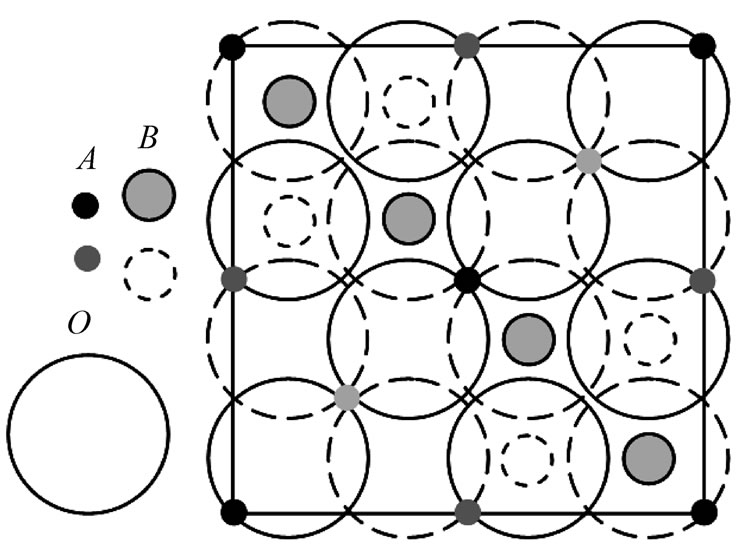
Figure 1. The normal spinel structure of Cobalt Ferrite CoFe2O4 (CoO∙Fe2O3) with a stoichiometry denoted by AB2O4. Only the lower half of the unit cell is shown for projection on (001)
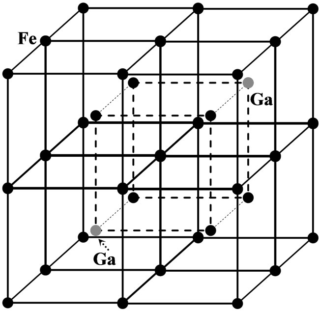
Figure 2. The bcc-structure of the Fe-17Ga alloy (α-Fe)
Terfenol-D can be used in magnetic transducers. It is wellknown that magnetic transducers are increasingly considered as actuators and sensors for numerous aerospace, aeronautic, automotive, industrial, and biomedical applications, for example see [32-34]. Recent progress in studying the cubic structure piezomagnetic crystals Galfenol and Terfenol-D of class m3m for utilization in transducers and sensors can be additionally found in [35-38]. Section 2 theoretically describes SAW propagation in piezomagnetic cubic crystals.
2. Theory
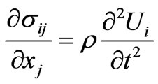
The rectangular coordinate system (x1, x2, x3) is shown in figure 3. The suitable crystal cut and propagation direction was obtained by 450-rotation around the x2-axis directed along the lowest odd-order symmetry axis of a piezomagnetic cubic crystal. Therefore, the piezomagnetic waves with the anti-plane polarization propagate along the crystal surface in direction [101]. It is noted that the x2-axis is perpendicular to the sagittal plane. Theoretical description of wave propagation in cubic piezomagnetics is similar to that for cubic piezoelectrics, for example see [27,39,40]. The constitutive equations for a piezomagnetic material can be expressed in terms of the strains τ and the magnetic field H. Strains are related to mechanical displacements: τij = (∂Ui/∂xj + ∂Uj/∂xi)/2 [41]. The governing mechanical equilibrium is ∂σij/∂xj = 0 and the governing magnetostatic equilibrium is ∂Bi/∂xi = 0 where σij and Bi are the stress tensor and magnetic flux, respectively. A piezomagnetic medium possesses the elastic Cijkl and piezomagnetic hijk coefficients as well as the magnetic permeability coefficients μij and the medium density r.
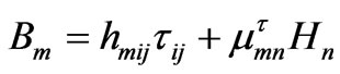
It is necessary to write governing equations for the linear case. Constitutive relations are written as follows:
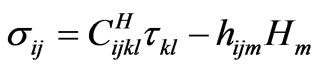 (1)
(1)
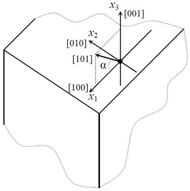
Figure 3. The rectangular coordinate system for a piezomagnetic cubic monocrystal, α = 45o
 (2)
(2)
in which σij and τij are the stress and strain tensors, respectively; Bm and Hm are components of the magnetic induction (i.e. magnetic flux) and magnetic field: Hm = – ∂ψ/∂xm, where ψ is the magnetic potential. The indices i, j, k, l, m, and n run from 1 to 3. According to Voigt’s usual notation, Cijkl, hijm, and μmn can be written as 6 × 6, 3 × 6, and 3 × 3 matrices standing for the elastic, piezomagnetic, and magnetic tensors, respectively. They are thermodynamically defined as follows:
 (3)
(3)
 (4)
(4)
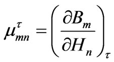 (5)
(5)
where the elastic constants Cijkl are defined at constant magnetic field and the magnetic constants μmn are defined at constant strain.
In the quasi-static approximation, the equations of motion of an elastic medium and magnetostatics are
 and
and 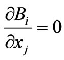 (6)
(6)
In Equation (6), Ui denote the mechanical displacement components; t is time. Using Equations (1), (2), (6) and ψ = U4, one can write the coupled equations of motion for a piezomagnetic medium in the following form:
 (7)
(7)
Solutions of homogeneous partial differential Equations (7) of the second order are found in the following plane wave form:  and
and 
 where the index i runs from 1 to 3. Ui0 and ψ are initial amplitudes; j = (–1)1/2. ksr denotes the scalar multiplication of two vectors and ω is the angular frequency. {k1, k2, k3} = k{n1, n2, n3} are the components of the wavevector ks, {x1, x2, x3} are the components of the real space vector r, and {n1, n2, n3} are the directional cosines.
The coupled equations of motion can be readily written in the following simplified form, leaving only equations for waves with polarization perpendicular to the sagittal plane as well as non-zero components of the material tensors for the studied direction [101] of wave propagation:
 (8)
(8)
In Equation (8), the mechanical displacement component U2 is directed along the x2-axis, see figure 3:
 (9)
(9)
where the phase velocity is defined as vph = w/k (k is the wavenumber in direction of wave propagation). For piezomagnetic cubic crystals, it is possible to write C44 = C66 = C and μ11 = μ33 = μ. It is noted that many propagation directions perpendicular to direction [010] can exist. It is also possible to cut a cubic crystal in order to study wave propagation in direction [101] with h14 = h36 = 0 and the non-zero piezomagnetic constants {–h16, h34} that is shown in Equation (8). The dependence of the normalized piezomagnetic constants on the cubic crystal cuts and propagation directions is shown in figure 4.
Substituting the mechanical displacement U2 and magnetic potential ψ = U4 of Equation (9) into Equation (8), the equations of motion can readily be written in the wellknown tensor form, using corresponding GL-components in the Green-Christoffel equation, (GLrw – δrwρVph) Ur = 0
[39,41]: ,
,  and
and  with n3 = k3/k. In the GL-equation, r and w run from 1 to 4, δrw is the Kronecker delta for r < 4 and w < 4, δ44 = 0, Ur = {U1, U2, U3, ψ}. Therefore, the following system of two homogeneous equations for pure SH-waves can be written as:
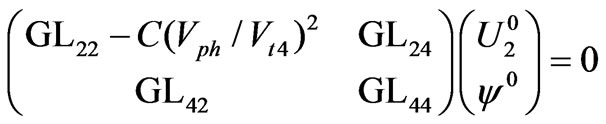 (10)
(10)
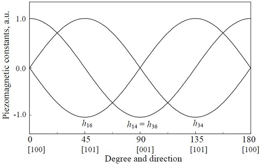
Figure 4. The dependence of the normalized piezomagnetic constants h14 = h36, h16, and h34 on the propagation directions with the Euler angles {0o, θ, 0o} for piezomagnetic cubic crystals, where there is rotation around the x2-axis
In Equation (10), the directional cosines are defined as follows: n1 ≡ 1, n2 ≡ 0 and n3 = n3. The velocity Vt4 is also defined as follows: Vt4 = (C44/ρ)1/2. Setting the matrix determinant equal to zero in Equation (10), the suitable phase velocity Vph satisfying boundary conditions discussed in the following section and four polynomial roots n3(p)(Vph), as well as the functions U20(Vph) and φ0(Vph), can then be found. For example, the functions can be taken in the following form:  and
and . It is noted that for the piezomagnetic surface Bleustein-Gulyaev waves, the GL24 and GL42 components are as follows:
 .
.
Substituting m = 1 + n32 and expanding the matrix determinant in Equation (10), the following polynomial can be obtained from Equation (10):
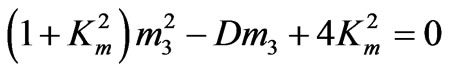 with
with 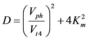 (11)
(11)
of which two roots can be found as follows
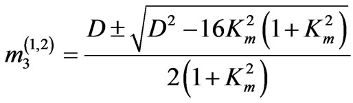 (12)
(12)
giving four polynomial roots of Equation (10)
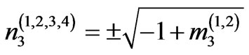 (13)
(13)
The polynomial roots n3(1,2,3,4) actually represent the eigenvalues. For each eigenvalue n3(n), the corresponding eigenvector can be found in the following form: (U2(n), ψ(n)) where the index n runs from 1 to 4. The coefficient Km2 in Equations (11) and (12) is the static coefficient of the magnetomechanical coupling (CMMC):
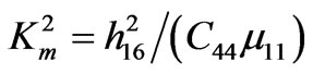 (14)
(14)
It is also noted that the speed Vtm of the bulk SH-wave is given by the following Formula:
 (15)
(15)
Analyzing the roots for propagation direction [101] in Equations (12) and (13), it can be found that all complex roots will be calculated when the expression under the square root in Equation (12) is negative. That fulfills for velocities Vph being lower than some velocity VKm obtained solving the following Equation from (12):
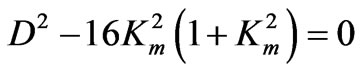 (16)
(16)
and defined by the following formula:
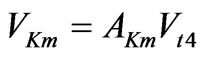 with
with 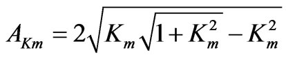 (17)
(17)
It is clearly seen in Equation (17) that the factor AKm shown in figure 5 is a function of the CMMC Km2. The other function f (Km2) = (1 + Km2)1/2 = Vtm/Vt4 from Equation (15) is also shown in figure 5. The function Akm (Km2 = K02 = 1/3) approaches the function f (Km2) = (1 + Km2)1/2 giving the following equality: VKm = Vtm (see figure 5). It is noted that only complex polynomial roots can exist when Vph < VKm. The CMMC K02 = 1/3 is readily found by substituting the velocity Vtm from Equation (15) instead of the phase velocity Vph in Equation (16). Note that when Km2 < K02 there are all imaginary roots for Vph > VKm, but a big Km2 > K02 gives real roots when Vph > VKm. It is also noted that only complex or imaginary roots with negative imaginary parts are chosen in order to cope with wave damping towards the depth of a crystal corresponding to negative values of the x3-axis shown in figure 3.
Table 1 lists experimental data for Galfenol (83% of Fe and 17% of Ga) obtained in [42,43]. It is clearly seen that the static CMMC Km2 for cubic Galfenol can be as high as~0.42 that is larger than 1/3, see also table 2. The Galfenol density ρ was taken from [31], which can depend on material synthesis. For example, [31] gives a Galfenol density of ~5900 kg/m3 for a typical sintered disk that is only 74% of maximum possible density. It is noted that the material density of Fe is ~7848 kg/m3 (see [44]). According to [31,42] as well as many Galfenol Workshops at the University of Maryland, the shear elastic constant c44 = c for Galfenol relatively slightly depends on both temperature and concentration of ga in fe. The elastic constant c can have values from ~120 GPa to ~135 gPa. According to [31], the static CMMC Km2 for cubic Terfenol-D can be usually about two times larger than that for Galfenol under the same conditions. However, it is interesting to compare some characteristics of Galfenol and Terfenol-D. Therefore, Terfenol-D with a very big Km2 ~1.2 was chosen from [45] for numerical calculations suggesting that Terfenol-d has the cubic symmetry. The piezomagnetics CoFe2O4 [16,46] is also listed in table 2 for comparison, suggesting the cubic symmetry for the crystal.
Since the experimental data listed in Table 1 is given for different experimental conditions, it is possible to calculate the single piezomagnetic constant h = h14 for cubic Galfenol, using known values of Km and C, as well as the measured values of magnetic permeability μ given in table 1. The strain τ and magnetic flux B can be also written based on the following linear constitutive piezomagnetic equations:

Figure 5. The dependence of both the factor AKm and the function (1 + Km2)1/2 on the values of Km2 from 0 up to 3. The insertion shows the AKm(Km2) for small values of the Km2

Table 1. The material characteristics following [42,43] for Galfenol Fe0.83Ga0.17 (m3m); EB = 7.7 × 10¹⁰ [N/m2]. The magnetic permeability coefficient of a vacuum is μ0 = 4π × 10–7 [H/m]~12.566371 × 10–7 [(V × s)/(A × m)]. The static coefficient of magnetomechanical coupling (CMMC) Km in the last column was also announced in [42,43]
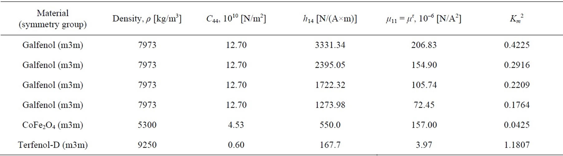
Table 2. The elastic C44 and piezomagnetic h14 constants as well as the material density ρ and magnetic permeability coefficient μ11 for the piezomagnetic cubic crystals: Galfenol [42,43], CoFe2O4 [16,46], and Terfenol-D [45]. The coefficient of magnetomechanical coupling (CMMC) Km2 in the last column can be calculated with Formula (14)
 (18)
(18)
 (19)
(19)
where sH is the compliance at constant magnetic field H and μσ is the magnetic permeability at a constant stress σ. Note that Equation (19) incorporates the direct magnetostrictive effect in which magnetic flux is generated by stresses in the piezomagnetic material. The piezomagnetic constants q and q* are thermodynamically defined as follows, assuming q = q*:
 and
and  (20)
(20)
The piezomagnetic coefficient q symbolizes the axial magnetostriction coefficient and represents the change in strain per change in magnetic field at a constant stress. The parameter q* represents the change in magnetic induction per change in stress at a constant magnetic field.
The short circuit elastic modulus EB represents the stiffest-material condition, which occurs when all available magnetic energy has been transduced into elastic potential energy. When energy is transferred from the elastic to the magnetic regime the effective modulus decreases to the value of EH. It has been shown by invoking linear transduction considerations that these two elastic moduli are related by the magnetomechanical coupling coefficient Km2 (0 ≤ Km2 ≤ 1) as follows [47]:
 (21)
(21)
In a similar manner, the intrinsic or uncoupled magnetic permeability μσ of Equation (19) can be reduced to a value corresponding to the constant strain permeability με because of the energy conversion from the magnetic to the elastic regime. The permeabilities are related by:
 (22)
(22)
It is emphasized that expressions (21) and (22) are only valid for linear systems and significant corrections are necessary in order to extend these formulae to the full nonlinear regime. However, they are highly useful to illustrate the exchange mechanisms taking place in magnetostrictive transduction.
The static CMMC Km2 can be also written as follows:
 (23)
(23)
Therefore, the single non-zero piezomagnetic constant h can be calculated with the following formula, using Equations (14), (22), and (23):
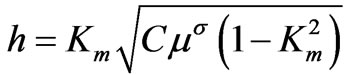 (24)
(24)
Table 2 lists the piezomagnetic constant h for cubic Galfenol corresponding to the experimentally measured values of the magnetic permeability μσ at constant stress σ.
For the free space, Laplace’s equation of type Dψ = 0 is written in the following form: (k12 + k32) ψ0 = 0 where μ0 is the magnetic constant for the free space. The magnetic potential for the free space can be written as follows: ψ0 = F(0)exp (– k1x3) exp [j (k1x1 – wt)]. The potential ψ0 must decrease according to any increase in the coordinate x3 (see figure 3). It is now possible to use the material constants in mechanical and magnetic boundary conditions.
3. Boundary Conditions for Surface SH-waves
The mechanical boundary conditions of a magnetoelastic material which occupies the half-space x3 < 0 must be satisfied together with the magnetic conditions of a magnetically closed (B3 = 0) or magnetically open (ψ = 0) surface. The realization of each of these boundary conditions is described in [17]. There is the single mechanical boundary condition for the normal component of the stress tensor: σ32 = 0 at x3 = 0, where,
 (25)
(25)
Also, there are the magnetic boundary conditions: continuity of the normal component B3 of the magnetic flux at x3 = 0 being the interface between a vacuum (B3f) and the crystal surface (B3 = B3f) where,
 (26)
(26)
and continuity of the magnetic potential U4 = ψ at x3 = 0 (ψ = ψ f) where
 and
and  (27)
(27)
Therefore, using Equations (25)-(27), two homogeneous equations for the case of a magnetically closed surface can be readily written as follows:
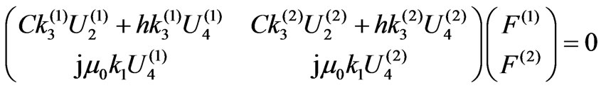 (28)
(28)
For a magnetically open surface, the following homogeneous equations can also be written in the corresponding form:
 (29)
(29)
Therefore, the corresponding boundary-condition determinants (BCDs) of matrices in Equations (28) and (29) for both cases represent complex numbers.
The complete mechanical displacement U2Σ and magnetic potential ψΣ = U4Σ can be written in the plane wave form as follows:
 (30)
(30)
The corresponding weight functions F(1) and F(2) are found from Equations (28) and (29), which can give the same eigenvectors (U20(1), ψ0(1)) and (U20(2), ψ0(2)) for two equal eigenvalues n3(1) = n3(2), and hence . It is obvious that for this case the weight factors
 will zero the complete mechanical displacement U2Σ and magnetic potential ψΣ in Equations (28) and (29) giving “latent” characteristics in Equation (30). On the other hand, unequal eigenvalues n3(1) and n3(2) give different eigenvectors (U20(1), ψ0(1)) and (U20(2), ψ0(2)). It is thought that the Vph-solutions with the “latent” characteristics must be experimentally verified due to the fact that some elements of crystals symmetry (screw axis or glide reflection) can be broken near the surface. The same relates to simple reflections and axis if the surface restricts the crystal in such a way that it breaks some simple elements of the crystal class group. It is also noted that Vph- solutions cannot be found when the surface BleusteinGulyaev waves are studied that is an additional difference for finding the BG-waves and USZW-waves.
4. Results and Discussions
Acoustic wave propagation along the surface of piezoelectric material in direction [101] as an instability problem can sustain the surface SH-waves in cubic piezoelectrics that was recently discovered in [27]. Concerning piezomagnetics, it is thought that piezomagnetic SH-SAW can also propagate in direction [101] in cubic piezomagnetics, for instance, crystals of class m3m. Indeed, all cubic crystals of the class possess no piezoelectricity according to [48,49]. Note that concerning transversely-isotropic materials, solutions for the surface BG-waves in piezomagnetics can be written in an identical manner to the wave solutions in piezoelectrics [50]. It is also noted that the velocity VBGmo of piezomagnetic surface BG-wave propagating along the magnetically open surface of transversely-isotropic piezomagnetics (treating the simplest case) can be found with the following well-known formula:
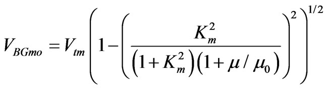 (31)
(31)
The velocity VBGmc of piezomagnetic BG-wave with the magnetically closed surface can be calculated with the following formula:
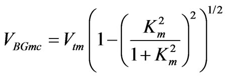 (32)
(32)
Note that Formula (31) for the velocity VBGmo is not applicable for the case of cubic piezomagnetics. For example, formula (31) gives VBGmo~4760.093893 m/s for Galfenol with the largest value of Km2 > 1/3 in the first row in table 3. This value of VBGmo is close to that of Vtm, but not to the value of VKm (see table 3) representing the right result for cubic piezomagnetics with Km2 > 1/3. The same there is for Terfenol-D with Km2~1 in table 2, for which the incorrect velocity calculated with Formula (31) is VBGmo~1179.199962 m/s.
For cubic piezomagnetics with Km2 < 1/3, Formula (31) also gives values of VBGmo being closer to corresponding values of Vtm than true values of VUSZW,o. For example, the velocity VUSZW,o for Galfenol in the fourth row in table 3 with the smallest value of Km2 < 1/3 (see also table 2) is VUSZW,o~4328.763803 m/s. However, Formula (31)

Table 3. The velocities vKm, Vt4, and Vtm (all in m/s) as well as the velocities VUSZW,o and VUSZW,c of the ultrasonic surface Zakharenko waves for [101] propagation direction in the piezomagnetic cubic crystals. The last column gives values of the K2 calculated with Formula (33). All the Galfenols correspond to those listed in tables 1 and 2
gives VBGmo ~4328.783915 m/s that is closer to Vtm~ 4328.798060 m/s. Therefore, the differences ΔBG = VBGmo – Vtm and ΔUSZW = VUSZW,o – Vtm are ~0.014 m/s and ~0.034 m/s, respectively. For comparison, for the piezomagnetic CoFe2O4 with the smallest value of Km2 ~4% from table 2, the true velocity VUSZW,o in table 3 is already very close to the velocity VBGmo ~2985.08072 m/s, which is also very close to the velocity Vtm. Note that the relative magnetic permeability μ/μ0 in Formula (31) for piezomagnetics is about one order larger than the corresponding relative dielectric constant ε/ε0 for piezoelectrics for the same Km2 = Ke2, where Ke2 is the static coefficient of electromechanical coupling (CEMC), and ε and ε0 are the single electric constants for a piezoelectrics and free space, respectively. That can result in mm/s-difference for piezomagnetics compared with cm/s-difference for piezoelectrics between the corresponding BG-wave velocity and bulk wave velocity Vt. That can result in significantly larger penetration depth of surface BG and USZW-waves for piezomagnetics towards negative values of the x3-axis in figure 3. It is also noted that the velocity VBGmc for a magnetically closed surface can be readily calculated with Formula (32), with which the velocity of interfacial Maerfeld-Tournois waves [12] is also calculated. The interfacial Maerfeld-Tournois waves can propagate along the interface of two transverselyisotropic half-spaces of class 6 mm. Concerning cubic piezomagnetics, it is expected that some interfacial waves can also propagate that can be further researched.
Using the velocities VUSZW,o and VUSZW,c for the USZWwaves, it is possible to evaluate the coefficient of magnetomechanical coupling (CMMC) K2 for the piezomagnetic cubic crystals listed in table 3. Indeed, it is thought that it is possible to use the well-known formula that is used for piezoelectrics. Therefore, the coefficient K2 can be evaluated with the following formula:
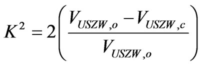 (33)
(33)
For Galfenol in tables 2 and 3, the evaluated value of K2 is as high as 2.26% for the smallest value of Km2. The value of K2 increases with increase in Km2 to the biggest value of 8.25%. This value of 8.25% for the piezomagnetic Galfenol in the first row of table 3 can be compared with that for Terfenol-D in the Table: K2(Terfenol-D)~ 9.13%. It is clearly seen in the second and third tables that a big value of Km2~1.2 for Terfenol-D being about three times larger than the biggest value of Km2 for Galfenol does not give a significant rise in the coefficient K2. The rise is smaller than 1%. That can be explained using the following fact: the velocity VUSZW,o for cubic piezomagnetics with a giant coefficient Km2 is situated slightly below the speed VKm, but not slightly below the speed Vtm (see also figure 5). That results in lower coefficient K2. Therefore, it can be concluded that the coefficient K2 for cubic piezomagnetics with a giant Km2 is about 8% to 9% and cannot be larger than 10%. It is thought that the coefficient K2 for the surface BG-waves in transversely-isotropic piezomagnetics with a giant Km2 can be larger than 10%, according to Formulae (31)–(33) and figure 5. The sample behaviors of the boundarycondition determinant (BCD3) around the phase velocity solutions for the piezomagnetic monocrystals CoFe2O4 and Galfenol are shown in figures 6 and 7, respectively. Figure 8 shows the dependence of the Vph on the coefficient Km for the Fe-17Ga alloy. Note that any change in the material density will change both the velocities Vt4 and Vtm (Vt4), but not the coefficients Km2 and K2.
5. Conclusions
This paper addresses the theoretical investigations of piezomagnetic acoustic waves propagating along the surface of cubic crystals. The ultrasonic surface Zakharenko waves (USZWs) can propagate in cubic piezomagnetics when direction [101] is parallel to the crystal surface. The computer simulation was done for the widelycalled piezomagnetic crystals Galfenol, Terfenol-D, and
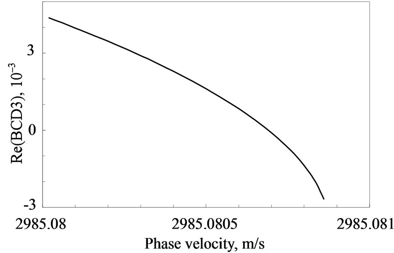
Figure 6. The behavior of the boundary-condition determinant (BCD3) for the piezomagnetic monocrystal CoFe2O4

Figure 7. The behavior of the boundary-condition determinant (BCD3) for the piezomagnetic bcc-cubic monocrystal of the Fe-17Ga alloy for Km = 0.65

Figure 8. The dependence of the phase velocity Vph on the coefficient Km for the Fe-17Ga alloy, where the functions VUSZW,o(km) and VUSZW,c(km) are shown by solid and dashed lines, respectively
CoFe2O4 suggesting the cubic symmetry. The cubic piezomagnetics Galfenol and Terfenol-D can possess large values of Km2, where Km2 is the static coefficient of magnetomechanical coupling. The simulations have shown that for a cubic crystal with a large Km2 > 1/3 (even Km2 > 1 for Terfenol-D) the coefficient K2 is as big as 8%-9% and not larger than 10%. It is noted that a big Km2 > 1 does not give a significant rise to the coefficient K2 for the case of Km2~1/3. That is due to the fact that velocity solutions for large values of Km2 > 1/3 are found just below the velocity VKm, but not just below the velocity Vtm. This theoretical study of cubic piezomagnetics allows use of suitable surfaces of piezomagnetic cubic crystals in non-destructive testing and evaluation that was also recently done for cubic piezoelectrics.
6. Acknowledgements
The author is grateful to all the Referees for their constructive comments.
REFERENCES
- J. V. Suchtelen, “Product Properties: A New Application of Composite Materials,” Philips Research Reports, Vol. 27, No. 1, 1972, pp. 28-37.
- J. V. D. Boomgaard, D. R. Terrell, R. A .J. Born and H. F. J. I. Giller, “An in Situ Grown Eutectic Magnetoelectric Composite-Material: 1. Composition and Unidirectional Solidification,” Journal of Materials Science, Vol. 9, No. 10, 1974, pp. 1705-1709.
- A. M. J. G. V. Run, D. R. Terrell and J. H. Scholing, “An in Situ Grown Eutectic Magnetoelectric Composite-Material: 2. Physical Properties,” Journal of Materials Science, Vol. 9, No. 10, 1974, pp. 1710-1714.
- J. V. D. Boomgaard, A. M. J. G. V. Run and J. V. Suchtelen, “Piezoelectric-Piezomagnetic Composites with Magnetoelectric Effect,” Ferroelectrics, Vol. 14, 1976, pp. 727-728.
- V. E. Wood and A. E. Austin, “Magnetoelectric Interaction Phenomena in Crystals,” In A. J. Freeman, H. Schmid, Eds., Gordon and Breach Science Publishers, Newark, New York, 1975, pp. 181-194.
- Y. N. Venevtsev, V. V. Gagulin and I. D. Zhitomirsky, “Material Science Aspects of Seignette-Magnetism Problem,” Ferroelectrics, Vol. 73, 1987, pp. 221-248.
- M. Fiebig, “Revival of the Magnetoelectric Effect,” Journal of Physics D: Applied Physics, Vol. 38, No. 8, 2005, pp. 123-152.
- P. Curie, “Sur la Symétrie des Phénomènes Physiques: Symétrie d'un Champ électrique et d'un Champ Magnétique,” Journal de Physique, 3e Série, Vol. 3, 1894, pp. 393-415.
- L. Rayleigh, “On Waves Propagated along the Plane Surface of Elastic Solids,” Proceedings of the London Mathematical Society, Oxford, Vol. 17, 1885, pp. 4-11.
- J. L. Bleustein, “A New Surface Wave in Piezoelectric Materials,” Applied Physics Letters, Vol. 13, No. 12, 1986, pp. 412-413.
- Y. V. Gulyaev, “Electroacoustic Surface Waves in Solids,” Soviet Physics Journal of Experimental and Theoretical Physics Letters, Vol. 9, 1969, pp. 37-38.
- C. Maerfeld and P. Tournois, “Pure Shear Elastic Surface Wave Guide by the Interface of two Semi-Infinite Media,” Applied Physics Letters, Vol. 19, No. 4, 1971, pp. 117-118.
- E. Danicki, “New Interfacial Shear Wave in Piezoelectrics,” Applied Physics Letters, Vol. 64, No. 8, 1994, pp. 969-970.
- A. E. H. Love, “Some Problems of Geodynamics,” Cambridge University Press, London, 1911.
- C. W. Nan, “Magnetoelectric Effect in Composites of Piezoelectric and Piezomagnetic Phases,” Physical Review B, Vol. 50, No. 9, 1994, pp. 6082-6088.
- S. Srinivas, J. Y. Li, Y. C. Zhou and A. K. Soh, “The Effective Magnetoelectroelastic Moduli of Matrix-Based Multiferroic Composites,” Journal of Applied Physics, Vol. 99, No. 4, 2006, pp. (043905)1-7.
- V. I. Al’shits and A. N. Darinskii and J. Lothe, “On the Existence of Surface Waves in Half-Infinite Anisotropic Elastic Media with Piezoelectric and Piezomagnetic Properties,” Wave Motion, Vol. 16, No. 3, 1992, pp. 265- 283.
- A.-K. Soh and J.-X. Liu, “Interfacial Shear Horizontal Waves in a Piezoelectric-Piezomagnetic Bi-Material,” Philosophical Magazine Letters, Vol. 86, No. 1, 2006, pp. 31-35.
- K.-Q. Hu and G.-Q. Li, “Constant Moving Crack in a Magnetoelectroelastic Material under Anti-Plane Shear Loading,” International Journal of Solids and Structures, Vol. 42, No. 9-10, 2005, pp. 2823-2835.
- X.-F. Li, “Dynamic Analysis of a Cracked MagnetoelectrOelastic Medium under Anti-Plane Mechanical and InPlane Electric and Magnetic Impacts,” International Journal of Solids and Structures, Vol. 42, No. 11-12, 2005, pp. 3185-3205.
- J. Chen, E. Pan and H. Chen, “Wave Propagation in Magneto-Electro-Elastic Multilayered Plates,” International Journal of Solids and Structures, Vol. 44, No. 3-4, 2007, pp. 1073-1085.
- K. Mori and M. Wuttig, “Magnetoelectric Coupling in Terfenol-D/polyvinylidenedifluoride Composites,” Applied Physics Letters, Vol. 81, No. 1, 2002, pp. 100-101.
- M. I. Bichurin, D. A. Filippov, V. M. Petrov, V. M. Laletsin, N. Paddubnaya and G. Srinivasan, “Resonance Magnetoelectric Effects in Layered Magnetostritive-Piezoelectric Composites,” Physical Review B, Vol. 68, No. 13, 2003, pp. (132408)1-4.
- K. Srinivas, G. Prasad, T. Bhimasankaram and S. V. Suryanarayana, “Electromechanical Coefficients of Magnetoelectric PZT-CoFe2O4 Composite,” Modern Physics Letters B, Vol. 14, No. 17-18, 2000, pp. 663-674.
- P. Yang, K. Zhao, Y. Yin, J.G. Wan and J.S. Zhu, “Magnetoelectric Effect in Magnetostrictive/Piezoelectric Laminate Composite Terfenol-D/LiNbO3 [(zxtw)-129°/ 30°],” Applied Physics Letters, Vol. 88, No. 17, 2006, pp. (172903)1-3.
- Y. V. Gulyaev and F. S. Hickernell, “Acoustoelectronics: History, Present State and New Ideas for a New Era,” Acoustical Physics, Vol. 51, No. 1, 2005, pp. 81-88.
- A. A. Zakharenko, “New Solutions of Shear Waves in Piezoelectric Cubic Crystals,” Journal of Zhejiang University SCIENCE, Vol. 8, No. 4, 2007, pp. 669-674.
- W. Kleber, “An Introduction to Crystallography,” VEB Verlag Technik, Berlin, 1970.
- M. J. Dapino, “Nonlinear and Hysteretic MagnetomechaNical Model for Magnetostrictive Transducers,” PhD Thesis, Iowa State University, 1999.
- A. E. Clark, J. B. Restorff, M. Wun-Fogle, T. A. Lograsso and D. L. Schlagel, “Magnetostrictive Properties of Bodycentered Cubic Fe-Ga and Fe-Ga-Al Alloys,” IEEE Transactions on Magnetics, Vol. 36, No. 5, 2000, pp. 3238- 3240.
- R. A. Kellog, “Development and Modeling of Iron-Gallium Alloys,” PhD Thesis, Iowa State University, 2003.
- M. J. Dapino, “On Magnetostrictive Materials and their Use in Adaptive Structures,” International Journal of Structural Engineering and Mechanics, Vol. 17, No. 3-4, 2004, pp. 303-329.
- M. J. Dapino, F. T. Calkins and A. B. Flatau, “Magnetostrictive Devices,” Wiley Encyclopedia of Electrical and Electronics Engineering, In. J. G. Webster, Ed., John Wiley and Sons Inc., New York, Vol. 12, 1999, pp. 278- 305.
- J. B. Restorff, “Magnetostrictive Materials and Devices,” Encyclopedia of Applied Physics, Vol. 9, 1994, pp. 229- 244.
- R. Chung, R. Weber and D. Jiles, “A Terfenol-D Based Magnetostrictive Diode Laser Magnetometer,” IEEE Transactions on Magnetics, Vol. 27, No. 6, 1991, pp. 5358- 5243.
- M. J. Dapino, R. C. Smith and A. B. Flatau, “StructuralMagnetic Strain Model for Magnetostrictive Transducers,” IEEE Transactions on Magnetics, Vol. 36, No. 3, 2000, pp. 545-556.
- P. R. Downey and A. B. Flatau, “Magnetoelastic Bending of Galfenol for Sensor Applications,” Journal of Applied Physics, Vol. 97, No. 10, 2005, pp. (10R505)1-3.
- J. Atulasimha, A. B. Flatau and R. A. Kellogg, “Sensing Behavior of Varied Stoichiometry Single Crystal Fe-Ga,” Journal of Intelligent Material Systems and Structures, Vol. 17, No. 2, 2006, pp. 97-105.
- G. W. Farnell and E. L. Adler, “Elastic Wave Propagation in Thin Layers,” Physical Acoustics: Principles and Methods, In. W. P. Mason and R. N. Thurston Eds., Academic Press, New York, Vol. 9, 1972, pp. 35-127.
- C. Lardat, C. Maerfeld and P. Tournois, “Theory and Performance of Acoustical Dispersive Surface Wave Delay Lines,” Proceedings of the IEEE, Vol. 59, No. 3, 1971, pp. 355-368.
- V. E. Lyamov, “Polarization Effects and Interaction Anisotropy of Acoustic Waves in Crystals,” MSU Publishing, Moscow, 1983.
- A. E. Clark, K. B. Hathaway, M. Wun-Fogle, J. B. Restorff, T. A. Lograsso, V. M. Keppens, G. Petculescu and R. A. Taylor, “Extraordinary Magnetoelasticity and Lattice Softening in Bcc Fe-Ga Alloys,” Journal of Applied Physics, Vol. 93, No. 10, 2003, pp. 8621-8623.
- A. E. Clark, “Structural Fe-based Alloys with High Magnetostriction,” Galfenol Workshop, University of Maryland, 29 January 2004.
- A. A. Zakharenko, “On Cubic Crystal Anisotropy for Waves with Rayleigh-Wave Polarization,” Non-Destructive Testing and Evaluation, Vol. 21, No. 2, 2006, pp. 61-77.
- T. J. C. Liu and C. H. Chue, “On the Singularities in a Bimaterial Magneto-Electro-Elastic Composite Wedge under Anti-Plane Deformation,” Composite Structures, Vol. 72, No. 2, 2006, pp. 254-265.
- F. Ramirez, P. R. Heyliger and E. Pan, “Free Vibration Response of Two-Dimensional Magneto-Electro-Elastic Laminated Plates,” Journal of Sound and Vibration, Vol. 292, No. 3-5, 2006, pp. 626-644.
- A. E. Clark, “Magnetostrictive Rare Earth-Fe2 Compounds,” Ferromagnetic Materials, In. E. P. Wohlfarth, Ed., North-Holland Publishing Company, Amsterdam, Vol. 1, Chapter 7, 1980, pp. 531-589.
- V. I. Al’shits and V. N. Lyubimov, “On Existence of Piezoelectric and Piezomagnetic Properties of Anisotropic Media,” Soviet Kristallographia, Moscow, Vol. 35, No. 2, 1990, pp. 483-484.
- D. Royer and E. Dieulesaint, “Elastic Waves in Solids I,” Springer-Verlag, New York, 2000.
- Y. V. Gulyaev, I. E. Dikshtein and V. G. Shavrov, “Magnetoacoustic Surface Waves in Magnetic Crystals at Reorientation Phase Transitions,” Uspekhi Phizicheskikh Nauk, Moscow, Vol. 167, No. 7, 1997, pp. 735-750.