Int'l J. of Communications, Network and System Sciences
Vol. 5 No. 6 (2012) , Article ID: 19653 , 8 pages DOI:10.4236/ijcns.2012.56041
Scheduler Algorithm for Multi-Class Switch with Priority Threshold
1Telekom Research & Development, Selangor, Malaysia
2Faculty of Science & Technology, Universiti Sains Islam Malaysia (USIM), Negeri Sembilan, Malaysia
3Faculty of Computer Science & IT, Universiti Putra Malaysia (UPM), Selangor, Malaysia
Email: {abd_aziz, drkamsani}@tmrnd.com.my, {drkzaman, kamarudin}@usim.edu.my, azreen@fsktm.upm.edu.my
Received March 29, 2012; revised April 23, 2012; accepted May 11, 2012
Keywords: Scheduler; Priority Thresholds; Multi-Class; Quality of Service (QoS)
ABSTRACT
The requirement for guaranteed Quality of Service (QoS) have become very essential since there are numerous network base application is available such as video conferencing, data streaming, data transfer and many more. This has led to the multi-class switch architecture to cater for the needs for different QoS requirements. The introduction of threshold in multi-class switch to solve the starvation problems in loss sensitive class has increased the mean delay for delay sensitive class. In this research, a new scheduling architecture is introduced to improve mean delay in delay sensitive class when the threshold is active. The proposed architecture has been simulated under uniform and non-uniform traffic to show performance of the switch in terms of mean delay. The results show that the proposed architecture has achieved better performance as compared to Weighted Fair Queueing (WFQ) and Priority Queue (PQ).
1. Introduction
In the current communication network, the desire of having multiple applications on a single traffic stream has become essentials. The multi-class traffic [1-9] is used to classify these applications based on its QoS requirements. The use of priority provides the means to give different classes of service a different type of traffic [4]. This needs an efficient scheduling algorithm to handle the flows of multi-class traffic packets.
Scheduling algorithm plays an important role in obtaining a high performance in multi-class switch. Priority scheduling technique is commonly used in multi-class switch. This technique is used to classify the priority level for each class. Unfortunately, most of the existing scheduling algorithm [1,2,4-6] only strives to maximize the QoS level in delay sensitive class for each arrival cell without considering the performance in lost sensitive class, which may result in poor QoS for this class, especially when the system is in heavy load. Scheduling algorithm for a single priority class may not perform well when it is applied to a multi-class scheduling [6]. The introduction of Weighted Fair Queue (WFQ) has improved the performance of the multi-class switch.
In Weighted Fair Queue (WFQ), traffic classes are served based on the fixed weight assigned to the related queue [7,8]. The weight is determined according to the QoS parameters, such as service rate or delay. This technique is not suitable under high-traffic load because of the fixed weight that is assigned to the queue and introduces starvation problems to loss sensitive class. The introduction of adaptive technique in threshold levels selection [9] has improved the performance. The priority given in these switch will determine the cells from which class should be served first with consideration of QoS requirements.
Despite improving the performance of loss sensitive class, designing a high speed packet multi-class switching with the threshold will introduce problems such as the drop of QoS performance for delay sensitive class whenever the threshold is active. This research is expected to improve the mean delay in delay sensitive class when the threshold for loss sensitive class is active.
In order to achieve the stated objective, the new scheduling algorithm is introduced to improve the delay sensitive class performance. Non-blocking switch such as the crossbar switch is used as a switching fabric. The scheduler wills evaluate all possible connections between all input port and output port for every class in the switch in order to make the best decision.
In this paper, we proposed an efficient scheduling technique to control the flow of the cells for both loss sensitive class and delay sensitive class in the multi-class switch with the threshold. This scheduler is able to detect and match the idle output port for delay sensitive class even in the present of the active threshold in loss sensitive class within the same input port.
2. Proposed Model
The proposed multi-class switch architecture with N ports serving 2 classes of traffics is shown in Figure 1. Priority switch is used to forward delay sensitive packet (Class 1) faster than loss sensitive packet (Class 0).
The delay requirement for class j cells is defined by Dj where j = 0, 1 and D0 > D1. In other words, the delay requirement for Class 1 is more stringent than Class 0 for system shown in Figure 1. Thus, cells that queue in Class 0 have the lowest priority and cells that queue in Class 1 have the highest priority. These delay requirements are set based on the QoS requirement for different type of applications.
Time slot is used to represent the time of one cell arrival at the input port or cell departure at the output port. The period of time slot Ts, where s = 0, 1, 2, ··· is set to be equal to the time to process a single cell when the server is idle.
The class j cells arrive at the input port in every time slot according to Bernoulli distributions with mean lj. The cell is classified based on its delay requirement. In this architecture, the class of the cell is stored in the header. Arrival cells for Class j (lj) is queued in the FirstIn-First-Out (FIFO) buffer while waiting to be served.
The threshold setting is introduced in order to give some privileges to cells in lower priority class. In the case when there are cells from different classes are waiting at HoL; the scheduler will select the cell with high priority to be served. However, when the threshold is active, the scheduler will select the cell in the low-priority class. The losing cells in the contention must wait in the queue. In case when the threshold is active, and the
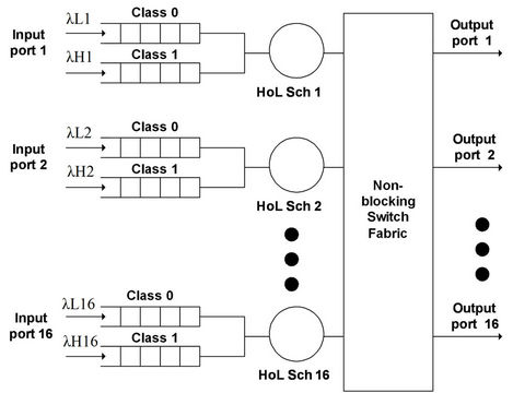
Figure 1. Multi-class switch architecture.
cells from both classes are destined to the different output port that is idle, both cells will be selected if there is no contention.
3. Thresholds in Multi-Class Input Buffer
In multi-class switch, priority is given to delay sensitive packets compare to loss sensitive packets. This means, the cells from real time packets or delay sensitive packets in Class 1 are served first while cells from non-real time packets in Class 0 are queued in the buffer while waiting to be served. This will create a large amount of delay and starvation problem in non-real time class. To overcome this problem, scheduling has to give some priority to cells in Class 0.
To achieve this goal, each individual class will have their own buffer to accommodate different traffic classes. This can eliminate the head-of-line (HoL) for different classes blocking effects.
In normal cases, the scheduling algorithm for multiclass traffic only considers one parameter; priority cell setting or probability of serving low priority classes. In this research, two parameters have been selected to set the threshold level; the number of Class 0 cells in the queue (Nb) and the probability on serving the Class 0 cells (PSC0) over the Class 1 cells. The threshold values are set based on the minimum requirement for high-priority class, arrival rate and buffer size of the switch. Therefore, the threshold settings can be adjusted to optimizing the total cell delay for both classes.
The number of Class 0 cells in the queue (Nb) parameter is chosen because of the limited buffer size available in FPGA. The need to adjust the Nb parameter is necessary to reduce the packet loss due to buffer full. This parameter is adjusted based on size of buffer used to stored cell in Class 0.
Figure 2 illustrates the threshold active signal for setting at Class 0 buffer to two (Nb = 2). The threshold signal is active when the buffer occupancy.
The probability on serving the Class 0 cells (PSC0) parameter is chosen in order to control the variation of delay between real time cell and non-real-time cell based on the real time QoS requirements. This is necessary in order to achieve better performance for Class 0 cells.
All arrivals for Class 0 cells and Class 1 cells are stored
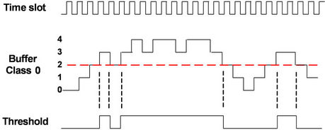
Figure 2. Threshold active signal with setting of Nb = 2.
in the First-In-First-Out (FIFO) buffer while waiting for their turns to be served. Selection from FIFO HoL between Class 0 and class1 is determined by the threshold setting in the scheduler. The scheduler will give priority for Class 0 when there is no cell in class1 or when both thresholds are triggered.
4. Protocol
The scheduler process consists of three phase, i.e. request, grant, departure. Figure 3 shows the protocol of each Head-of-Line (HoL) cell in the input buffer until departure.
All the HoL cells in input buffer will request grant to depart from the input port buffer (i) to output port (j). The granting process will depend on the situation of status either idle output port; availability of priority cells or threshold for low priority class is active. The award of grant to depart will be given by the scheduler. Once the cells received the grant signal, it can be departed from that input port and then update port for new HoL cell.
5. Scheduling Algorithm
The scheduling algorithm is developed to control the cells flows through the switch. Figure 4 shows the bipartite graph for the proposed scheduling algorithm. The high-priority class and low priority class will be control by a centralize scheduler.
A = Matrix of HoL for High priority class (H-HOL);
B = Matrix of HoL for Low priority class (L-HOL);
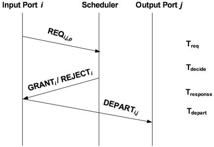
Figure 3. Protocol for scheduler process.
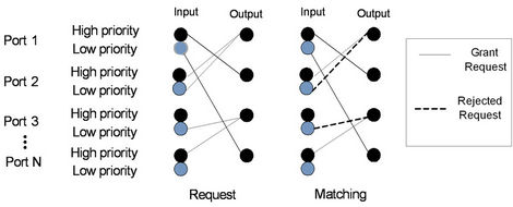
Figure 4. Bipartite graph for the scheduling algorithm.
T = Matrix of threshold of input port of Low priority class;
OT = Vector of output port that have L-HOL cell with threshold;
OA = Vector of output port that have H-HOL cell;
OB = Vector of output port that have L-HOL cell;
γ = Vector of output port of H-HOL that not overlap with L-HOL with threshold;
φ = Vector of output port of L-HOL with and without threshold which not overlap with H-HOL;
H = Matrix of selected H-HOL cell;
L = Matrix of selected L-HOL cell;
1 = [1 1 1 1];
t = [t1 t2 t3 t4].
where ti = {1, 0}
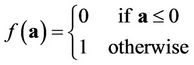 . (1)
. (1)
Vector t is given by the diagonal elements of the matrix T.
 . (2)
. (2)
Vectors oA and oB represent the existing HOL cell for the destined output ports associated with High and Low priority class traffic, respectively. On the other hands, vector oT denotes the location of the output ports that have the active threshold signal. The three vectors are generated using the following expressions:
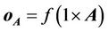 . (3)
. (3)
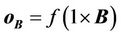 . (4)
. (4)
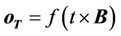 . (5)
. (5)
Note that all vectors’ elements can only assume 1 or 0 value.
The above vectors (oA, oB, and oT) are used to construct diagonal matrices OA, OB, and OT, where the vectors become their respective diagonal elements. These diagonal matrices will be used in our selection section algorithm.
5.1. High Class Traffic Input Selection
Let us define a temporary vector γ to represent the legitimate output arrangement associated with the highclass traffic considering the low-class traffic input with active threshold.
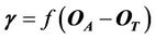 (6)
(6)
Note that, in the event contention, the high class traffic will be blocked. Then we can generate the selected input for the High class traffic, which is represented by a matrix H given by:
 (7)
(7)
However, if more than 1 inputs are possible for the same output, a round robin technique will be used to select the one of these input ports.
5.2. Low Class Traffic Input Selection
Let us define a temporary vector φ given by the following expression:
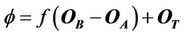 (8)
(8)
Recall that f(a) is given by Equation (8). Hence, f(OB – OA) will eliminate an output port option for the low class traffic if that port has been allocated for the high class traffic. After that, the final φ will also contain legitimate output port information about the low class traffic with active threshold.
Finally, we can define the input selection for the low class traffic by using the following equations:
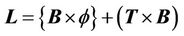 (9)
(9)
The L matrix contains input selection weight for the low-class traffic. Similar to the previous case, whenever exists more than 1 input port with the same maximum weight, a round-robin technique will be used to select the one of these input ports.
The maximum weight in the row index of each column will determine the input ports for each output port. The output port is only able to select one input port either from H or L, the γ matrix has eliminated the overlap input selection for high-priority class traffic and j matrix has eliminated the overlap input selection for low priority class traffic.
6. Hardware Design
The hardware design of the scheduler is developed to evaluate the performance of the multi-class switch. The design of 16 × 16 multi-class switch scheduler can be divided into two parts: HoL scheduler and full-scheduler. The HoL scheduler is used to cater the Head-of-Line (HoL) cells from different priority class. The full-schedule is used to perform the selection of cells for departure.
Figure 5 shows the architecture of multi-class scheduler. All the cells in input port HoL will be granted for departure based on scheduler protocol. The mux selector (Sel_L, Sel_H and Sel_out) will be determining by using the scheduling algorithm.
HoL Scheduler is used to select HoL cell from delay sensitive class (FIFOH) and/or loss sensitive class (FIFOL). Figure 6 shows the HoL scheduler design for twoclass switch. Mux1 will transfer cell from FIFOH if dual threshold setting (Nb0 and PTSC0) does not meet its limit and there are cells in FIFOH. Cell from FIFOL will be transfered by Mux1 if there is no cell in FIFOH or when both thresholds setting to reach its limit. Mux2 will
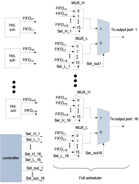
Figure 5. Multi-class scheduler architecture.
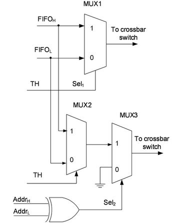
Figure 6. HoL scheduler architecture.
transfer cell from FIFOL when the destination address for high class (AddrH) is different from destination address for low class (AddrL). Mux2 will eliminate the HoL blocking effect for loss sensitive class and will increase the switch performance.
Figure 7 illustrates an example of the scheduler process. Output port 1 will be accepting cell either from input
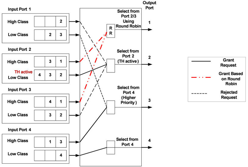
Figure 7. Scheduler example.
port 2 or 3, based on round robin selection since port 2 and 3 cell has the same priority level. Output port 2 will be accepting cell from input port 2 since it has the active threshold. Output port 3 will be accepting cell from input port 4 since it has the higher-priority level then input port 1. Lastly, output port 4 will pass through the cell from input port 4 since it doesn’t have any contention with other cells.
7. Simulation Model
Simulation models are developed to simulate the performance of the proposed scheduling algorithm. In this simulation, the architecture used is 4 × 4 non-blocking switch with two-class priority for every input port. Class 0 is use to classify the low-priority buffer for non-realtime data. At the same time, Class 1 will represent the high-priority buffer for real-time data. The proposed switch operates in time slotted transmission to process each cell. Each time slot consists of three phases that are arrival, scheduler and departure.
7.1. Uniform
In uniform traffic, the traffic loads are equally distributed to all port. Figure 8 illustrates the uniform traffic simulation model.
7.2. Non-Uniform
In non-uniform traffic, the traffic loads are not equally distributed to all port. Figure 9 illustrates the non-uniform traffic simulation model. In this scenario, all the arrival cells are destined to a group of ports in the switch. In this case, the Community-of-interest COI size is limited to 4 output ports, and all the input cells are destined to this COI.

Figure 8. Uniform simulation model.
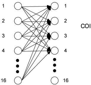
Figure 9. Non-uniform simulation model.
8. Analysis
In order to evaluate the performance of the proposed switch architecture, the analysis is done on the total mean delay with different threshold setting. The delay is calculated based on the assumption that those arrival cells in a slot are independent and identically distributed Bernoulli processes.
In hardware analysis, this total delay for each cell, D can be defined as time for one cell being processed in the system from arrival to departure. This is shown in Equation (10) with Tin is the arrival time of cell, and Tout is the cell departure time.
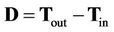 (10)
(10)
Then, the mean delay for single port Class C priority, DPC can be calculated as expressed in Equation (10) with Lc is the total number of cells for Class C priority.
By using data from Equation (11), the total mean delay for the whole system with N number of node, E(D) can be calculated as in Equation (12).
 (11)
(11)
 (12)
(12)
The threshold setting for both parameters will influence the delay performance of the system. Probability on threshold serving low priority cell (PTSC0) can be defined as the amount of delay allowed for the low-priority cell which is based on the delay requirement. The number of queue cell (Nb) can be defined as the minimum traffic load that needs to be adjusted.
The probability of threshold serving class can be calculated as expressed in Equation (13) with PTSC0 is the probability of threshold serving Class 0, TP is the threshold value in integer, and R is the size of a random number generator.
 (13)
(13)
The threshold value, TP must be larger than 2R/2 to ensure the serving probability for Class 1 is better than Class 0.
9. Performance Results
Hardware design using verilog code is develop to evaluate the performance of the proposed architecture. The hardware simulation result is used to obtain the total delay for each cell in Equation (10). Later, the result is used by the Matlab code to calculate the total mean delay in Equation (12) in order to show the performance of the switch.
In order to compare scheduling performance of the multi-class switch in terms of total mean delay, the switch is tested under uniform and non-uniform traffic. The result shows the comparison of mean delay between.
· WFQ which is able to serve Class 1 traffic first due to its priority compared to Class 0.
· Priority classes buffers with the threshold which able to serve Class 0 traffic in the present of Class 1 cells when it is active.
· Proposed scheduling architecture with the ability to serve Class 1 when the threshold for Class 0 is active provided the destination address is different.
Figure 10 shows the total means delay between Class 1 and Class 0 of priority buffer architecture and proposed architecture under uniform traffic with the threshold is set to 250. The Class 1 mean delay for the proposed architecture has great improved compared to priority buffer but slightly higher than WFQ. Meanwhile, for Class 0 mean delay in PQ and proposed architectures only have no different, which is better than WFQ.
Figure 11 shows the total means delay between Class 1 and Class 0 of priority buffer architecture and proposed architecture under non-uniform traffic with the threshold is increased to 4. The Class 1 mean delay for the proposed architecture has great improved compared to priority buffer and slightly higher than WFQ. Meanwhile, for Class 0 mean delay in PQ and proposed architecture have not much different and better than WFQ.
10. Conclusion
The simulation results have shown that dual threshold setting has reduced the total mean delay for the low-priority cell (Class 0) and at the same time minimized the delay increment for the high-priority cell (Class 1) under non-uniform traffic. The number of queued cell (Nb) defines the minimum traffic load that needs to be adjusted. The values of Nb are different depending on the type of traffic.
Probability on threshold serving low priority cell (PTSC0) value defines the amount of delay allowed for the low-priority cells which is based on the delay requirement of the high-priority cells. The PTSC0 parameter will increase the serving probability for Class 0 cells. By combining both parameters, the threshold setting can define the traffic load to start serving low priority cell and the permitted variation delay.
The proposed multi-class with new scheduling technique intent to improve Class 1 performance during the activation of threshold for Class 0. The simulation shows that performance improvement in terms of mean delay on proposed architecture is better compared to priority switch
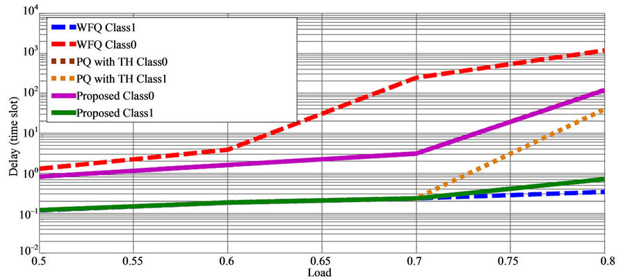
Figure 10. Uniform traffic with threshold is set to Nb =250, PTSC0 = 60%.
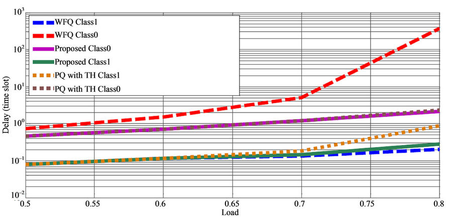
Figure 11. Non-uniform traffic with threshold is set to Nb = 4, PTSC0 = 60%.
with threshold and WFQ.
REFERENCES
- A. K. Gupta and N. D. Georganas, “Priority performance of ATM packet switches,” Proceedings of Eleventh Annual Joint Conference of the IEEE Computer and Communications Societies, Florence, 4-8 May 1992, pp. 727- 733.
- L. Lemin, et al., “Maximum Throughput of an Input Queueing Packet Switch with Two Priority Classes,” IEEE Transactions on Communications, Vol. 42, No. 12, 1994, pp. 3095-3097. doi:10.1109/26.339828
- A. A. A. Rahman, et al. “Multi-Class Scheduling Technique Using Dual Threshold,” The 8th Asia-Pacific Symposium on Information and Telecommunication Technologies, Kuching, 15-18 June 2010, pp. 1-5.
- J. S. C. Chen and R. Guerin, “Performance Study of an Input Queueing Packet Switch with Two Priority Classes,” IEEE Transactions on Communications, Vol. 39, No. 1, 1991, pp. 117-126. doi:10.1109/26.68282
- J. S. Choi and C. K. Un, “Delay Performance of an Input Queueing Packet Switch with Two Priority Classes,” IEE Proceedings of Communications, Vol. 145, No. 3, 1998, pp. 141-144. doi:10.1049/ip-com:19981931
- D. C. W. Pao and S. P. Lam, “Cell Scheduling for ATM Switch with Two Priority Classes,” IEEE ATM Workshop Proceedings, Fairfax, 26-29 May 1998, pp. 86-90.
- A. Al-Sawaai, I. Awan and R. Fretwell, “Analysis of the Weighted Fair Queuing System with Two Classes of Customers with Finite Buffer,” International Conference on Advanced Information Networking and Applications Workshops, Bradford, 26-29 May 2009, pp. 218-223.
- A. Al-Sawaai, I. U. Awan and R. Fretwell, “Performance of Weighted Fair Queuing System with Multi-Class Jobs,” The 24th IEEE International Conference on Advanced Information Networking and Applications, Perth, 20-23 April 2010, pp. 50-57.
- A. A. A. Rahman, et al., “Adaptive Dual Threshold MultiClass Scheduling for Packet Switch,” International Journal of Computer and Network Security, Vol. 2, No. 8, 2010, pp. 21-26.