Int'l J. of Communications, Network and System Sciences
Vol.3 No.2(2010), Article ID:1264,3 pages DOI:10.4236/ijcns.2010.32017
Design and Measurements of Ultra-Wideband Antenna
Physics Department, University of Ioannina, Ioannina, Greece
Email: gtatsis@grads.uoi.gr, vraptis@grads.uoi.gr, kostarakis@uoi.gr
Received October 17, 2009; revised November 21, 2009; accepted November 29, 2009
Keywords: UWB, Antenna, CPW, CDM
Abstract
This paper describes the design, realization and experimental measurements of an antenna element to operate at ultra-wideband (UWB) spectrum. The type of this antenna is a circular disk monopole (CDM), with two notches opposite to each other at two sides of the disk. The feed of the antenna is a coplanar waveguide (CPW). The effect of the presence of the notches is studied through simulations and tested experimentally.
1. Introduction
In every wireless telecommunication system, antennas are some of the most essential elements that characterize the system. Antennas are responsible for effective propagation of electromagnetic energy from transmitter to receiver through the wireless channel. Design and implementation of antennas varies from system to system, depending on the special characteristics of the antennas, such as spectrum occupancy, transmitting power level, directionality, etc. The optimum design of an antenna, to meet those characteristics, has become a great challenge, especially in new technologies like Ultra-Wideband (UWB) technology. In an UWB system a very large spectrum bandwidth must be used. By definition [1], a transmitting signal is considered as UWB if the absolute bandwidth spectrum, at -10dB, exceeds 500MHz or the fractio nal bandwidth is greater than 20%. The Federal Communications Commission (FCC), released a spectrum from 3.1GHz to 10.6GHz, to be used in such a system, with the maximum power density of -41.3 dBm/M-Hz. This is the area of interest that concerns the UWB antennas. Important efforts have been made [2–5], in the design of such antennas. In this paper a modified coplanar feed circular disk monopole (CPW-CDM), is studied and constructed. At the sides of the printed disk two symmetrical notches are placed. It is shown that this modification affects the performance of the antenna significantly. Measurements of the constructed antennas and simulations are presented.
2. Description
Figure 1, shows the geometry of the antenna. A single metallic layer is used upon a substrate of dielectric. This type of antennas is very easy to be constructed, low cost and suitable for portability due to its small size. It consists of a coplanar waveguide in which a sma connector is attached, a circular disk, truncated symmetrical with two notches, and a ground plane, all printed at the same layer. The coplanar waveguide is designed to have 50 Ohm impedance to match the coaxial cable impedance. This impedance is controlled by the two parameters W and G, the width of the feed line and the gap between line and ground plane respectively. The most critical parameters, affecting the performance of this antenna [2], are the disk radius R, the distance H between the disk and the ground plane and the width X of the ground plane. The aforementioned parameters of the constructed antenna are given in Table 1. The modification of the known CPW-CDM antenna that took place in our design is the truncation of the circular disk as shown in Figure 1 by two symmetrical notches. The depth of the two notches is controlled by the variable A.
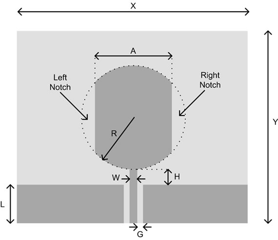
Figure 1. UWB antenna schemat.
3. Fabrication and Results
In order to test the performance of the antenna and to study the effect of the notches four antennas were fabricated using printed circuit techniques, one without notches and three with variable notch depth. The disk diameter was 36mm and the variable A took the values, 32mm, 28mm and 24mm. The dielectric substrate is an FR4 epoxy with relative permittivity of 4.6 and 1.5mm thickness. We used these values to calculate the width and gap of the coplanar feed to match the 50 Ohm impedance of the coaxial cable. The calculated impedance of the transmission line using the values of Table 1, is found to be 50.4 Ohm. For the measurement tests a network analyzer was used and we evaluate the performance of the antennas by measuring the reflection coefficient S11. The results are shown in Figure 2. One can see that the presence of the notches is affecting the reflection coefficient of the antenna. S11 increases at lower frequencies, between 2-5GHz but the peak around 5GHz decreases. One could use that effect to exploit a less frequency selective region, for example between 2-6GHz for the rhomb marked curve. For better distinction of this effect we depict the initial antenna’s S11 and the one’s with A=28mm in Figure 3. In some cases as for Ultra Wideband Impulse Radio less frequency selectivity introduce less pulse distortion which is very significant in this technology. Furthermore a series of simulation were done to have a comparison with the experimental results. The simulation software used, manages frequency domain calculations of the electromagnetic equations utilizing the method of moments. The simulated return loss is shown in Figure 4. We can notice that the results are fairly consistent with the measurements. In addition we have the opportunity to investigate the whole spectrum, released by the FCC (3.1GHz-10.6GHz). The spectrum from 9GHz to 11GHz was not measured experimentally since the maximum frequency of the network analyzer used was 9GHz. By checking both results it is reasonable to assume that the antenna in fact doesn’t exceed the -10dB limit in the region between 9GHz-10.6GHz.
4. Conclusions
A modified coplanar waveguide circular disk monopole antenna, for ultra wideband applications was described in this article. The effect of two symmetrical notches of the circular disk was under investigation. The impact of the truncated monopole was calculated with simulations using the method of moments and compared with the measured results. Measurements results show that the antenna has an ultra-wideband performance with reflection coefficient less than-10dB in the range 2.2-9Ghz. Simulations have shown a good agreement with measurements and an acceptable S11 performance below -10dB in range
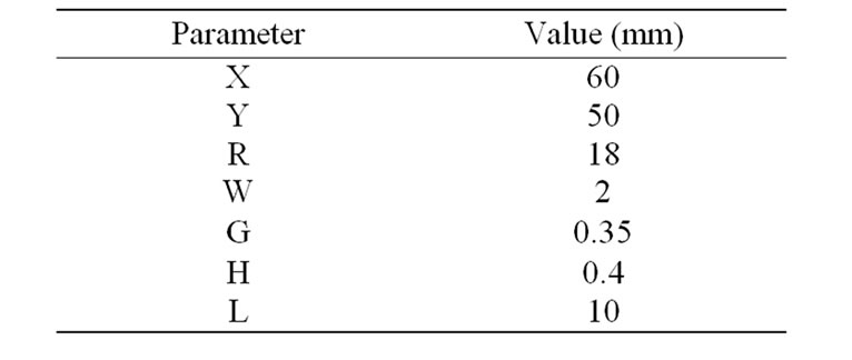
Table 1. Antenna parameters.
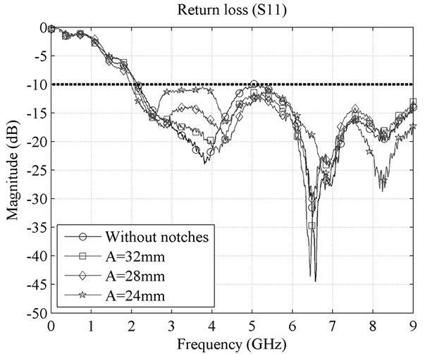
Figure 2. Measured return loss of antennas.
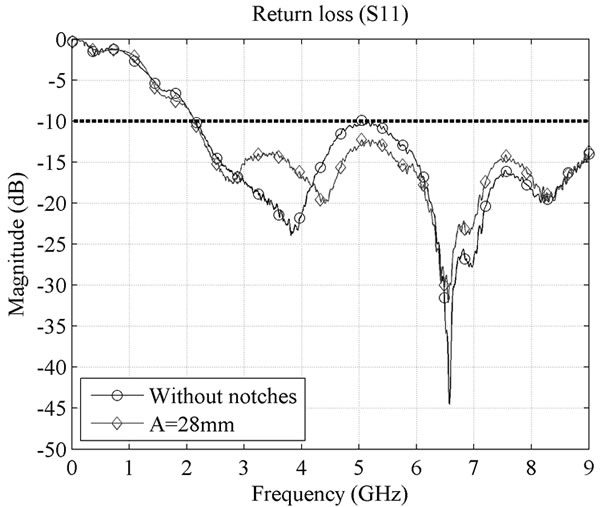
Figure 3. Return loss comparison of the antenna without notches and the one with A=28mm.
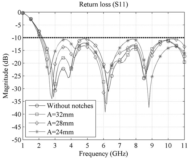
Figure 4. Simulated return loss of antennas.
2.2-11GHz. From this study we concluded that the modified antenna leads to less signal distortion of ultra wideband pulses.
5. Acknowledgment
This research project (PENED) is co-financed by E.U.-European Social Fund (80%) and the Greek Ministry of Development-GSRT (20%).
6. References
[1] L. Q. Yang and G. B. Giannakis, “Ultra-wideband communications,” IEEE Signal Processing MagazineNovember 2004.
[2] J. X. Liang, L. Guo, C. C. Chiau, and X. D. Chen, “CPW-fed circular disc monopole antenna for UWB applications,” IEEE 2005, pp. 505–508.
[3] Z. N. Low, J. H. Cheong, and C. L. Law, “Low-cost PCB antenna for UWB applications,” IEEE Antennas and Wireless Propagation Letters, Vol. 4, 2005.
[4] Y. Kim and D. H. Kwon, “CPW-fed planar ultra wideband antenna having a frequency band notch function,” Electronics Letters, Vol. 40, April 2004.
[5] J. Jung, W. Y. Choi, and J. Choi, “A compact broadband antenna with an L-shaped notch”, IEICE Transactions on Communications, Vol. E89-B, No. 6, June 2006.