Int'l J. of Communications, Network and System Sciences
Vol.2 No.6(2009), Article ID:689,11 pages DOI:10.4236/ijcns.2009.26051
Beam Pattern Scanning (BPS) versus Space-Time Block Coding (STBC) and Space-Time Trellis Coding (STTC)
Department of Electrical and Computer Engineering, Michigan Technology University, Houghton, Michigan, USA
Email: {rezaz, pteh}@mtu.edu
Received April 2, 2009; revised June 10, 2009; accepted July 22, 2009
Keywords: Antenna Array, Beam Pattern Sweeping, Transmit Diversity, Space-Time Block Codes, and Space-Time Trellis Coding.
ABSTRACT
In this paper, Beam Pattern Scanning (BPS), a transmit diversity technique, is compared with two well known transmit diversity techniques, space-time block coding (STBC) and space-time trellis coding (STTC). In BPS (also called beam pattern oscillation), controlled time varying weight vectors are applied to the antenna array elements mounted at the base station (BS). This creates a small movement in the antenna array pattern directed toward the desired user. In rich scattering environments, this small beam pattern movement creates an artificial fast fading channel. The receiver is designed to exploit time diversity benefits of the fast fading channel. Via the application of simple combining techniques, BPS improves the probability-of-error performance and network capacity with minimal cost and complexity.In this work, to highlight the potential of the BPS, we compare BPS and Space-Time Coding (i.e., STBC and STTC) schemes. The comparisons are in terms of their complexity, system physical dimension, network capacity, probability-of-error performance, and spectrum efficiency. It is shown that BPS leads to higher network capacity and performance with a smaller antenna dimension and complexity with minimal loss in spectrum efficiency. This identifies BPS as a promising scheme for future wireless communications with smart antennas.
1. Introduction
Transmit diversity schemes use arrays of antennas at the transmitter to create diversity at the receiver. Different transmit diversity techniques have been introduced to mitigate fading effects in wireless communications [1–5]. Examples are space-time block coding [1–3], space-time trellis coding [3–5], antenna hopping [6] and delay diversity [6,7].
In Space-Time Block Coding (STBC), data is encoded by a channel coder and the encoded data is split into N unique streams, simultaneously transmitted over N antenna array elements. At the receiver, the symbols are decoded using a maximum likelihood decoder. This scheme combines the benefits of channel coding and diversity transmission, providing BER performance gains. However, receiver complexity increases as a function of bandwidth efficiency [3] and requires high number of antennas to achieve high diversity orders. Moreover, antenna elements should be located far enough to achieve space diversity and when antenna arrays at the base station (BS) are used in this fashion, directionality benefits are no longer available [1–3]. This reduces the network capacity of wireless systems in terms of number of users.
In Space-Time Trellis Coding (STTC) information symbols are encoded by a unique space-time channel coder and the encoded information symbols are split into N unique streams, simultaneously transmitted over N antenna arrays elements. At the receiver, after receiving a block of symbols denoted by frame (e.g., 130 symbols per frame), Viterbi algorithm is used to recover and error-correcting the information symbols in the frame [3–5]. This scheme combines the benefits of space diversity and coding gain, providing a significant probability-of-error performance gain. However, the receiver complexity increases exponentially as a function of number of trellis states (transmit antennas); and, in general, high order of trellis states (transmit antennas) are required to achieve high diversity and coding gain [8,9]. Moreover, similar to STBC, in STTC antenna array elements should be located far enough to achieve space diversity which reduces STTC network capacity in terms of number of users.
BPS has been introduced as a powerful transmit diversity technique capable of enhancing both wireless network capacity and probability-of-error performance with minimal cost [10–13]. In this scheme, antenna elements located at the distance of half a wavelength form an antenna array. These antenna arrays are mounted at the BS. They are incorporated to create directional beams steered toward the desired users. Time varying phase shifts are applied to antenna elements to move the antenna pattern within the symbol duration Ts. The antenna pattern starts from a point in space at time zero, sweeps an area of space from time 0 to Ts, and returns back to its initial position after time Ts, and repeats similar sweeping again. The beam pattern movement is small, e.g., in the order of 5% of half power beam width (HPBW). Simulations in [10] has shown that in rich scattering environments, BPS leads to a time varying channel with a small coherence time Tc with respect to Ts. This generates an artificially created fast fading channel leading to a time diversity that can be exploited at the receiver [10,11]. Hence, BPS leads to: a) high performance via time diversity, and b) high network capacity (in terms of number of users) via directionality inherent in BPS.
Here, BPS is compared with STBC and STTC schemes with their antenna replaced by directional antenna arrays (without scanning) [9] in order to achieve directionality (i.e., Spatial Division Multiple Access (SDMA) benefit) available in BPS. The elements of comparison are: 1) probability-of-error (bit-error-rate, BER, and frame-error-rate, FER) performance, 2) network capacity, 3) system complexity (in terms of physical dimension), and 4) bandwidth efficiency.
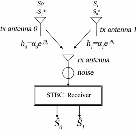
Figure 1. Space-time block codes system (N = 2)
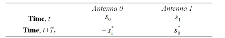
Table 1. STBC structure for (N=2).
The results confirm that BPS scheme leads to higher network capacity and BER/FER performance and lower complexity. However, BPS technique relative spectral efficiency is less than STBC and STTC, e.g., in the order of 5%. In other words, BPS technique offers higher quality-of-service and network capacity with a minimal cost of spectrum efficiency. This introduces BPS as a powerful scheme for future generation of wireless communications with smart antenna arrays.
Section 2 introduces STBC, STTC and BPS schemes. Section 3 compares their characteristics and, Section 4 presents and compares their capacity and BER/FER performance simulations. Section 5 concludes the paper.
2. Introduction of STBC, STTC and BPS Techniques
Here, we briefly introduce the fundamentals of the three techniques, STBC, STTC and BPS.
2.1. STBC
STBC is a transmit diversity technique capable of creating diversity at the receiver to improve the performance of communications systems. STBC utilizes N transmit antennas separated far apart to ensure independent fades [1,2]. At a given symbol period, N signals are transmitted simultaneously from N antennas. The signal transmitted from each antenna has a unique structure that allows the signal to be combined and recovered at the receiver. For simplicity in presentation, we only consider STBC with 2 transmit antennas (N = 2) (see Figure 1).
We consider s0 and s1 two consecutive signals generated at two consecutive times t0 and t1 = t0+Ts, respectively. The signal transmitted from antenna zero is denoted by s0 and the one from antenna one is denoted by s1. At the next symbol period, the transmitted signal from antenna zero is  and the signal transmitted from antenna one is
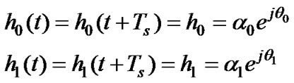
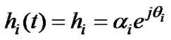
  where * is the complex conjugate operation (see Table 1). The channel is denoted by h0 for transmit antenna 0 and h1 for transmit antenna 1. The main assumption here is that the fading is constant across two consecutive symbols (i.e., over t and t1 = t +Ts, t Î [0,Ts]); we can represent the channel fading for antenna 0 and 1 as:
 (1)
(1)
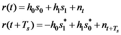
respectively, where Ts is the symbol duration, ai, qi, i Î {0,1} are the Rayleigh fading gain and phase, respectively. The received signal at time t and t + Ts, corresponds to
 (2)
(2)
respectively. Here, nt and  are complex random variables representing receiver noise and interference at time t and t + Ts, respectively.
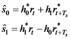
In the STBC receiver, Maximal Ratio Combining (MRC) leads to an estimation of s0 and s1, corresponding to:
 (3)
(3)
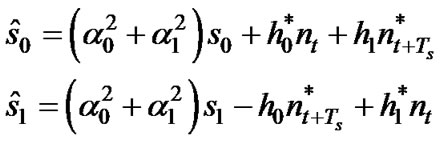
respectively (note: rt=r(t)). Substituting (1) and (2) into (3), we obtain
 (4)
(4)
In other word, a maximum likelihood receiver leads to the removal of the s1 and s0 dependent terms in ŝ0 and ŝ1, respectively. This generates a high probability-of-error performance at the receiver.
2.2. STTC Technique
STTC is a transmit diversity technique that combines space diversity and coding gain to improve the performance of communication systems [3,5,8]. STTC utilizes N transmit antennas separated far apart to ensure independent channels. At a given symbol period, N signals are transmitted simultaneously from N antennas. The signal transmitted from each antenna has a unique structure with inherent error-correction capability to allow signal to be recovered and corrected at the receiver [8]. In this paper, we only consider the simulation scenario presented in [3], that is p/4-QPSK, 4-states, 2 b/s/Hz STTC (hereafter, denoted as STTC-QPSK) that utilizes two transmit antennas and one receive antenna.
The trellis structure of STTC-QPSK is shown in Figure 2(a) and the constellation mapping in Figure 2(b). In STTC-QPSK, information symbols are encoded using a channel coder by mapping input symbols to a vector of output (codewords) based on a trellis structure (Figure 2(a)). Here, information symbols are encoded based on the current state of the encoder and the current information symbols. Thus, the encoded codewords are correlated in time.
At the left of the trellis structure (Figure 2(a)) are the STTC codewords (s1,s2), s1,s2 Î {0,1,2,3}. In Figure 2(a), there are four emerging branches from each trellis state, because there are four possible QPSK symbols, namely {0,1,2,3}. For example, consider the space time trellis coder that starts at state (q1,q2) = (0,0) (represented by 00). When the information symbol is 10, the coder transition from state 00 to 10 produces the output code-words (s1,s2) of (0,2). When the next information symbol is 11, the coder transition from state 10 to 11 produces the output codeword (2,3). The channel coder continues to change from its current state to a new state based on the incoming information symbols. Based on the design, the channel coder resets to state 0 after completing the coding of a frame (e.g., 130 symbols). The output code-words of the encoder is then mapped into a p/4-QPSK constellation (Figure 2(b)). The mapping results in two information symbols. Each information symbol is then transmitted on each antenna simultaneously. Through this encoding scheme, redundancy is introduced into the system but at the same time, the symbols are transmitted over two antennas. Therefore, coding redundancy does not impact the throughput. In order to achieve SDMA to improve network capacity, each STTC-QPSK antenna element is replaced with one antenna array [9] to generate two static beams directed toward the desired users (Figure 3).
The channel is denoted by h0 for transmit antenna 0 and h1 for transmit antenna 1. We represent the channel fading for antenna i, i Î {0,1} as:
 (5)
(5)
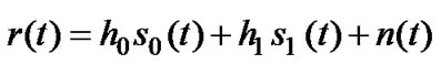
respectively, where ai, qi, i Î {0,1} are the Rayleigh fading gain and phase, respectively. The received signal at time t can be modeled as
 (6)
(6)
where si(t) is the transmitted symbol and n(t) is the complex random variable representing receiver noise at time t. The receiver is designed using Viterbi algorithm. The branch metric for a transition labeled q1(t) q2(t) corresponds to [3]
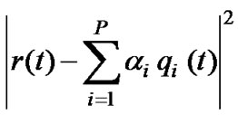 (7)
(7)
where P is the number of transmit antenna. Viterbi algorithm is used to compute the path with the lowest accumulated metric [3].
2.3. BPS
BPS is a new transmit diversity technique utilizing an antenna array to support directionality and transmit diversity via carefully controlled time varying phase shifts applied to each antenna element. This creates a slight motion of the beam pattern directed toward the desired users [10]. Beam pattern movement creates an artificial fast fading environment that leads to time diversity exploitable by the BPS receiver [11]. Beam pattern move-
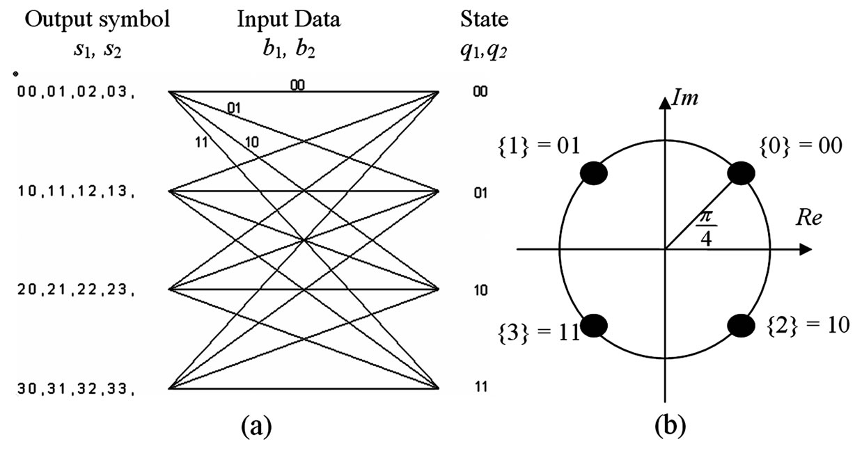
Figure 2. (a) STTC-QPSK trellis structure, and (b) Constellation mapping using gray code
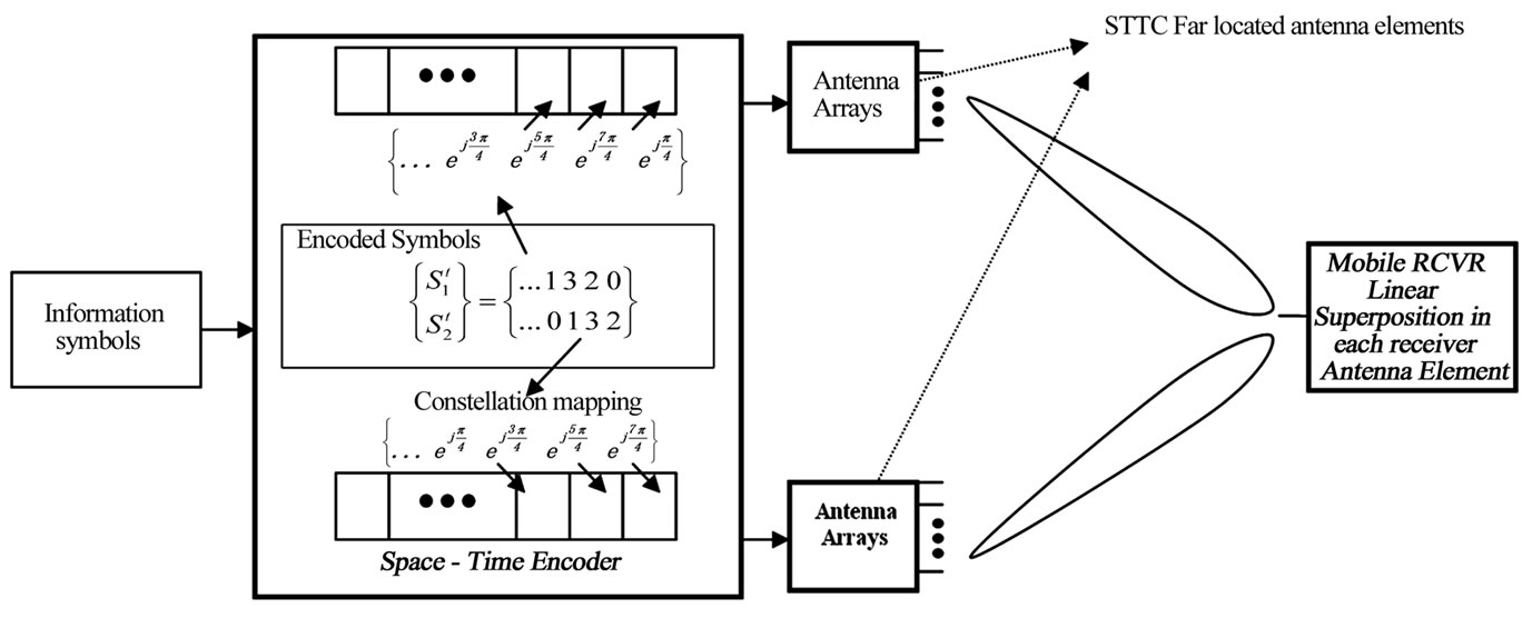
Figure 3. STTC far located antenna elements are replaced by antenna arrays to support SDMA.
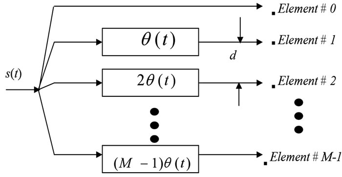
Figure 4. Antenna array structure.
ment is created by applying time varying phase q(t) to the elements of antenna array (see Figure 4).
In BPS, the beam pattern sweeps an area of space within Ts (symbol duration) and returns to its initial position and starts moving again. Properly selecting the phase offset q(t) leads to a movement of antenna beam pattern that ensures: 1) constant large scale fading over Ts, and 2) the generation of L independent fades within each Ts.
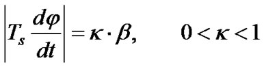
1) Achieving constant large-scale fading: In order to ensure constant large-scale fading over each symbol period Ts, the mobile must remain within the antenna array’s HPBW at all times. This corresponds to
 (8)
(8)
where b is the HPBW, φ is the azimuth angle, dφ / dt is the rate of antenna pattern movement, and Ts·(dφ / dt) is the amount of antenna pattern movement within Ts. The received antenna pattern amplitude is ensured to remain within the HPBW for the entire symbol duration, Ts, using the control parameter k, 0 < k < 1.
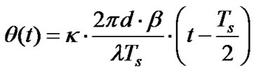
2) Achieving L independent fades within each Ts: Using (8), the phase offset applied to the antenna array is found to be (see [3,6,7]):
 (9)
(9)
where l is the wavelength of the carrier and d is the distance between adjacent antenna elements.
The sweeping of the beam pattern creates an artificial fast fading channel with a coherence time that may lead to L independent fades over Ts. This is a direct result of the departure and the arrival of scatterers within the antenna array beam pattern window. Simulation results in [10] and [11] assuming a medium size city center, with 0.0005 < k < 0.05, reveals that time diversity gains as high as L = 7 is achievable using BPS scheme.
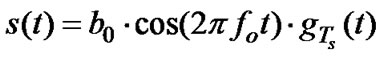
Assuming BPSK modulation, the transmitted signal can be represented as
 (10)
(10)
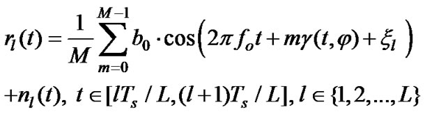
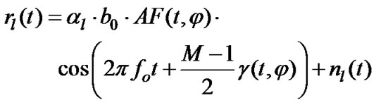
where b0 Î {–1,+1} is the transmitted bit, fo is the carrier frequency, and gTs(t) is the pulse shape (e.g., a rectangular waveform with unity height over 0 to Ts). The normalized signal received at the mobile receiver input corresponds to:
 (11)
(11)
where m Î {0,1,2,…, M–1} is the mth antenna array element (Figure 2), nl(t) is an additive white Gaussian noise (AWGN), which is considered independent for different time slots (l), al is the fade amplitude in the lth time slot, and xl is its phase offset (hereafter, this phase offset is assumed to be tracked and removed). Moreover, in (11),
 (12)
(12)
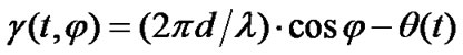
where (2pd/l)×cosφ is the phase offset caused by the difference in distance between antenna array elements and the mobile (assuming the antenna array is mounted horizontally), and θ(t) is introduced in Equation (9). Applying the summation over m, Equation (11) corresponds to
 (13)
(13)
Here,
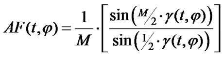 (14)
(14)
is the antenna array factor. Assuming the mobile located at φ = p/2, (12) can be approximated by g(t, φ) = g(t) = -q(t). Moreover, assuming that antenna array’s peak is directed towards the intended mobile at time 0, and small movements of antenna array pattern over Ts, i.e., in Equation (9), k is small, the array factor is well approximated by AF(t, φ) @ 1.
The time varying phase of (9) in (12) and (13) leads to a spectrum expansion of the transmitted (and the received) signal. Because the parameter k in (9) is considered small (e.g., k = 0.05), this expansion is minimal (see Subsection 3.2). After returning the signal to the base-band the received signal corresponds to:
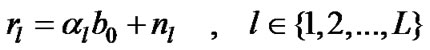 (15)
(15)
3. BPS versus STBC, STTC
STBC, STTC and BPS are compared in terms of physical antenna dimension, complexity, spectrum efficiency, network capacity and BER performance.
3.1. Complexity and Physical Antenna Dimension
The main complexity of BPS scheme is at the transmitter mounted at the BS to generate a time varying beam pattern directed toward the desired user, whereas, the complexity of STBC scheme is mainly due to the number of transmitting antennas, N, at the BS and the combining scheme at the receiver [3].
The complexity of STTC scheme is mainly due to both the encoder (transmitter) and decoder (receiver). The encoding process requires a space-time channel coder to encode the information symbols according to a specific trellis structure (e.g., Figure 1). The decoding complexity that utilizes Viterbi algorithm increases exponentially with the number of states (transmit antennas) of the trellis structure [3].
Here, we consider:
1) Space-Time Coding (STC) techniques (i.e., both STBC and STTC) use two antenna arrays to generate directional beam pattern: a) Each antenna array contains six antenna elements (each element is separated by lo / 2), and b) The antenna arrays are separated far enough (e.g., by 5lo) to ensure independent fades. Here, lo is the wavelength of the carrier frequency (or the average wavelength of all carrier frequencies if multi-carrier transmission is used).
2) BPS technique uses: a) a single 6-element antenna array (elements are separated by lo/2), and b) Beam-pattern movement is assumed to result in up to seven fold diversity (in general, a function of parameter k) [10].
STC schemes’ antenna dimension is higher than BPS since STBC scheme utilizes 2 antenna arrays (in general, any number of antenna arrays). Considering, antenna array elements are separated by lo/2, the length of the antenna array would be 2.5lo. To ensure independent fades, these antennas should be located apart enough (e.g., 5lo). This leads to the total length of 10lo for STBC antenna array while BPS needs just 2.5lo length antenna array. Thus, the physical antenna dimensions of STC techniques are much greater than the antenna array dimensions for BPS scheme. Moreover, STTC physical antenna array dimensions (specifically, with each antenna element replaced by an antenna array) increase as the number of antenna arrays increases.
Antenna array pattern characteristics (e.g., its HPBW) changes with frequency [12,13]. Hence, in wideband multi-carrier systems, (e.g., in multi-carrier code division multiple access, MC-CDMA, or orthogonal frequency division multiplexing (OFDM) systems) each group of sub-carriers might be required to be transmitted over unique antenna arrays in order to create an ideal SDMA; and hence, a number of antenna array clusters or antenna array vector clusters are required (see [12,13] for more information). In this case, the complexity and the dimensions of STBC and STTC are much higher than BPS scheme. In general, the dimensions (and, as a result, the complexity) of STC schemes increase as the number of antenna arrays increases. In addition, the complexity of STTC increases as the number of trellis states increases and as a result the required number of antenna arrays increases (in order to create higher orders of space diversity and coding gain).
3.2. Spectrum Efficiency and Throughput
BPS technique creates a bandwidth expansion as it is discussed in the previous section, while STBC scheme with static beam patterns does not generate this expansion. BPS system bandwidth is expanded by a factor corresponds to
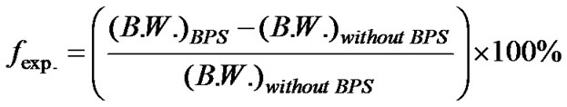 (16)
(16)
where (B.W.)BPS = bandwidth needed with BPS and (B.W.)withoutBPS = bandwidth needed without BPS. Considering (13) and using (12) and (9), the expansion factor fexp. corresponds to
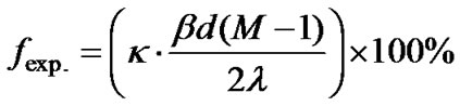 (17)
(17)
Hence, with a constant Ts, l, b, d and M, for both BPS and STBC systems, the relative reduction in bandwidth efficiency due to BPS corresponds to
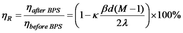 (18)
(18)
Considering d = l/2, and typical values of b (e.g., b = 0.5 rad.), and M = 6, (18) can be approximated by
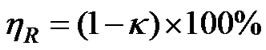 (19)
(19)
With this definition, the relative reduction in BPS spectrum efficiency is determined by the control parameter, k. For example, considering k = 0.05 (an antenna sweeping is equivalent to 5% of HPBW), hR = 95%. On the other hand, with a constant bandwidth available to both BPS, and STBC and STTC, the throughput of BPS is less than STC techniques by the factor fexp. (e.g., by a factor of less than 5%). This disadvantage of BPS is very minimal with respect to advantages of BPS techniques as discussed in this paper.
3.3. Capacity and Performance
In this paper, we have assumed the same antenna arrays (with the same HPBW and approximately the same dimension and complexity) for both BPS and STC systems. This assumption leads to higher order of diversity via BPS compared to STC (e.g., up to 7 fold diversity in BPS versus 2 fold diversity in STC), which better mitigates fading effects in BPS system compared to STC systems. Hence, while this leads to a higher probability-of-error performance in BPS systems, considering a constant signal power to noise power ratio, it leads to a higher network capacity as the number of users’ increases. The details of capacity and performance enhancements are presented in the next section via simulations.
4. Simulations
4.1. BER Performance Simulations
Simulations are performed assuming:
a) Mid-size city center (e.g., 3 scatterers per 1000m2) that leads to 7 fold diversity with BPS technique;
b) BPSK transmission for STBC and BPS comparison and QPSK transmission for STTC and BPS comparison;
c) One received antenna;
d) Switched beam smart antenna arrays (with HPBW = 18o) are mounted at the BS;
e) Quasi-static channel, i.e., channel characteristic is static over 2 consecutive symbol periods, Ts, for STBC and over the entire frame, for STTC-QPSK and then changes in an independent manner; and
f) STTC-QPSK frame is equal 130 symbols.
For simplicity of comparison and to illustrate the benefits of time diversity induced by BPS scheme, Equal Gain Combining (EGC) over time components is assumed. EGC technique does not rely on channel estimation to perform the combining. The performance simulations for STBC compared to BPS are shown in Figure
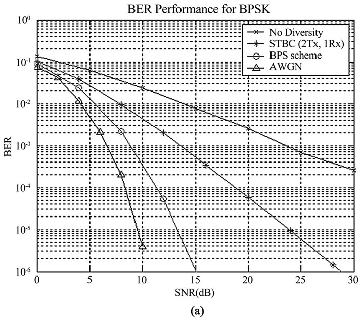
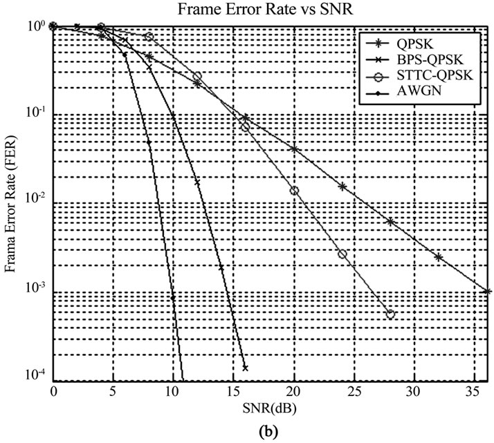
Figure 5. BER/FER performance comparing (a) STBC versus BPS scheme, and (b) STTC-QPSK versus BPS.
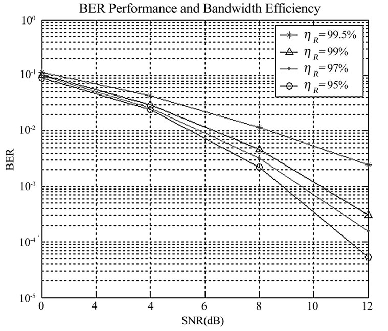
Figure 6. BPS performance for different hR values.
5(a). It can be observed that BPS scheme offers 5 dB and 15 dB improvement in performance at probability-of-error 10-3 compared to STBC scheme and traditional BPSK system without diversity, respectively. The performance improvement in BPS scheme is due to the high order of time diversity gains achieved through beam pattern movement. The diversity order achievable via STBC is lower than BPS, and, therefore, its BER performance is lower compared to BPS scheme.
The performance simulations for BPS versus STTC-QPSK are shown in Figure 5(b). It is observed that BPS scheme offers 12 dB and 22 dB improvements in performance at probability-of-error 10-3 compared to STTC-QPSK scheme with antenna arrays and without beam pattern movement, respectively. The performance improvement via BPS is the result of high order of time diversity gains achieved through beam pattern movement. Although STTC-QPSK offers both diversity and coding gain, the diversity order offered by STTC-QPSK is much inferior compared to BPS-QPSK; thus, even without coding gain benefit in BPS-QPSK scheme, it surpasses the performance of STTC-QPSK with relatively lower complexity.
In Figure 6, BER performance of BPS system is generated for different relative spectrum efficiency, hR. Increasing the parameter k leads to higher order of diversity that enhances BER performance of the system; and, on the other hand, it reduces BPS relative bandwidth efficiencies. For example, as it is discussed in [10], in a rich scattering environment, k = 0.005 leads to two-fold diversity which is equivalent to hR = 99.5%. Increasing k from 0.005 to 0.05 increases the diversity achievable to 7 folds, and reduces the relative spectrum efficiency to hR = 95%. This is equivalent to a decrease in throughput from 0.5% to 5%.
4.2. Network Capacity Simulations
Network capacity simulations are performed assuming:
a) MC-CDMA transmission with N = 32 carriers;
b) Four fold frequency diversity over the entire bandwidth;
c) For STBC-BPS comparison, we consider inter-cell interference effects from the first tier cells (see Figure 7). This interference is reduced via long codes assigned to signals transmitted to the users of each cell;
d) For STTC-BPS comparison, inter-cell interference effects are ignored, (see Figure 7);
e) Mid-size city center (e.g., 3 scatterers per 1000m2) that leads to 7 fold diversity with BPS technique;
f) Users are distributed uniformly in the cell;
g) Inter-user-interference within the cell is reduced via random assignment of Hadamard-Walsh codes
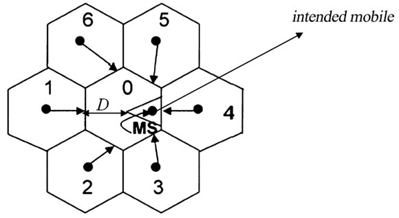
Figure 7. Interfering cells assuming one-tier cellular network. The direction of beam patterns that will interfere with intended mobile is represented.
(in MC-CDMA systems);
h) Equal Gain Combining (EGC) over frequency components;
i) Switched beam smart antenna arrays (with HPBW = 18o) are mounted at the BS; and
j) Signal power to noise power ratio is SNR = 10dB for STBC and SNR = 12dB for STTC.
With these assumptions, the received BPS/MCCDMA signal corresponds to [12]:
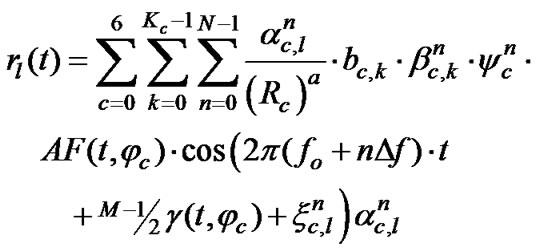 (20)
(20)
Here, AF(t, φc) is the array factor introduced in (14), nl(t) is an additive white Gaussian noise (AWGN), which is considered independent for different time slots (l), bc,kÎ{+1,-1} is the cth cell’s kth user’s transmitted bit,  is the Hadamard-Walsh spreading code for kth user and nth sub-carrier in the cth cell, ycn is the long code of the nth sub-carrier for cth cell,
  is the Rayleigh fade amplitude on the nth sub-carrier in the lth time slot in the cth cell and
  is its phase (which is assumed to be tracked and removed).
  is assumed independent over time components, l, and correlated over frequency components, n [14]. Kc represents the number of users effectively interfere with the desired user.
In the neighboring cells, these users are located at the antenna pattern (sector) with directions shown in Figure 7. Considering assumptions (f) and (i)
 (21)
(21)
when E(·) denotes the expectation and K is the number of users available in each cell. In (20) 1/(Rc)a represents the long-term path loss of the signal received by the mobile (MS) in the cell 0. This signal is transmitted by the BS of neighboring cells to the users located in those cells, and in the directions which interfere with the intended mobile (see Figure 7).
In Figure 7, D is the cell radius. Assuming the intended mobile is located at  and approximating the coverage area by a triangle,
  represents the approximate center of mass of users in the beam pattern coverage area. Rc represents the distance between the BS of the cell c, c Î {0,1,2,…6}, and the intended mobile in the cell 0. From the geometry in Figure 7, vector R formed by the elements Rc, c Î {0,1,2,…6}, corresponds to [12]
R = [1.00 3.83 3.44 1.975 1.83 1.975 3.44] (22)
where R0 is normalized to one and the others are normalized with respect to this value.
In (20), the power factor a is a function of user location, BS antenna height and environment. Considering urban areas, parameter a changes with the carrier frequency and BS antenna height. In urban areas, a = 1, if Rc < Dmax, and a = 2 if Rc > Dmax, where Dmax = D(fo,ha), (Dmax is a function of the carrier freuquency fo and antenna height ha). Considering fo = 900MHz, and BS height, ha > 25m, Dmax ≈ 1000m (see [15]). Assuming a cell of radius D ≈ 500m, and by referring to [15], we find that a = 2 for cells 1, 2 and 6 whereas a = 1 for cells 3, 4 and 5. Thus, in the simulations we ignore the interference from cells 1, 2 and 6 and only consider inter-cell interference from cells 3, 4 and 5 with a little loss in accuracy.
With the model introduced in (20), the received STBC/MC-CDMA signal corresponds to
 (23)
(23)
where bc,k[i] and bc,k[i+1], i Î {0,2,4,…} is the kth user ith information bit in the cth cell for STBC,  and
and  are the Rayleigh fade amplitude due to antenna 0 and antenna 1 in the nth sub-carrier in the cth cell and
  and
and  are their phase, respectively,
  is the HadamardWalsh spreading code for kth user and nth subcarrier, ycn is the long code of the nth sub-carrier in the cth cell, 1/(Rc)a characterizes the long-term path loss and n(t) is an additive white Gaussian noise (AWGN).
Figure 8(a) represents network capacity simulation results generated considering MRC across time compo
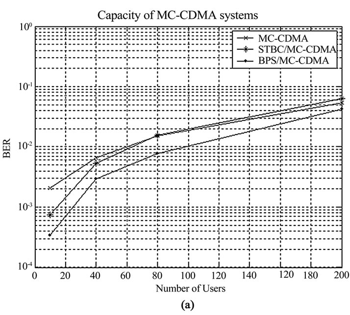
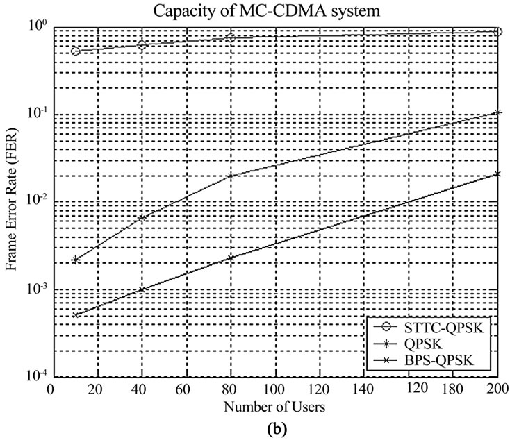
Figure 8. Capacity performance (a) STBC and BPS, and (b) STTC and BPS
nents in BPS and across space components in STBC (see [3] and [4]) and EGC across frequency components in both BPS and STBC. It is observed that a higher network capacity is achievable with BPS/MC-CDMA. For example, at the probability-of-error of 10-2 BPS/MC-CDMA offers up to two-fold higher capacity. It is also observed that STBC/MC-CDMA offers a better performance compared to the traditional MC-CDMA without diversity when the number of users in the cell are less than 80. However, as the number of users in the cell increases beyond 80, the performance of STBC/MC-CDMA becomes even worse than traditional MC-CDMA (i.e., MC-CDMA with antenna array but without diversity benefits). This is because STBC scheme discussed in this paper (see [1]) is designed to utilize MRC. It has been shown that MRC combining scheme is the optimal combining scheme when there is only one user available, while in a Multiple Access environment, MRC enhances the Multiple Access Interference (MAI) and therefore degrades the performance of the system [16].
Considering STTC-QPSK, with assumption (d), STTC-QPSK/MC-CDMA received signal corresponds to
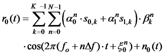 (24)
(24)
Here s0,k and s1,k is the kth user information bit transmitted from antenna 0 and antenna 1, respectively,  and
and  are the Rayleigh fade amplitude due to antenna 0 and antenna 1 in the nth sub-carrier and
  and
and  are their phase, respectively,
  is the Hadamard-Walsh spreading code for kth user and nth sub-carrier, and n(t) is an additive white Gaussian noise (AWGN).
Network capacity simulations for STTC-QPSK are generated assuming EGC across time components (in BPS), space components (in STTC-QPSK) and frequency components for BPS and STTC-QPSK [Figure 8(b)]. Figure 8(b) represents STTC versus BPS-QPSK simulation results. This figure shows that BPS-QPSK is superior compared to STTC-QPSK and QPSK without diversity. In this simulation, BPS-QPSK leads to significantly better capacity due to the time diversity induced by beam-pattern movement and frequency diversity inherent in MC-CDMA. The results also show that QPSK performance is superior compared to STTC-QPSK. This agrees with the FER simulation results in Figure 5(b), where QPSK is better than STTC-QPSK at low SNRs (e.g., at SNR = 10 dB). This is because STTC-QPSK is designed under the assumption of high enough SNR values; thus, it is less efficient compared to QPSK at low SNRs [17]. (The capacity curve for higher SNR values may lead to better STTC-QPSK performance compared to QPSK; however, STTC-QPSK shows a lower performance compared to BPS-QPSK for all SNRs). Thus, it is observed that a higher network capacity is achievable via BPS/MC-CDMA. It is also worth mentioning that STTC-QPSK performance can be significantly improved via interference suppression/cancellation techniques at the cost of system complexity as discussed in [19–21]. In this paper, we conducted the comparison without a complexity added to the STTC scheme via implementing interference suppression algorithms.
Simulations confirm that BPS offers superior network capacity compared to STC schemes; however, there are two issues associated with BPS scheme: 1) diversity achievable via BPS changes with distance; greater the distance of mobile from the BS, higher the diversity and network capacity [10]. It is notable that in general, the average number of users located in constant width annuluses (with BS at the center) increases as the distance from the BS increases; and 2) BPS works just in urban areas (or in rich scattering environments); but, because a high network capacity is only required in urban areas, this is not a critical issue. Moreover, BPS can also be merged with STC techniques, e.g., via the structure shown in Figure 4. In this case, the traditional antenna arrays are replaced with time varying weight vector antenna arrays to direct and move the antenna pattern. Another approach for merging BPS with STBC is introduced in [18].
Nevertheless, it is worth mentioning that BPS scheme achieve the probability-of-error performance and the network capacity benefits with a relatively less complexity. This makes BPS a prominent scheme for future wireless generations with smart antennas. However, the spectrum efficiency of BPS is about 5% less than STC which is a minimal disadvantage compared to the benefits created by BPS technique.
5. Conclusions
A comparison was preformed between STBC, STTCQPSK and BPS transmit diversity techniques in terms of network capacity, BER/FER performance, spectrum efficiency, complexity and antenna dimensions. BER performance and network capacity simulations are generated BPS, STBC, and STTC schemes. This comparison shows that BPS transmit diversity scheme is much superior compared to both STBC and STTC-QPSK schemes: a) The BS physical antenna dimensions of BPS is much smaller than that of STC techniques, and b) The BER/FER performance and network capacity of BPS is much higher than that of STC schemes. The complexity of BPS system is minimal because the complexity is mainly located at the BS, and the receiver complexity is low because all the diversity components enter the receiver serially in time. In terms of spectrum efficiency, both STC schemes outperform BPS scheme by a very small percentage (e.g., in the order of 5%). BPS scheme introduces a small bandwidth expansion due to the movement in the beam pattern that eventually results in a lower throughput per bandwidth.
6. References
[1] S. M. Alamouti, “A simple transmit diversity technique for wireless communications,” IEEE Journal on Selected areas in Communications, Vol. 16, No. 8, pp. 1451–1458, 1998.
[2] V. Tarokh, H. Jafarkhani, and A. R. Calderbank, “Space-time block codes from orthogonal designs,” IEEE Transactions on Information Theory, Vol. 45, No. 5, pp. 1456–1467, July 1999.
[3] V. Tarokh, N. Seshadri, and A. R. Calderbank, “Space-time codes for high data rate wireless communication: Performance criterion and code construction,” IEEE Transactions on Information Theory, Vol. 44, pp. 744–765, March 1998.
[4] V. Tarokh, A. F. Naguib, N. Seshadri, and A. Calderbank, “Space-time codes for high data rate wireless communications: Performance criteria in the presence of channel estimation errors, mobility, and multiple paths,” IEEE Transactions on Communications, Vol. 47, No. 2, February 1999.
[5] A. F. Naguib, V. Tarokh, N. Seshadri, and A. R Calderbank, “A space-time coding modem for high-data-rate wireless communications,” IEEE Journal on Selected Areas in Communications, Vol. 16, No. 8, October 1998.
[6] N. Seshadri and J. H. Winters, “Two signaling schemes for improving the error performance of frequency division-duplex transmission system using transmitter antenna diversity,” International Journal Wireless Information Networks, Vol. 1, No. 1, pp. 49–60, January 1994.
[7] J. H. Winters, “The diversity gain of transmit diversity in wireless systems with Rayleigh fading,” in Proceedings of the 1994 ICC/SUPERCOMM, New Orleans, Vol. 2, pp. 1121–1125, May 1994.
[8] R. W. Heath, S. Sandhu, and A. J. Paulraj, “Space-time block coding versus space-time trellis codes,” Proceedings of IEEE International Conference on Communications, Helsinki, Finland, June 11–14, 2001.
[9] V. Tarokh, A. Naguib, N. Seshadri, and A. R. Calderbank, “Combined array processing and space-time coding,” IEEE Transactions on Information Theory, Vol. 45, No. 4, pp. 1121–1128, May 1999.
[10] S. A. Zekavat and C. R. Nassar, “Antenna arrays with oscillating beam patterns: Characterization of transmit diversity using semi-elliptic coverage geometric-based stochastic channel modeling,” IEEE Transactions on Communications, Vol. 50, No. 10, pp. 1549–1556, October 2002.
[11] S. A. Zekavat, C. R. Nassar, and S. Shattil, “Oscillating beam adaptive antennas and multi-carrier systems: Achieving transmit diversity, frequency diversity and directionality,” IEEE Transactions on Vehicular Technology, Vol. 51, No. 5, pp. 1030 –1039, September 2002.
[12] S. A. Zekavat and C. R. Nassar, “Achieving high capacity wireless by merging multi-carrier CDMA systems and oscillating-beam smart antenna arrays,” IEEE Transactions on Vehicular Technology, Vol. 52, No. 4, pp. 772– 778, July 2003.
[13] P. K. Teh and S. A. Zekavat, “A merger of OFDM and antenna array beam pattern scanning (BPS): Achieving directionality and transmit diversity,” accepted in IEEE 37th Asilomar Conference on Signals, Systems and Computers, November 9–12, 2003.
[14] J. W. C. Jakes, Microwave Mobile Communications, New York, Wiley, 1974.
[15] A. J. Rustako, N. Amitay, G. J. Owens, and R. S. Roman, “Radio propagation at microwave frequencies for line-ofsight microcellular mobile and personal communications,” IEEE Transactions on Vehicular Technology, Vol. 40, No. 1, pp. 203–210, February 1991.
[16] J. M. Auffray and J. F. Helard “Performance of multicarrier CDMA technique combined with space-time block coding over Rayleigh channel,” IEEE 7th International Symposium on Spread-Spectrum Technology, Vol. 2, pp. 348–352, September 2–5, 2002.
[17] A. G. Amat, M. Navarro, and A. Tarable, “Space-time trellis codes for correlated channels,” IEEE International Symposium on Signal Processing and Information Technology, Darmstadt, Germany, December 14–17, 2003.
[18] S. A. Zekavat and P. K. Teh, “Beam-pattern-scanning dynamic-time block coding,” Proceedings of Wireless Networking Symposium, The University of Texas at Austin, October 22–24, 2003.
[19] B. Lu and X. D. Wang, “Iterative receivers for multiuser space-time coding systems,” IEEE Journal on Selected Areas in Communications, Vol. 18. No. 11, pp. 2322– 2335, November 2000.
[20] E. Biglieri, A. Nordio, and G. Taricco, “Suboptimum receiver interfaces and space-time codes,” IEEE Transactions on Signal Processing, Vol. 51, No. 11, pp. 2720– 2728, November 2003.
[21] H. B. Li and J. Li, “Differential and coherent decorrelating multiuser receivers for space-time-coded CDMA systems,” IEEE Transactions on Signal Processing, Vol. 50, No. 10, pp. 2529–2537, October 2002.