Int'l J. of Communications, Network and System Sciences
Vol.2 No.3(2009), Article ID:467,6 pages DOI:10.4236/ijcns.2009.23020
An Improved Power Estimation for Mobile Satellite Communication Systems
1Huneed Technologies, Gunpo-si, Korea
2Department of Information & Communication System, Ulsan Korea Polytechnic College, Ulsan, Korea
3Department of Computer Media, Hanyeong College, Yeosu, Korea
Email: kimbg@huneed.com, axtomato@hanmail.net, sjryoo@hanyeong.ac.kr
Received November 8, 2008; revised March 28, 2009; accepted April 5, 2009
Keywords: Power Control, Pilot Diversity, ATC
ABSTRACT
In this paper, in order to increase system capacity and reduce the transmitting power of the user's equipment, we propose a efficient power estimation algorithm consisting of a modified open-loop power control (OLPC) and closed-loop power control (CLPC) for mobile satellite communications systems. The improved CLPC scheme, combining delay compensation algorithms and pilot diversity, is mainly applied to the ancillary terrestrial component (ATC). ATC link in urban areas, because it is more suitable to the short round-trip delay (RTD). In the case of rural areas, where ATCs are not deployed or where a signal is not received from ATCs, transmit power monitoring equipment and OLPC schemes using efficient pilot diversity are combined and applied to the link between the user's equipment and the satellite. Two modified power control schemes are applied equally to the boundary areas where two kinds of signals are received in order to ensure coverage continuity. Simulation results show that the improved power control scheme has good performance compared to conventional power control schemes in a geostationary earth orbit (GEO) satellite system utilizing ATCs.
1. Introduction
In 4G systems, the major role of satellites will be to provide terrestrial fill-in service and efficient multicasting/broadcasting services [1]. However, it is known that it is difficult for a mobile satellite service (MSS) to reliably serve densely populated areas, because satellite signals are blocked by high-rise structures and/or do not penetrate into buildings. Under these circumstances, in a groundbreaking application to the Federal Communication Commission (FCC) in 2001, Mobile Satellite Ventures LP (MSV) unveiled a bold new architecture for an MSS with an ancillary terrestrial component (ATC) providing unparalleled coverage and spectral efficiency [2]. The main concept of the hybrid MSS/ATC architecture of the MSV proposal is that terrestrial reuse of at least some of the satellite band service link [3] frequencies can eliminate the above-mentioned problem. As the terrestrial fill-in services using ATC [4], satellite systems provide services and applications similar to those of terrestrial systems outside the terrestrial coverage area as much as possible.
This paper examines power control and handover using position information in land mobile satellite communication systems containing an ATC. The MSV’s hybrid system architecture is shown in Figure 1.
2. Power Estimation Using Pilot Diversity
SIR estimation is one of the key aspects of the OLPC and CLPC scheme and is typically needed for functions such as power control, handoff, adaptive coding, and modulation. Efficient channel estimation is compared with a channel estimation method using only the pilot symbols of the common pilot channel (CPICH), as well as a channel estimation method combining the pilot symbols of the dedicated physical control channel (DPCCH) and those of the CPICH.
Equation (1) represents a channel estimation using N symbols of the CPICH in one slot after a multipath fading and a dispreading process in a RAKE receiver.
x(i)=α(i)+n(i) for i=1, 2, …, N (1)
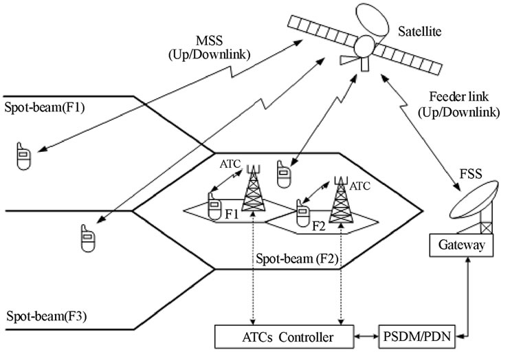
Figure 1. MSV’s hybrid system architecture.
in which α(i) is a channel gain to be estimated. Equation (2) shows a method for estimating a channel by combining the pilot symbols of the dedicated physical channel (DPCH) and CPICH. A receiver of a terminal acknowledges a pilot pattern for pilot symbols of the DPCCH in a manner similar to Equation (1).
y(j) = λ(j)α(j) + m(j) for j = 1,2,…, M (2)
in which λ(j)=(1/μ(j))1/2 refers to the power ratio of the pilot symbols of the DPCH and those of the CPICH. Equation (3) shows a method for estimating a channel by combining the pilot symbols of the DPCH, those of the CPICH, and those of the secondary common control physical channel (S-CCPCH).
z(k) = λ1(k)α(k) + l(k) for k = 1,2,…, K (3)
in which λ1(k)=(1/μ1(k))1/2 refers to the power ratio of the pilot symbols of the S-CCPCH and those of the CPICH. In Equations (1)-(3), N, M, and K are the number of pilot symbols in one slot of the CPICH, DPCH, and S-CCPCH used in estimating a channel gain, respectively. And n(i), m(j), and l(k) are presumed AWGNs that have zero means and σ2 variances, respectively. Since it is presumed that the channel gain is not changed during one slot of an estimation period, α(∙) and λ1(∙) become α and λ1, respectively. Since channelization codes used in the CPICH, the DPCH, and the S-CCPCH are different from each other, n(i), m(j), and l(k) are independent of each other. A vector of a signal received in a rake receiver of a terminal is as follows:
z’=[x(1)x(2)…x(N)y(1)y(2)…y(M)z(1)z(2)…z(L)]T
(4)where T denotes an operator of a transpose matrix. If λ, λ1, and α are known, a conditional probability density function is as follows:
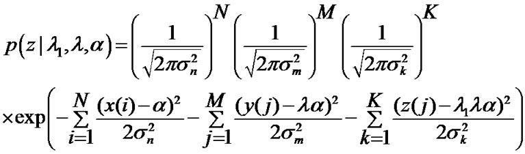
where α denotes a channel estimation value (case 1) using the CPICH, λ denotes a channel estimation value (case 2) combining the DPCH and the CPICH [5], and λ1 denotes a channel estimation value (case 3) combining the CPICH, the DPCH, and the S-CCPCH [5].
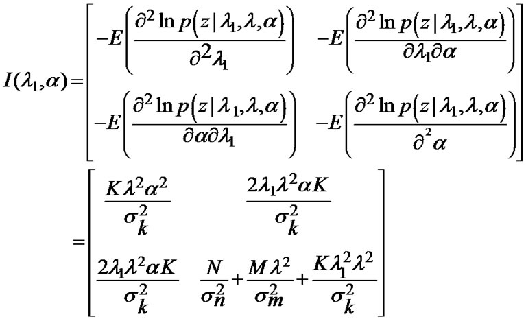
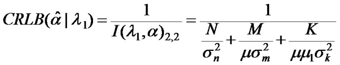
If λ1 is known, the output Cramer-Rao Lower Bound (CRLB) is that shown by Equation (7) [6].
Accordingly, comparing [7] with Equation (7) results in Equation (8), as follows.
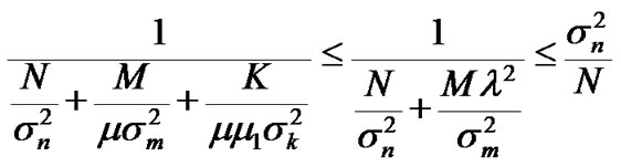 (8)
(8)
As a result, it can be seen that the channel estimation combining the CPICH, the DPCH, and the S-CCPCH is superior to both the channel estimation using only the CPICH and the channel estimation combining the CPICH and the DPCH.
3. Open-Loop Power Control
A modified OLPC and CLPC model is shown in Figure 2.
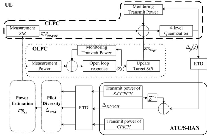
Figure 2. Modified OLPC and CLPC model.
In order to improve the accuracy of the estimation of SIR, we proposed a method to estimate the interference power, which will be presented as follows.
In Figure 3, n, k, l, Tb, and Tc denote n-th slot, k-th symbol, l-th resoluble multi-path, bit duration, and chip duration, respectively. Since the interference noise is Gaussian distributed, the variance of the interference can be found from the sum of the variances of the amplitude of the I channel and Q channel, as follows: [8]
I = E|RI|2 + E|RQ|2 (9)
Desired signal S is achieved by calculating the summation of the Sl from the 1 to L tap RAKE receiver.
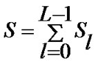 (10)
(10)
According to Friis’ free-space propagation-path-loss Formula [9], in order to apply OLPC, the average received power at the mobile station would be:
Pr= |E|2/2η0 = P0[1/(4πd/λ)]2 (11)
where P0 = PtGtGm and η0, Pt, Gt, and Gm denote intrinsic impedance of free-space, transmitted power, gain of the transmitting antenna, and gain of the receiving antenna, respectively. Path loss and shadowing effects are regarded as slow fading in this work. The general openloop response of the OLPC can be approximated as follows: [10]
O(t) = -DPin(1-exp(-t/τ)u(t) (12)
in which DPin, τ, and O(t) are the step change in mean input power, the time constant of the open-loop response, and the output, respectively.
4. Closed-Loop Power Control
CLPC is a powerful tool to mitigate near-far problems in a DS-CDMA system over Rayleigh fading channels.
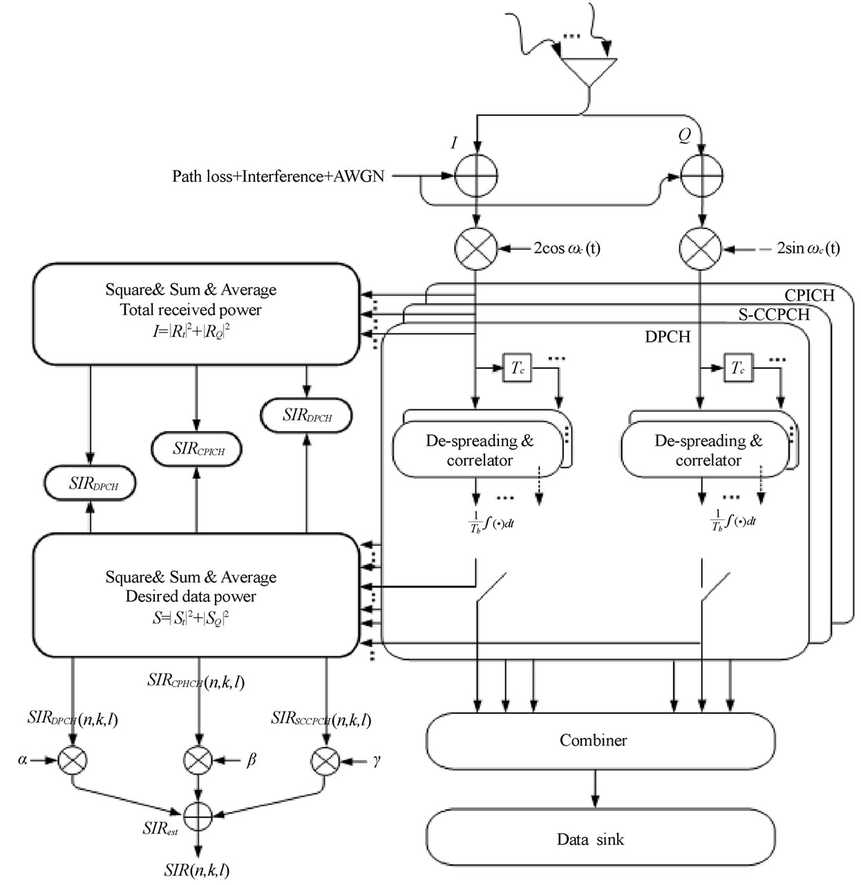
Figure 3. Block diagram of power estimation using pilot diversity.
Because of a significant difference in the RTD, there is serious performance degradation of the CLPC if the power control used for the terrestrial interface is employed as is. In order to reduce power control error, a delay compensation mechanism was selected in the ATC and satellite.
The transmitting power control (TPC) commands are generated as follows. Firstly, let us define power control error of Dε,c = SIRest - SIRtarget + Dloop delay, where Dloop delay and SIRest denote the prediction for the amount of SIR increment/decrement of the received downlink CPICH, S-CCPCH, and the estimated SIR of the received downlink DPCCH during the next time interval equal to the loop delay, respectively. Therefore, Dloop delay is added to SIRest to result in the predicted SIR value of SIRest, pred.
Dloop delay = n × Dpred (13)
where n × Dpred is the increment (or decrement) of the estimated SIR of CPICH and S-CCPCH in dB during the last frame, and n is the nearest integer to (loop delay)/ (frame length).
A four-level quantized power control step, Dp, is generated according to the region of D, as follows:
if | Dε,c | < εT and Dε,c <0, Dp(i) = DS
if | Dε,c | < εT and Dε,c >0, Dp(i) = -DS
if | Dε,c | > εT and Dε,c <0, Dp(i) = DL
if | Dε,c | > εT and Dε,c >0, Dp(i) = -DL
in which DS, DL, and εT are a small power control step, a large power control step, and the error threshold, respectively. Because of the RTD in the GEO system, the satellite radio access network (S-RAN) can reflect Dp(i) at its transmission power after about 250ms, during which time there may be a considerable change in the SIR. The S-RAN adjusts the transmitting power of the downlink DPCCH with an amount of DPCCH using the two most recently received power control steps, Dp(i) and Dp(i-1), and this can be modeled as a simple FIR filter, as follows: [11]
DDPCCH = Dp(i) - αDp(i-1) (14)
We can rewrite the above equation as follows:
DDPCCH = (1-α)Dp(i) + α(Dp(i) - Dp(i-1)) (15)
which means that DDPCCH is determined not only by Dp(i) but also by the difference between Dp(i) and Dp(i-1) with weighting factors of (1-α) and α, respectively.
5. Simulation Results
A channel with only fast fading and a channel with path loss, slow fading, and fast fading were simulated to examine the performance of the CLPC with and without an OLPC. The simulation parameters are given in Table 1. We present the simulation results of only the proposed CLPC scheme (SCHEME-II), combining the proposed OLPC and proposed CLPC (SCHEME-I), and only the proposed OLPC (SCHEME-III) over GEO satellite or ATC environments, and we compare the performance of the various conventionalOLPC and CLPC algorithms. For conventional schemes, we used the terrestrial CLPC scheme in the WCDMA system and Gunnarsson’s scheme in [12], and they are denoted in the figures as SCHEME-II with a dotted line and without SCHEME-II with a dotted line.
In our simulations, we consider a satellite system with a single beam and ignore the inter-spot interference. We assumed power control begins to work after 250$ms$ due to propagation delay.
Figures 4 and 5 show the average transmitting power consumed at the transmitters of specific users according to mobile speed. It is observed that average UE transmitted power of all schemes is dependent of mobile speed. However, we can see that users with a combination of the modified OLPC and CLPC scheme consume less power. It is also seen that at low vehicle speeds (<40
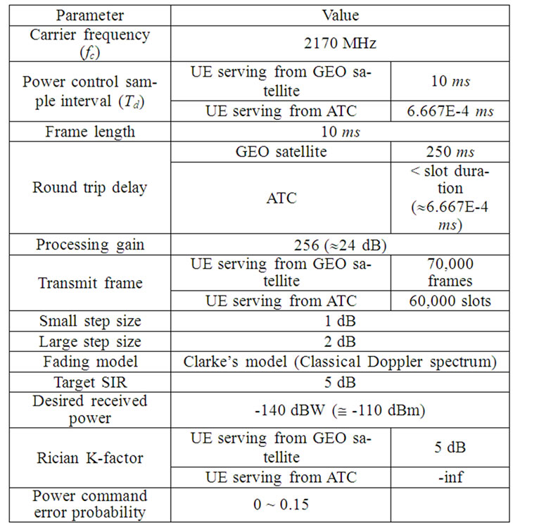
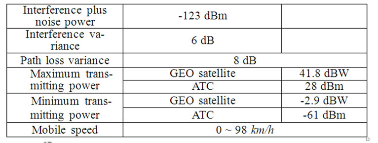
Table 1. Simulation environment.
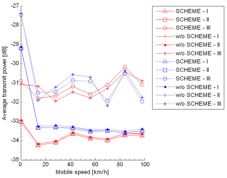
Figure 4. Average transmitting power of UE serving from ATC according to mobile velocity.
Figure 5. Average transmitting power of UE serving from GEO satellite according to mobile velocity.
km/h), combining modified OLPC and CLPC (SCHEME-I shown with a solid line) is very effective. This is because SCHEME-I compensates slow fading and path loss by monitoring transmitting power of UE and simultaneously archives diversity gain by using efficient channel estimation algorithms.
Figures 6 and 7 show the average received power consumed at the transmitters of specific users according to mobile speed. We can see that the received power of users with a combination of the modified OLPC and CLPC scheme using pilot diversity is settled compared to the other scheme. This highlights the importance of monitoring transmitting power equipment applying for a CDMA-based system. With a RAKE receiver, the dynamic range of the received power decreased as the monitoring equipment decreased.
Figures 8 and 9 show the probability density function of the received SIRs for a mobile speed of 98km/h having a probability of power control command error of 0. Intuitively, we turn out that the SCHEME-I using pilot
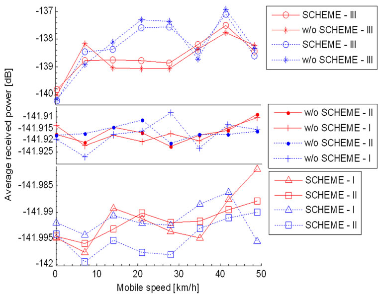
Figure 6. Average received power of UE serving from ATC according to mobile velocity.
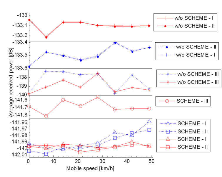
Figure 7. Average received power of UE serving from GEO satellite according to mobile velocity.
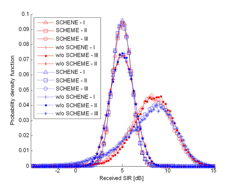
Figure 8. Probability density function of received SIRs of UE serving from ATC: K= -inf and V=98km/h.
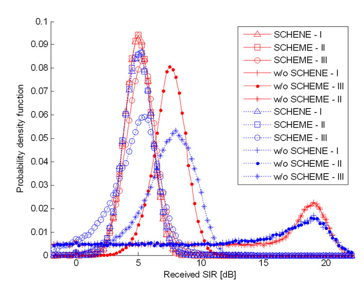
Figure 9. Probability density function of received SIRs of UE serving from GEO satellite: K=5 dB and V=98 km/h.
diversity has a larger improvement, as confirmed in the simulation results.
6. Conclusions
Conventional channel estimation methods incur many errors in the case of deep fading. In contrast, the proposed channel estimation method using the S-CCPCH to the conventional methods can obtain an improved pilot diversity gain by performing channel estimation using other channels when the first channel does not reach a required level of a received signal. Thus, it is possible to implement an ideal maximum ratio combining method in a RAKE receiver. The channel estimation method described in this paper provides a more improved performance than channel estimation in a receiver of a terminal having conventional pilot symbols of a CPICH or a DPCCH by combining pilot symbols of a CPICH, a DPCCH, and a S-CCPCH, and estimating a channel. In this paper, we have presented satellite access technologies for a future mobile system. We suggested desirable modifications for application to the 4G system. Combining modified CLPC and OLPC with delay compensation algorithms and monitoring equipment proved to provide a good performance in a MSS/ATC hybrid system. In addition, to increase the performance and to keep commonalities between terrestrial standards, more advanced transmission technologies, including multi-carrier transmission, interference cancellation, and highly efficient modulation and coding should be investigated in more detail.
7. References
[1] I. Philipopoulos, S. Panagiotarakis, and A. Yanelli-coralli, “The role of S-UMTS in future 3G markets,” ist- 2000-25030 SATIN project, SUMTS, P-specific requirement, deliverable No. 2, April 2002.
[2] G. M. Parson and R. Singh, “An ATC primer: The future of communications,” MSV, 2006.
[3] Report and order and notice of proposed rulemaking, fcc 03-15, Flexibility for Delivery of Communications by Mobile Satellite Service Providers in the 2 ghz band, the L-Band, and the 1.6/2.4 Bands, IB, Adopted: January 29, 2003, Released: February 10, 2003.
[4] S. Dutta and D. Karabinis, “Systems and methods for handover between space based and terrestrial radioterminal communications, and for monitoring terrestrially reused satellite frequencies at a radioterminal to reduce potential interference,” US Patent No. 6879829 b2, April 12, 2005.
[5] T. Luo and Y. C. Ko, “Pilot diversity channel estimation in power-controlled CDMA systems,” IEEE Transactions on Vehicular Technology, Vol. 53, No. 2, pp. 559-563, March 2004.
[6] S. M. Kay, “Fundamentals of statistical signal processing: Estimation theory,” 2nd Edition, Englewood Cliffs, NJ: Prentice-Hall, 1993.
[7] H. V. Khuong and H. Y. Kong, “BER performance of cooperative transmission for the uplink of TDD-CDMA systems,” ETRI Journal, Vol. 28, No. 1, pp. 17-30, February 2006.
[8] C. -C. Lee and R. Steele, “Closed-loop power control in CDMA systems,” IEE Proceedings of Communications, Vol. 143, No. 4, pp. 231-239, August 1996.
[9] W. C. Y. Lee, “Mobile communications engineering,” 2nd Edition, Mcgraw-Hill, 1998.
[10] S. Choe, “An analytical framework for imperfect DSCDMA closed-loop power control over flat fading,” ETRI Journal, Vol. 27, No. 6, pp. 810-813, December 2005.
[11] K. Lim, K. Choi, K. Kang, S. Kim, and H. J. Lee, “A satellite radio interface for IMT-2000,” ETRI Journal, Vol. 24, No. 6, pp. 415-428, December 2002.
[12] F. Gunnarsson, F. Gustafsson, and J. Blom, “Dynamical effects of time delays and time delay compensation in power controlled DS-CDMA,” in IEEE Journal of Selected Areas on Communications, Vol. 19, No. 1, pp. 141-151, January 2001.