Wireless Sensor Network
Vol.08 No.07(2016), Article ID:69210,8 pages
10.4236/wsn.2016.87012
Embedded UHF RFID Tag for Durability Monitoring in Concrete
Jean-Marc Laheurte1, Aladdin Kabalan1, Houssam Retima1, Eric Piedallu1, Fulvio Michelis2, Bérengère Lebental2
1ESYCOM, Université Paris-Est, UPEMLV, Marne-la-Vallée, France
2Université Paris-Est, IFSTTAR, COSYS/LISIS, Marne-la-Vallée, France

Copyright © 2016 by authors and Scientific Research Publishing Inc.
This work is licensed under the Creative Commons Attribution International License (CC BY).
http://creativecommons.org/licenses/by/4.0/


Received 2 June 2016; accepted 24 July 2016; published 28 July 2016
ABSTRACT
This paper describes the design of a battery-assisted Ultra-High Frequency (UHF) Radio-Fre- quency IDentification (RFID) tag suitable for embedding in concrete materials and its measurement in a mortar slab. The device is built to communicate wirelessly not only the ID number of the RFID chip but also the digitalized output of a strain gauge sensor. Design optimizations of the RFID antenna is based on published permittivity and conductivity values of concrete. Experimental read ranges are measured from 800 to 1000 MHz with the help of commercial test equipment. Reading is possible up to 50 cm from the surface of a mortar block for a tag embedded 5 cm below the surface. This result is the first published one for RFID tags embedded in concrete or mortar.
Keywords:
UHF RFID Technologies, Sensing RFID, UHF Tag Antennas, Concrete Monitoring

1. Introduction
Structural deficiencies in concrete structures often originate at their core from micro scale defects, whose detection is the key to predict structural ageing. For this purpose, a flexible strain gauge based on carbon nanotubes on Ethylene Tetrafluoroethylene (ETFE) was recently proposed by the authors showing highly reproducible, hysteresis-free performances [1] . However, the in-situ, real-time detection of such defects and more generally, the embedded monitoring of concrete structures remain a major technological challenge.
Recent researches demonstrated the feasibility of wirelessly powering nodes embedded in challenging environment such as soil and concrete [2] - [5] . UHF RFID is particularly appealing in this regard as embedded RFID tags can either be used in their battery-less mode or require very low energy in their battery-assisted mode. In [6] , a dedicated RFID tag design was proposed where the upper part of the antenna was not inside but at the surface of a concrete soil. The tag reading was possible up to 12.8 meters for a −15.3 dB∙m chip sensitivity but no sensing capabilities were associated to the tag. Meanwhile, chip manufacturers have developed a new generation of recently commercialized battery-assisted UHF RFID chip integrating communication and sensing capabilities [7] [8] . This paper presents the first description of the wireless communication part of a strain sensor node buried inside a concrete structure and built around one of these chips. It includes the design and fabrication issues as well as an experimental validation and a sensitivity analysis upon the variability of the concrete characteristics.
2. Description of the UHF RFID Tag
The tag shown in Figure 1 has been optimized for its embedding into mortar. It is built around the battery-as- sisted SL900A chip by AMS [8] showing a 31 μW sensitivity in its battery mode. This chip has a fully integrated temperature sensor and an interface compliant for two additional external sensors including an Analog- to-Digital Converter (ADC). The SL900A does not provide protection against DC short circuits between the antenna pads. In particular, the matching circuit included in the antenna design should not be terminated with a short circuit, but with an open one.
The tag also includes a microstrip dipole antenna and a low-power signal conditioning circuit [9] used to adjust the sensor output to the input requirements of the ADC (Figure 1). Power is supplied by a 3 V button cell battery (CR1225) offering a good compromise between size, capacity and lifetime. The use of a battery is acceptable for this application as sensor interrogation is required only weekly. The antenna, the conditioning circuit and the RFID chip are etched or soldered on the same low-cost dual-sided PCB with 35 μm thick copper metallization and FR4 dielectric (εr = 4.25, tanδ = 0.02, thickness = 1.54 mm).
The circuitry is protected by a 53 mm × 53 mm Teflon® housing (εr = 1.78, tanδ = 0.08, thickness = 3 mm) to insulate the device from the harsh concrete environment. The housing includes a 5.5 mm air layer to further improve the radiation efficiency of the antenna. The housing has an opening on its side for the passage of the wires to connect an external strain gauge exposed to concrete outside. This opening is sealed with silicone for water- proofing.
The tag can communicate with any reader using the proprietary protocol EPC Gen2 Class 3 [8] , an evolution of the EPC Gen2 protocol dedicated to UHF RFID sensor tags.
3. Antenna Design in a Mortar Block
Like mortar, concrete is a mixture of sand, cement, and water, but it also contains rock chippings or gravel which makes it much stronger and more durable than mortar. Therefore, mortar and concrete might have slightly different electrical properties depending on the aggregates type and density. Mortar is used instead of concrete in the experimental characterization because its homogeneity is controlled and its electrical characteristics are known.
For the simulations and the measurements, a (12 cm × 12 cm × 16 cm) block of mortar is considered. The upper side of the tag housing is located 5 cm below the block interface. The tag is centered with respect to the mortar

Figure 1. Assembled UHF RFID tag.
surface. To avoid the disruption that the device may cause in the concrete structure in which it is embedded, a maximum device footprint of 5 cm × 5 cm is set as the maximum diameter of the aggregates regularly used in the construction industry is typically around 5 cm [10] [11] .
To match the chip internal series impedance of (31-j320) Ω around 865 MHz [8] , a T-matching network is associated to a meandered dipole using classical design rules [12] for an optimized bandwidth over a limited surface (Figure 2). The antenna parameters are optimized in the European UHF band (865 - 868 MHz) with ANSYS HFSS 14 [13] including the Teflon box and the block of mortar. The values of all tag dimensions are summarized in the legend of Figure 2. The relative permittivity εr = 5 and conductivity σ = 0.01 S/m of mortar correspond to the properties of a dry mortar at 900 MHz extracted from the literature [14] .
4. Reading Range Formulation
The maximum Reading Range (RR) of a tag is calculated from the following formula [15] derived from the Friis equation:
 (1)
(1)
PEIRP = 3.28W is the maximum regulated effective isotropic power radiated by the reader’s antenna. Pth is the chip sensitivity (31 μW for the SL900A in its battery mode). Gtag is the gain of the tag antenna. Γ is defined as:
 (2)
(2)

Figure 2. Schematics of the tag antenna. All line widths are 5 mm except f = 1.5 mm. Line lengths: a = 0.3 mm, b = 17.15 mm, c = 2 mm, d = 3.15 mm, e = 15.15 mm, f = 3.15 mm, g = 1.98 mm, h = 1.67 mm, i = 16.65 mm, j = 1.5 mm, k = 6.35 mm, l = 5.5 mm, m = 1.6 mm, n = 2.1 mm, o = 2.9 mm, p = 2 mm, q = 18.38 mm, r = 1.72 mm, s = 2.15 mm, t = 2.5 mm, u = 0.67 mm, v = 0.98 mm, w = 2.15 mm, x = 0.5 mm, y = 43 mm, z = 26.5 mm.
where Zchip is the internal chip impedance and ZA the complex impedance of the tag antenna. In order to deliver the maximum power to the antenna, the reflection coefficient Γ has to be minimized, i.e.,  (where * indicates the complex conjugate).
In this work, the theoretical RR is estimated by using the simulated values of ZA and Gtag provided by HFSS. The experimental RR is obtained experimentally with the Tagformance UHF RFID measurement system commercialized by Voyantic [16] . Operated at a pre-set distance of 30 cm between the reader antenna and the tag, the Tagformance system measures the minimum effective isotropic power  required to wake-up and read the tag. Using Friis equation, one finds:
 (3)
(3)
The 30 cm distance is chosen so that the measurements are carried out in far field for the frequency range of interest. It is achieved using a foam cube (30 cm ×30 cm) whose electromagnetic characteristics are close to air. The experimental RR provided by the measurement system is finally obtained by combining Equation (1) and Equation (3):
 (4)
(4)
5. Sensitivity Analysis of the Reading Range upon the Variability of the Concrete Characteristics
Figure 3 and Figure 4 emphasize respectively the influence of the mortar relative permittivity (εr) and conductivity (σ) on RR. It can be used to anticipate the behavior of RR during the drying process of concrete. Indeed, εr and σ values [14] increase with the percentage of water in concrete, which decreases with time. Values such as εr = 8 and σ = 0.08 S/m correspond to the early stage of mortar with a 12% water ratio; εr = 5 and σ = 0.01 S/m correspond to an advanced stage in the drying process with a water percentage of 2.8%. RR is normalized to its maximum value (1.55 m for Figure 3 and 1.3 m for Figure 4).
As shown in Figure 3, the antenna is well tuned and sufficiently wide band to accommodate the resonance shift introduced by the change in permittivity (ε). An increased conductivity (σ) of concrete enhances losses and affects the antenna efficiency. As a consequence, RR decreases for increasing values of (σ) in Figure 4.
6. Influence of the Protective Box
In order to prove that the protective box reduces the influence of concrete and improves the performances of the

Figure 3. Normalized reading range of the antenna as a function of the frequency and the mortar relative permittivity (HFSS simulations) for a fixed conductivity σ = 0.02 S/m. The maximum RR is 1.55 m, obtained at 860 MHz for εr = 8.
antenna, the reference tag is simulated within a protective box featuring no air layer between antenna and box, and its performances are compared with those of the reference geometry. In Figure 5, the relative shift of resonant frequency with respect to the reference tag is given as a function of mortar permittivity for a fixed mortar conductivity σ = 0.01 S/m. The resonant frequency of the antenna protected by the thinner box is much more sensitive to the changes in mortar permittivity.
In Figure 5, the relative decrease of RR with respect to the reference tag is also given as a function of mortar conductivity for a fixed mortar permittivity εr = 5. In the absence of air layer, RR decreases more rapidly when the mortar conductivity is increased, which confirms that the air layer around the antenna is highly beneficial for improving the radiation efficiency of the antenna. However, one can observe that this effect is attenuated when the conductivity reaches value such as σ ≤ 0.01 S/m, i.e. at low water percentage when the mortar is fully dried.
7. Evaluation of the Experimental Reading Range
RR measurements are performed between 800 and 1000 MHz using the UHF RFID measurement system [16] and the test bench described in Figure 6. The device is first evaluated in air without and with housing. Then, the device is placed in a 2-litre mould of mortar. Measurements are carried out three days after casting the mortar, so that it is expected to be fully hydrated. The maximum RR = 270 cm occurs at 934 MHz in air without housing (Figure 7). With housing, the maximum RR = 240 cm is shifted to 897 MHz. The 140 cm RR in the European band shows that the tag in its housing can still operate in free space even though it has been designed to operate in concrete.
The experimental Q-factor and the experimental RR are significantly lowered in mortar as indicated by the smooth variation of the RR response. Within mortar, the maximum RR drops to 55 cm at 915 MHz and 50 cm at 865 MHz. It is likely that the variation of water content and drying conditions from one type of mortar to another and from one preparation method to another alter the maximum RR which was expected to reach 95 cm in HFSS simulations for the European UHF band. Also, the conditioning circuit was roughly modeled by metallic pads in HFSS simulations. Therefore, its coupling with the antenna and its influence on ZA was probably underestimated
8. Conclusions
This paper described a UHF RFID tag embedded in mortar, which was the first published prototype built around a battery-assisted chip integrating sensing capabilities. A protective case sheltered the device from the aggressive environment in concrete. The overall tag size is comparable with the volume of the largest aggregates used in concrete industry.
The price of miniaturization is the decrease of antenna bandwidth of the antenna, but according to the HFSS

Figure 4. Normalized reading range as a function of the frequency and the mortar conductivity (HFSS simulations) for a fixed relative permittivity εr = 5. The maximum RR is 1.3 m, obtained at 870 MHz for σ = 0.02 S/m.
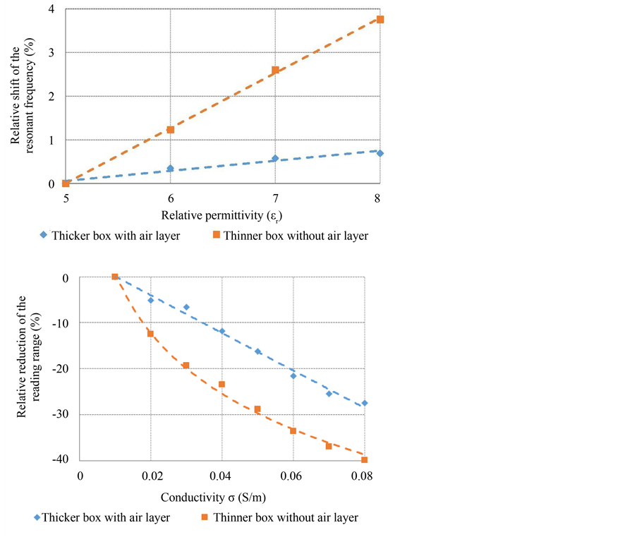
Figure 5. Relative downshift of the resonance frequency (upper) and relative reduction of the reading range (bottom) with increasing relative permittivity for a device with or without air layer between the antenna and the Teflon® box. The shift is expressed with respect to the resonance frequency (upper) and reading range (bottom) of the reference geometry with or without air layer for the lowest conductivity σ = 0.01 S/m and dielectric permittivity εr = 5.

Figure 6. Test bench including the Tagformance measurement system. Tag housing centered in the (12 cm × 12 cm × 16 cm) block of mortar, 5 cm below its surface.

Figure 7. Experimental read range as a function of frequency for the UHF tag in air with and without housing and embedded in the mortar block.
simulations, the RR bandwidth is sufficient to accommodate some variability in the concrete characteristics. The sensitivity of the tag to concrete variability was strongly reduced by implementing a 5mm-thin air layer between the protective casing and the antenna.
The performances of the device were evaluated experimentally for a 5 cm burying depth in a mortar block. The reading distance reached up to 50 cm while the final volume of the assembled device was more than 3 times smaller than the state of the art embedded wireless nodes for concrete [17] . A 50 cm reading distance is sufficient to enable the monitoring of a concrete structure with a handheld RFID reader, especially for the transfer of strain gauge data.
The reading distance could be further improved following two approaches: firstly a more accurate evaluation of the conductivity and permittivity of the concrete to be monitored, secondly a better decoupling between the conditioning electronics and the antenna.
Cite this paper
Jean-Marc Laheurte,Aladdin Kabalan,Houssam Retima,Eric Piedallu,Fulvio Michelis,Bérengère Lebental, (2016) Embedded UHF RFID Tag for Durability Monitoring in Concrete. Wireless Sensor Network,08,137-144. doi: 10.4236/wsn.2016.87012
References
- 1. Michelis, F., Bodelot, L., Bonnassieux, Y. and Lebental, B. (2015) Highly Reproducible, Hysteresis-Free, Flexible Strain Sensors by Inkjet Printing of Carbon Nanotubes. Carbon, 95, 1020-1026.
http://dx.doi.org/10.1016/j.carbon.2015.08.103 - 2. Jiang, S. (2011) Optimum Wireless Power Transmission for Sensors Embedded in Concrete. Florida International University, University Park.
- 3. Shams, K. and Ali, M. (2007) Wireless Power Transmission to a Buried Sensor in Concrete. IEEE Sensors Journal, 7, 1573-1577.
http://dx.doi.org/10.1109/JSEN.2007.908230 - 4. Ishida, H. and Furukawa, H. (2015) Wireless Power Transmission through Concrete Using Circuits Resonating at Utility Frequency of 60 Hz. IEEE Transactions on Power Electronics, 30, 1220-1229.
http://dx.doi.org/10.1109/TPEL.2014.2322876 - 5. Jonah, O. and Georgakopoulos, S.V. (2013) Wireless Power Transfer in Concrete via Strongly Coupled Magnetic Resonance. IEEE Transactions on Antennas and Propagation, 61, 1378-1384.
http://dx.doi.org/10.1109/TAP.2012.2227924 - 6. Jeong, S.H. and Son, H.W. (2011) UHF RFID Tag Antenna for Embedded Use in a Concrete Floor. IEEE Antennas and Wireless Propagation Papers, 10, 1158-1161.
http://dx.doi.org/10.1109/LAWP.2011.2172179 - 7. EM Microelectronic (2012) EM4325 Datasheet [Online].
http://www.emmicroelectronic.com/ - 8. AMS (2013) SL900A Datasheet [Online].
http://ams.com/eng - 9. Michelis, F., et al. (2014) Wireless Flexible Strain Sensor Based on Carbon Nanotube Piezoresistive Networks for Embedded Measurement of Strain in Concrete. EWSHM, 7th European Workshop on Structural Health Monitoring, Nantes, 8-11 July 2014, 1780-1787.
https://hal.inria.fr/hal-01022026/document - 10. America’s Cement Manufacturers (2015) Aggregates.
http://www.cement.org/cement-concrete-basics/concrete-materials/aggregates - 11. (2015) Aggregates for Concrete. University of California, Berkeley.
- 12. Laheurte, J.-M. (2014) UHF RFID Tags: Design and Technologies. John Wiley & Sons, Inc., Hoboken, 84-85.
- 13. [Online].
http://www.ansys.com/Products/ - 14. Soutsos, M., Bungey, J., Millard, S., Shaw, M.R. and Patterson, A. (2001) Dielectric Properties of Concrete and Their Influence on Radar Testing. NDT & E International, 34, 419-425.
http://dx.doi.org/10.1016/S0963-8695(01)00009-3 - 15. Nikitin, P.V., Rao, K.V.S., Lam, S.F., Pillai, V., Martinez, R. and Heinrich, H. (2005) Power Reflection Coefficient Analysis for Complex Impedances in RFID Tag Design. IEEE Transactions on Microwave Theory and Techniques, 53, 2721-2724.
http://dx.doi.org/10.1109/TMTT.2005.854191 - 16. Voyantic Ltd. Kutojantie 11, FI-02630 Espoo, Finland.
- 17. Chang, C.-Y. and Hung, S.-S. (2012) Implementing RFIC and Sensor Technology to Measure Temperature and Humidity inside Concrete Structures. Construction and Building Materials, 26, 628-637.
http://dx.doi.org/10.1016/j.conbuildmat.2011.06.066