Wireless Sensor Network
Vol.4 No.4(2012), Article ID:18620,6 pages DOI:10.4236/wsn.2012.44014
A Wireless Sensor Network Ad-Hoc Designed as Anti-Theft Alarm System for Photovoltaic Panels
Dipartimento di Elettronica e Telecomunicazioni, Politecnico di Torino corso Duca degli Abruzzi, Torino, Italy
Email: {silvano.bertoldo, oscar.rorato}@polito.it
Received January 15, 2012; revised February 27, 2012; accepted March 14, 2012
Keywords: WSN; Alarm System; Photovoltaic System; Electronic Board; Ad-Hoc Designed Board; Low Cost; Ad-Hoc Protocol
ABSTRACT
Photovoltaic (PV) systems have attracted increasing attention in last years as well as Wireless Sensor Networks (WSNs), which have been used in many application fields. In PV plants, especially in ground installations, a lot of thefts and damages occur due to the still high cost of the modules. A new experimental WSN ad-hoc has been designed to be an anti-theft alarm system. Each node of the network is directly installed under each PV string and it is equipped with an accelerometer sensor capable to detect a minimum displacement of the panel from its steady position. The WSN presents a star topology: a master node cyclically interrogates the slave nodes through RF link. It collects all the nodes responses and communicates though a RS-232 interface with a control PC checking the network status. When a slave node detects an alarm, continuous messages are sent to the control PC which turns on all the alarm signaling systems. The control PC is equipped with an open source operative system and software and provides for SMS, e-mail and sound-light signaling in case of alarm. It also communicates with a remote server where all the WSN information is stored. A first low cost experimental WSN has been already installed and it is working properly.
1. Introduction
Wireless Sensor Networks (WSNs) have attracted an increasing attention in recent years because of the large number of potential applications. They are used for collecting, storing and sharing data, for monitoring application, surveillance purposes and much more. The focus on communication issues, network protocols and the always smallest size of the electronic boards enabled more applications to be deployed. The catalog of available WSN platforms increased to include many types of radio and processor features in order to be employed in a huge number of fields [1]. A good description of the actual landscape of WSN and future trends can be found in an article written by R. Das in September 2011 [2].
The researches about alternative energy sources together with many government incentives have caused a substantial increase in the number of photovoltaic (PV) system installations. However stealing and damages to PV modules are increasing too.
For instance, in the solar power plant located in Serre Persano, in the province of Salerno, Italy, 7000 of 60,000 installed panels have been stolen in less than one year [3]; an online newspaper reported that the theft of 140 panels during the New Year’s Eve 2012 caused an economic damage of 150,000 EUR [4].
A new low cost experimental and prototypal Wireless Sensor Network (WSN) has been ad-hoc designed and tested to increase the PV protection implementing an adhoc communication protocol.
No already existent communication protocol has been used but a new one has been studied and implemented in order to completely design all the aspects of the system.
In the next paragraphs all aspects of the experimental WSN will be described.
2. WSN General Description
Accelerometers have been used in order to detect an alarm when a PV panel is removed from his installation point.
An electronic board equipped with such an accelerometer sensor has been designed to be installed below each PV string to detect movements and transmit to a central node the consequent alarm signal.
The entire WSN has been designed with a masterslave architecture and star topology. A central node, called master node or Access Point (AP), performs periodic monitoring and scanning operations of all the sensors and dialogues with an embedded control PC. It has to be noted that each slave nodes communicates only with the master node and not between each other. The control PC is a common commercial embedded PC connected to internet using a GPRS router, thus allowing the communication with a remote server and remote management operations.
Each slave node has an almost irrelevant current consumption and is fed up by an appropriate power network. This one, together with RS-232 serial cable that connects the master node with the embedded control PC are the only two wiring rows required by the WSN.
Each board comprises a solid state triaxial accelerometer connected to a microcontroller which can process data and potentially detect the alarms. The microcontroller generates messages and transmits through RF link to the master node using a proprietary protocol. The same AP communicates with the embedded PC control via RS-232 serial interface.
The AP performs a cyclical interrogation to each slave node of the WSN in order to monitor the network status. Such information are processed by the control PC and then sent to a remote server to be stored. When a sensor detects an alarm, a continuous signal is sent to the AP and, consequently, to the control PC which turn on all the alarm signaling systems: SMS and/or e-mails are sent to a list of previously configured users, and a sound-light signaling system is activated.
The management of alarms generated by a sudden movement is made directly by the microcontroller. The acceleration values measured by each sensor on the three axes in terms of voltages, are sampled and converted to acceleration (in terms of g value). The algorithm operates directly on these acceleration values and triggers an alarm when a 5 degrees tilt variation is detected in at least one of the three directions.
To make the system more robust a tool of automatic restart for the electronic board in case of “lock” of the microcontroller has been included in the board firmware.
3. Ad-Hoc Designed Hardware
The WSN is made up by several slave nodes and a single master node. All the electronics boards are entirely designed specifically for this application (Figure 1).
The electronic boards have been designed to perform both the sensor node functions and the access point functions by varying only the firmware. This choice greatly shortens development time and maintenance costs: a possible component fault could be the same for each node of the WSN.
All the boards power supply is equal to ±12 V provided by a specific power network. On the +12 V line the current consumption is approximately 50 mA in normal operative conditions and about 200 mA when the RF transmission is on. On the –12 V line the current consumption is negligible. As each sensor board perform the RF transmission individually (thanks to the developed communication protocol between AP and slave nodes, see details in paragraph 4 and lasts a very short time interval, it can be said that the average current consumption of each board is slightly greater than 50 mA.
A single board is made up by several subsystems [5] such as:
• Power supply stages;
• RAM memory;
• Sensors (with accelerometers)/Filters and Analog to Digital conversion chain;
• Microcontroller;
• RF radio circuits;
• RS-232 transceiver.
In the next sub-paragraphs each one of the above sections will be described with particular attention to the choice made during the sensor board design.
3.1. Power Voltage Stage
Power voltage stage provides for different power values needed by the electronic components. In particular using an integrate switching controller (Texas Instrument TPS54357) a +5 V d.c. power supply is derived as needed by the ADC, while using two linear power regulators (Texas Instrument TPS73733 and Texas Instrument TPS73730) +3 V d.c. and +3.3 V d.c. values are derived as needed by microcontroller, other integrated components and accelerometers sensors.
3.2. SRAM Memory
Each board is equipped with a SRAM memory of 512 kb. Its purpose should be to store the data acquired by the accelerometer in order to have at our disposal a sufficient
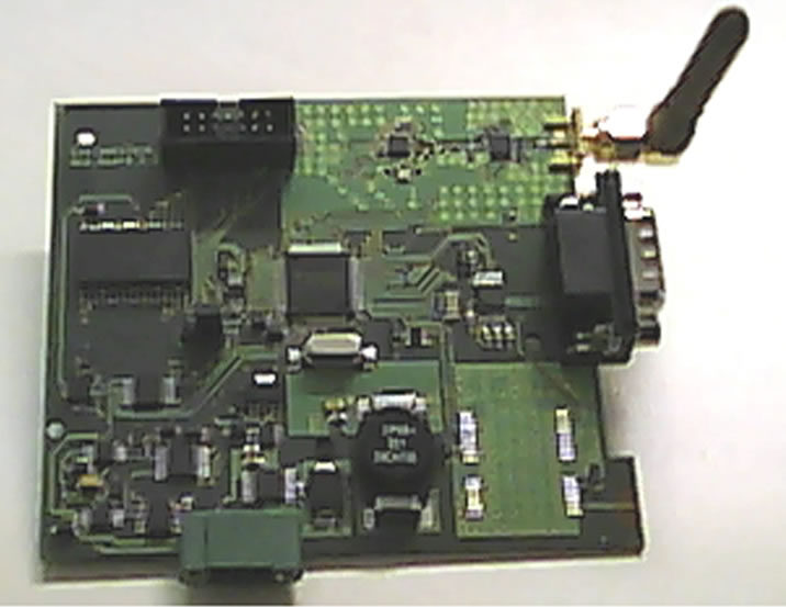
Figure 1. Sensor board used in the WSN.
time window for data processing. Memory access is performed with an 8-bit parallel data bus and a 19-bit parallel address bus both driven by the microcontroller. At the moment the SRAM memory is not used and it has been included on board to be used in the next firmware and WSN versions.
3.3. Sensors
The card is provided with two types of sensors: a solid state analog accelerometer (Analog Devices ADXL327) and a digital temperature sensor (Texas Instruments TMP121).
The temperature sensor is needed to compensate for the drift of the accelerometer due to the external temperature variations. The chosen sensor is fully digital and information on temperature are obtained by periodic queries performed by the microcontroller through the SPI bus.
The accelerometer sensor is an analog sensor built with MEMS technology; it has three voltage outputs, one for each axis, corresponding to values between –2 g and +2 g. Each output has to be connected to a specific circuit to force the usable bandwidth of the accelerometer [5]: for this application a 220 nF capacitor has been used in order to operate with a bandwidth of approximately 22.6 Hz, sufficient for detecting movements of human origin.
Accelerometer outputs are sent to a 3-ways multiplexer which allow to convert digital values with an ADC. Analog to digital conversion is driven by the microcontroller via SPI bus at regular intervals. The system performance allow to estimate the acceleration of each axis with a resolution of 3 mg, almost equal to the one measured with a seismograph.
3.4. Microcontroller
The microcontroller (Texas Instruments MSP430F2619) manage all the other chips installed on the board. It also process the data collected by the sensors in real time in order to send a potential alarm communication. The choice of this type of microcontroller was driven by its low power consumption: when it is used in active mode its current consumption is equal to approximately 8 mA [7].
The firmware is downloaded to the microcontroller through the TI programmer using the JTAG protocol.
3.5. RF Circuits
The RF circuits are the part of the board which allows the sensors to communicate with the access point in a bidirectional way.
The RF circuits are made up by a transceiver (Texas Instruments CC2500) and an amplifier (Texas Instruments CC2591) used in a dual manner: power amplifier in transmission and low noise amplifier in reception. A matching network has been designed between the transceiver and the amplifier in order to allow the maximum power transfer between the modules and to avoid the transmission of spurious frequency components. As the other components, the transceivers is also driven by the microcontroller though the SPI bus.
The chosen operating frequency for the WSN is 2.4 GHz in order to deal with small antennas. Data packets are transmitted with a FSK modulation and a baud-rate equal to 9600 bps.
3.6. RS-232 Transceiver
The communication between the master node and the embedded PC is performed through the RS-232 standard. Since the voltage levels of the RS-232 protocol are not compatible with the voltage levels of the microcontroller a level shifter is used, in order to enable the dialogue between the microcontroller of the master node and the embedded PC.
As the distance between the control PC and the AP could be more than 100 meters, a baud-rate equal to 1200 bps has been chosen accordingly to Texas Instruments specification [8]. Moreover to increase the robustness of the communication and external noise immunity a category-6 UTP cable has been chosen, since sensors will be installed outdoor.
4. Ad-Hoc Communication Protocol
As the wireless communication between nodes is based on packets exchange it is necessary to describe the packets structure before explaining the ad-hoc communication protocol.
For toughness reasons a single packet type has been used in the network protocol. The packet structure is reported in Table 1 with the size of each field.
The field Rec. Address contains the recipient address while the field Sender Address contains the information about the board which sends the packet. CRC1 and CRC2 are two fields automatically inserted by the radio transceiver in order to improve the communication performances: they allow to detect transmission errors which might always occur.
Three different values can be contained inside the field Status Byte and identify the type of a certain packet:
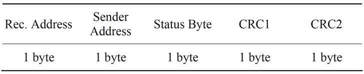
Table 1. WSN packet structure.
• “R” value: it stands for a status request packet;
• “O” value: it stands for an acknowledgment (ACK) packet;
• “A” value: it stands for an alarm packet.
The master node queries each slave node every 8 seconds and send the received information to the embedded PC via serial interface. The transmission of a single packet between the AP and a slave node lasts about 8.3 ms, a negligible time compared to the time interval needed to complete an interrogation to a board.
A protocol transaction starts with a R packet sent by the AP. The interrogated slave node must answer within a timeout limit of 10 seconds. If within that time no response is received by the AP, no string is sent to the embedded PC where the serial data processing software (see paragraph 6 for details) will detect a possible alarm warning. If AP receives an O packet coming from the interrogated slave node it continues to query the other WSN boards until a complete interrogation cycle is performed (Figure 2). At the end of each complete cycle a special string, containing the message “AP_ONLINE” is then sent to the control PC by the AP in order to report the regular WSN working.
If one of the slave nodes detects an alarm, an A packet is sent immediately to the AP which interrupts the normal interrogation cycle and forward the alarm information to the control PC. The A packets are continuously sent by the node until a restart operation of the entire WSN is performed (Figure 3).
5. Alarm Detection Procedure
As already told in paragraph 1, a possible alarm event is triggered when a 5 degrees tilt variation is detected by a sensor board in at least one of the three coordinate directions. The alarm detection is performed directly by the firmware on each slave node. It has to be noted that the firmware for the slave nodes (exactly as well as the one for the AP) has been entirely developed ad-hoc for this WSN.
The slave nodes firmware has been developed to monitor PV panels position. As soon as the WSN is turned on each node acquires data from the three axis accelerometer for 30 seconds in order to establish with sufficient precision the operating position of the panel. At the end of this “learning phase” the proper processing of the accelerometer signals starts, in order to reveal potential alarms.
During the WSN normal working the accelerometer sampling frequency is equal to 100 Hz so it possible to immediately detect an alarm when a panel is moved from its steady position. To avoid false alarms due to accidental movements (e.g. vibrations due to the transit of heavy vehicles near the PV system) a time variant median filter
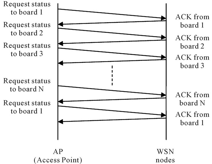
Figure 2. Example of a protocol transaction without alarm detection.
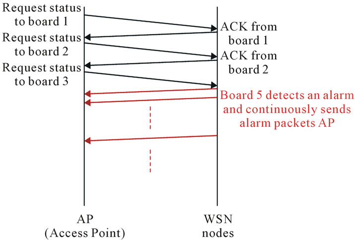
Figure 3. Example of a protocol transaction when a board detects an alarm.
has also been implemented.
The alarms detection is made by comparison between the values acquired by the accelerometer during the “learning phase” and the filtered instantaneous values. If the difference is greater than a well defined threshold (which corresponds to a 5 degree displacement) an alarm is detected and the A packet is immediately sent to the AP.
6. Processing Software on the Control PC
The processing software runs on the embedded control PC which is equipped with a Linux Operative System (Debian 6.0 distribution) in order to reduce the WSN costs.
The software analyzes the data coming from the serial port of the PC where the WSN master node is connected.
The processing software is structured into two phases: “learning” and “running”. Learning operations are performed at each software start up and allow to learn the status of all the WSN boards when the power is turned on. The running phase works on the basis of information acquired during the learning phase and runs until the PC is shut down or an alarm event is triggered. It records all the WSN information in some appropriate log files and once a day transfers them to the remote server to keep an historical archive of network behaviors.
In case of alarm detection, the software immediately activates the communication with the remote server, sends the emails to a list of preconfigured addresses, turns on the relay for the sound-light signaling device, and connects to a dedicated FTP server which provide for a service that sends SMS messages. Each WSN monitoring operation in progress is stopped in order to perform a sudden communication of the alarm.
Four distinct alarm events can be triggered by the software on the control PC:
1) Receipt of an A packet. It means that a sensor sends a packet which contains an alarm detection corresponding to a possible movement of a PV panel from its steady position (see Section 5).
2) Receipt of wrong strings on the serial port. It means that the communication between master node, embedded PC and slave nodes is compromised. Some possible reasons could be board damages or even intentional jamming.
3) Lack of packets reception coming from a certain slave node. It means that such sensor was disconnected from the power supply or has been damaged.
4) Expiration of the serial port timeout; the software listens to serial port and if it does not receive data within a certain time interval (defined in the software settings) an alarm event is triggered. That is because the lack of data reception may be due to an intentional interruption of the serial cable.
Since it is necessary that the WSN is connected to internet with a GPRS modem to transfer file between control PC and remote server, to send e-mail and to connect to the FTP server for SMS, and to perform management operations, it is important to monitor the internet connectivity. This operation is executed by a script running on the server, which periodically ping the GPRS modem. If the WSN does not appear online for more than 2 consecutive interrogations a further alarm event is triggered by the remote server. In this case no soundlight communication is turned on but only email and SMS are sent.
7. Sensors Calibration
The alarm detection is made through the identification of a tilt variation of the panel strictly greater than 5 degrees on at least one of the three axes from its steady position. Sensors sensitivity and offset values are needed to evaluate the right acceleration values and the corresponding position. Datasheets report such nominal values but they are subject to slight variations within a tolerance interval. Hence to establish a correspondence between the accelerometers values (expressed in g acceleration) and the corresponding angular variation, an offline calibration procedure was performed.
Before calibrating all the sensors used in the WSN a particular firmware has been written to acquire data from the sensor boards without transmit any packet to the master node. The board is then forced to transmit all the acceleration measured values directly to a specific PC of the laboratory, used only for calibration (it has to be noted that only for debug and test purposes all the boards have been equipped with RS-232 interface, exactly as well as the master node which use such connection also to communicate with the control PC).
Two calibration algorithms have been investigated and implemented: the first proposed by P. Lukowicz et al. [9] and the second by I. Frosio et al. [10]. Both algorithms give as output the offset and the sensitivity of a MEMS accelerometer sensor in each of the three directions. These values have been used to compute the angular position of a board in term tilt value.
A test board has been used to establish which one was the most useful for the sensors employed in the WSN. A large number of measures have been made for each algorithm and the results are reported in Table 2 and Table 3.
Lukowicz algorithm shows that the board is able to measure a tilt with less than 3 degrees accuracy, while using the Frosio one the accuracy for tilt measurement is less than 1.5 degrees. Hence the second algorithm has been chosen.
Each sensor board has been calibrated in the laboratory workbench before its installation in the anti-theft
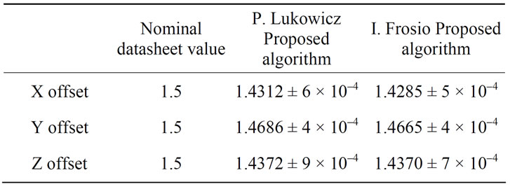
Table 2. Calibration procedure results for a test board: offset values.
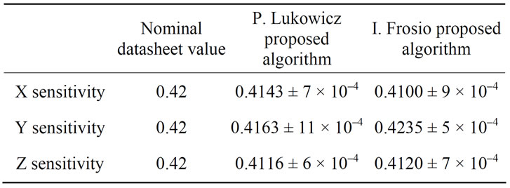
Table 3. Calibration procedure results for a test board: sensitivity values.
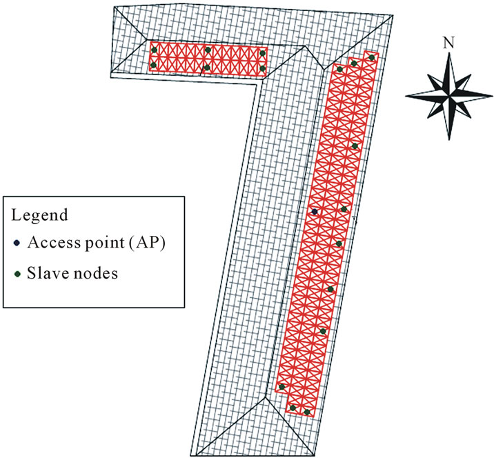
Figure 4. Plant of the first experimental WSN installed.
alarm system.
8. Conclusions and Outlooks
This paper present a Wireless Sensor Network ad-hoc designed as anti-theft alarm system for photovoltaic panels.
All the hardware, the firmware and the software is ad-hoc designed and developed for this purposes paying particular attention to the overall cost reduction.
The first experimental WSN has been installed in December 2011 and it’s running. As shown in Figure 4 it is made by 17 sensor boards and 1 master node.
Next steps will concern: a more massive stress test period in order to identify the false alarm causes; a new firmware development in order to improve the alarm detection and to make use of the other integrated circuits already present on the boards and not yet used at the moment. It would be also possible to use some already existent protocols such as, for example, ZigBee, in order to improve the communication performances.
The sensors employed in this WSN are prototypes. Appropriately reducing the board size, in the future, they can be directly integrated inside the PV panels.
9. Acknowledgements
The present work has been produced as a result of an experimental activity promoted by the RSG (Remote Sensing Group, www.remotesensinggroup.polito.it) of DET (Department of Electronic and Telecommunications. www.det.polito.it), Polytechnic of Turin, a local operative unit of CINFAI (Consorzio Interuniversitario Nazionale per la Fisica delle Atmosfere e delle Idrosfere, www.cinfai.it), and it is developed in collaboration with Envisens Technologies s.r.l. (www.envisens.com), spinoff of Polytechnic of Turin.
The PCBs have been provided by Cad Line s.r.l. (www. cadlinepcb.it).
REFERENCES
- V. Galluzzi and T. Herman, “Survey: Discovery in Wireless Sensor Networks,” International Journal of Distributed Sensor Networks, 2012, Article ID: 271860. doi:10.1155/2012/271860.
- R. Das, “Wireless Sensor Networks: the challenges and opportunities,” 2011. http://www.mpdigest.com/issue/Articles/2011/sept/idtech/Default.asp
- V. Gualerzi, “Ora il solare fa gola anche ai ladri, rubati all’ENEL migliaia di pannelli,” 2007. http://www.repubblica.it/2006/11/sezioni/ambiente/solare/furti-pannelli/furti-pannelli.html
- Maxi furto di pannelli fotovoltaici, “Bottino da 150 mila euro,” 2012. http://www.arezzoweb.it/notizie/speciale.asp?idnotizia=72527
- O. Rorato, “Studio e progettazione di sistemi elettronici per monitoraggio ambientale,” Politecnico di Torino, Torino, 2012.
- Small, Low Power, “3 Axis ± 2 g Accelerometer ADXL- 327, Analog Devices,” 2009. http://www.analog.com
- Texas Instruments, data sheet, “Mixed Signal Microcontroller MSP430F261x MSP430F241x,” 2011. http://www.ti.com/
- RS232 Specifications and standards, 2010. http://www.lammertbies.nl/comm/info/RS-232_specs.html
- P. Lukowicz, H. Junker and G. Troester, “Automatic calibration of body worn acceleration sensors,” Pervasive Computing, Vol. 3001, 2004, pp. 176-181. doi:10.1007/978-3-540-24646-6_11
- I. Frosio, F. Pedersini and N. A. Borghese, “Autocalibration of MEMS Accelerometers,” IEEE Transaction on instrumentation and measurement, Vol. 58, No. 6, 2009, pp. 2034-2041. doi:10.1109/TIM.2008.2006137.