Journal of Biomedical Science and Engineering
Vol.5 No.11(2012), Article ID:24672,5 pages DOI:10.4236/jbise.2012.511077
Study of various molar crown designs and their assessment
![]()
Department of Mechanical Engineering, Visvesvaraya National Institute of Technology (VNIT), Nagpur, India
Email: rashmiu71@rediffmail.com
Received 14 February 2012; revised 17 August 2012; accepted 10 September 2012
Keywords: Dental Crown; Thresholding; Boolean Operation; Segmentation
ABSTRACT
Dental crowns are best utilized as a way to improve the cosmetics of a tooth appearance when the crown simultaneously serves other purposes also, such as restoring a tooth to its original shape or strengthening a tooth. The study presents four different designs of molar crown depending upon the tooth loss. The finite element results obtained suggests that restored material which fills the treated cavity along with small portion of root canal can help in retaining the restored tooth and can allow larger deformations for stresses induced well within the limit.
1. INTRODUCTION
Crowns are tooth-shaped “cap” that are placed over a tooth to restore its shape and size, strength, appearance or cover a dental implant. The strengthening capability of dental crowns is related to the fact that they cup over and encase the tooth on which they are placed, thus serving as a splint which binds the tooth together. The geometry of the crown is selected and decided based on various factors like type of tooth, amount of tooth loss, location of tooth and finally the skill of dentist. The performance of restored tooth should be ideally observed for the certain period of time. Based on the stress distribution pattern, best design should be selected to increase the success rate.
The objective of the study is to carry out the stress analysis of different designs of molar crown depending upon the tooth decay and suggest optimal design for the success of restoration treatment. Further, the study suggests that simulating the behaviour of the tooth for a particular restoration gives sufficient evidence of failure location as well as approximate stress distribution pattern beforehand. For carrying out the stress analysis, the molar tooth is accurately modelled and appropriate material properties are assigned to different layers of the restoration. The following section presents the details about modelling of natural tooth and restored tooth.
2. MODELLING OF NATURAL TOOTH
CT scan of the human mandibular left second molar tooth is obtained. The CT scanned images are imported in MIMICS software which converts CT data to 3 D model. For distinguishing the different layers of natural tooth, thresholding [1] is carried out. Thresholding facilitates the segmentation of objects. Segmented object will contain only those pixels of the image with a value higher than or equal to the threshold value. Sometimes an upper and lower threshold is needed. The segmentation mask contains all pixels between these two values. A low threshold value makes it possible to select the soft tissue of the scanned patient. With a high threshold, only the dense parts remain selected.
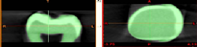
A segmentation mask is a collection of pixels of interest that constitute an object. One can create several dependent or independent masks, each displayed with their own identifying color. Usually several masks will be needed to obtain a final segmentation object that contains the required information. The Figure 1 shows processing of CT data, different views of the tooth and generation of 3D model of tooth.
The 3D model thus obtained is meshed to make it optimal for FEA (finite element analysis) purpose in MIMCS itself. Further, re-meshing reduces the amount of triangles of the object and improves the quality of the triangles by removing extra shells. After obtaining a surface mesh it can be imported in ANSYS and a volumetric mesh is created from this surface mesh in ANSYS environment.
3. MODELING OF MOLAR CROWN
The natural tooth is initially constructed as a solid model with single material in ANSYS Environment. The carries formation leads to decay of tooth. If decay is small and restricted to the enamel layer only, part of the enamel is drilled and removed. The cavity so created is filled by artificial material like ceramic, silver amalgam, resin composite, cast gold etc. Depending upon the shape of cavity four different molar crowns are designed.
 (a)
(a)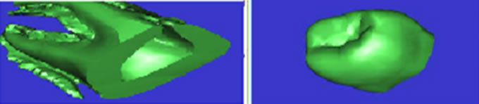 (b)
(b)
Figure 1. Different views of tooth in MIMICS software. (a) shows the sectional front view of the molar tooth; (b) shows the top view of the tooth. The CT scan image is obtained in the form of number of slices stacked one over other. The solid model of the tooth prepared in MIMICS software is split in two parts to show that it is hollow; (c) shows the lower part of the tooth which is housed in the bone; (d) shows the upper part of the molar tooth showing the crown.
3.1. Modeling of Molar Crown Design-1
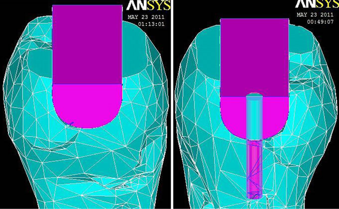
The design-l in dental terminology [2] is known as MOD (Mesial Occlusal Distal) which indicates that the cavity created start from mesial region and along the occlusal surface ranges up to the distal region. The modelling is done using the following procedure. The spline through key points is plotted by entering the three dimensional coordinates of the cavity. The straight line is used to convert spline into closed boundary area. The closed boundary area is extruded along normal direction. This procedure is used for solid cavity as a single entity. The solid cavity is subtracted from natural tooth volume by Boolean subtract command. Design-l of molar crown is as shown in Figure 2(a).
3.2. Modeling of Molar Crown Design-2
If the decay of the tooth further worsens it affects the pulp region also. Here, besides the enamel and dentin, a cavity is created in the root of the tooth also. This is done to remove the affected pulp and surrounding nerves and blood vessels which leads to pain. This cavity is called MOD root canal cavity. Again for modelling of tooth, the molar tooth model is imported in ANSYS from MIMICS. The MOD preparation procedure remains the same. The cavity is prepared by creating a projected cylinder. The root canal cavity is subtracted from natural tooth volume by Boolean operation. Design-2 of molar crown is as shown in Figure 2(b).
3.3. Modeling of Molar Crown Design-3
The design-3 is created for the tooth which is decayed on the occlusal surface toward the mesial region only. The
 (a)
(a)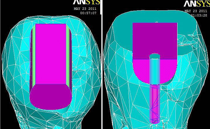 (b)
(b)
Figure 2. Different designs of molar Crown: (a) the design-1 indicates mesial-distal-occlusal cavity; (b) the design-2 indicates mesial distal occlusal with root canal cavity; (c) shows the mesial occlusal cavity termed as design-3; and (d) shows the Endo mesial occlusal with root canal cavity.
part of the enamel towards distal region is kept intact. The procedure of modelling of MO (Mesial Occlusal) design is as follows. The closed boundary area is extruded along normal direction 2 mm away from distal region. This procedure is used for modelling the solid cavity as a single entity. The solid cavity is subtracted from natural tooth by Boolean operation. Design-3 of molar crown is shown in Figure 2(c).
3.4. Modeling of Molar Crown Design-4
The design-4 is created for the tooth which is decayed on the occlusal surface toward the mesial region and the decay of the tooth further affects the pulp region also. Here, besides the enamel and dentin, a cavity is created in the root of the tooth also. This is done to remove the affected pulp and surrounding nerves and blood vessels which lead to pain. This cavity is called ENDO MO root canal cavity. The ENDO MO preparation procedure remains the same. The root canal cavity is prepared by creating a projected cylinder. The root canal cavity is subtracted from natural tooth volume by Boolean subtract command. The root canal cavity is filled by silver amalgam in all the designs. Design-4 of molar crown is as shown in Figure 2(d).
To decide which option amongst the four designs is best, stress analysis is carried out. All the four designs are discretized and loaded. The results are compared and discussed in coming section.
4. FINITE ELEMENT ANALYSIS
The ANSYS CAE (Computer-Aided Engineering) software is used in conjunction with MIMICS to simulate the behaviour of Tooth under structural loading conditions. ANSYS automated FEA (Finite Element Analysis) technologies from ANSYS, Inc. is used to generate the results. The analysis is carried out on natural tooth and on all design of molar crown. Linear analysis of model of the natural tooth and restored tooth with the different molar crown designs subjected to masticatory loading conditions is carried out.
4.1. Steps Required for Pre-Processing
Modelling of different volumes like Tooth with cavity and root cavity are already discussed. The entire model is an assembly of two different volumes. Each part is named in the multi physics environment. Material properties for each part are then assigned as per the following Table 1.
The summary of the entire mesh generated for natural tooth model in multiphysics environment is listed in Table 2. The element type Solid 92 is used which is 10 node tetrahedral structural solid [5]. It also shows the number of nodes and elements in each design and their details.
The compressive force is applied in vertical direction on selected nodes of the crown. This vertical load is analogous to the load coming from the maxillary jaw second molar to the mandibular jaw second molar during biting (or mastication). Since the bone is fixed inside the jaw, the surface constraint is applied on the outer surface of the bone. Figure 3 shows nodes of the natural tooth model with load and constraint.
The model is ready for solution processing. The solve command is executed in this environment and the linear analysis is successfully carried out without any warnings or errors. Thus the file is ready for post-processing. The deformation and the stresses using Von Mises criteria and axial stresses are obtained.
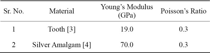
Table 1. Material properties (All dimensions in mm).
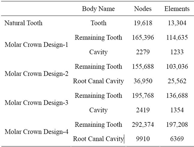
Table 2. Finite element summary.
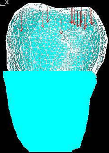
Figure 3. The natural tooth model is imported in ANSYS software and after meshing the geometry, load is applied on the occlusal surface of the tooth. The bone is assumed to be fixed. Figure shows loaded and constrained tooth model
The summary of the entire mesh generated for all the four molar crown design models in multiphysics environment is listed in Table 3. It also shows the type of elements used for meshing and their details.
5. RESULTS
For the masticatory loading (chewing) condition, FE analysis is carried out as discussed in the previous section. The solid model is imported from MIMIC software to the ANSYS Multiphysics Environment and material properties are assigned as per Table 1. Load of 1100 N is applied and the outer surface of the lower part of molar tooth is constrained for zero degree of freedom. This magnitude of load is analogous to load coming from mandibular jaw molar to maxillary jaw molar during
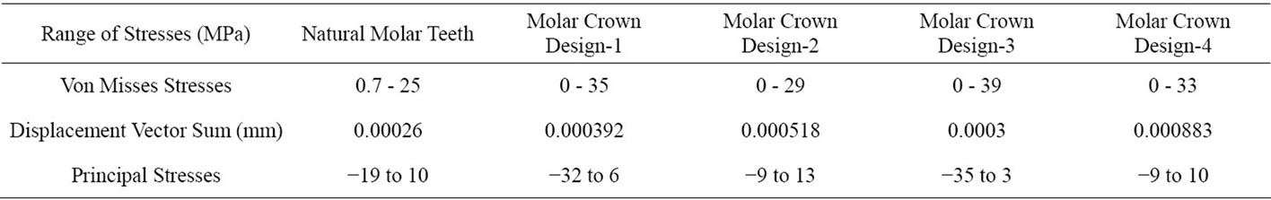
Table 3. Various stresses of all designs of molar crown and natural teeth.
normal chewing function. 3D models thus prepared are solved to get the final solution. The entire process is repeated for natural molar tooth and all the restoration of different designs of molar crown systems. The results are observed using post processing commands.
5.1. Discussion
For validation of the models, the stresses at a load of 1100N for all groups are extracted. For the given loading, design-1 and design-3 produces deformations similar to natural tooth of the order of 0.0003 mm. But the stresses induced are significantly large in these two designs as compared with design-2 and design-4. The compressive stresses induced in design-1 and design-3 are −32 and −35 MPa, which may lead to crushing of the remaining tooth structure surrounding the restorative material. Thus treatment may further worsen the strength of the restored tooth. A number of studies [6,7] analyzing biophysical stress and strain have shown that restorative procedures can make the tooth crown more deformable and teeth could be strengthened by increasing their resistance to crown deformation. The standard load case applied in the present analysis constitutes the most discriminating technique to study crown deformation. The results obtained with composite restored teeth (CPR) are in agreement with conclusions by Douglas [8] stating that their strength falls off with increasing cavity size and can only approach that of the unaltered tooth in the case of small conservative cavities. This cannot be said about silver amalgam and ceramic restored teeth (CER), the behavior of which is strictly mimicking the unaltered tooth. As illustrated in the present article, the proposed approach resulted in valid 3D models with very detailed tooth anatomy and realistic computation process. Previous attempt to generate 3D models resulted in much coarser meshes , mainly due to the limitation of the geometry acquisition method (manual tracing of actual tooth sections), another reason being the increased memory requirements for 3D models, which did not allow fine representation of the geometry. Other authors [9,10] digitized a plaster model (crown portion) and extrapolated the inner geometry (pulp, root dentin and enamel volumes) using tooth morphology literature data.
Different approaches were proposed to access the inner anatomical detail without extrapolation and accelerate the production of the models. When applied to small structures like teeth (with thin anatomical details such as the enamel shell), this technique does not allow the fine control of internal boundaries (e.g. dentin enamel junction), the exact geometry of which will have to follow the automatic volumetric meshing process.
The approach used in the present study suggests that maximum anatomical detail can be obtained by surface/ interface based meshing using stereo lithography (STL) surface data and .lis data. The different parts of the model featuring different mechanical properties are identified first (segmentation process) and meshed accordingly. Elements do not overlap the different structures but strictly follow the internal boundaries, resulting in a smooth and very well controlled representation of interfaces like the dentin enamel junction.
5.2. Conclusion
This investigation describes a rapid method for the generation of finite element models of dental structures and restorations. Detailed 3D finite element models of a molar Crown with different cavities and silver amalgam restorative materials were generated. Smaller cavities can be restored with strength quite close to that of natural crown. With a sufficient loss in tooth structure, retention capacity of foreign material in the restored tooth cannot be guaranteed. Few researchers [3,7] in past also performed similar studies and the results obtained by them closely matches the conclusion of the present study. Thus design-2 and design-4 results into better retention of the filling material. These two designs can withstand sufficient deformation under the loading and can induce stress much smaller than the design-1 and design-3. Thus design-2 and design-4 are highly recommended.
6. ACKNOWLEDGEMENTS
Author wishes to thank Mr. Ravi Rai for his contribution in procuring the CT data of the molar tooth and converting the scanned data to 3 D Model for further analysis.
![]()
![]()
REFERENCES
- Agoston, M.K. (2005) Computer graphics and geometric modelling, implementation and algorithm. Springer-Verlag Ltd., London, 48-49.
- Wheeler, R.C. (1984) Dental anatomy: Physiology and occlusion. 5th Edition, W.B. Saunders Company, Philadelphia.
- Rubin, C., Krishnamurthy, N., Capilouto, E. and Yi, H. (1983) Stress analysis of the human tooth using a three-dimensional finite element model. Journal of Dental Reseach, 62, 82-86.
- Wolfenden, A. and Hood, J.A.A. (1980) Young’s modulus and mechanical damping of sliver dental alloys. Journal of Materials Science, 15, 2995-3002. doi:10.1007/BF00550367
- Ochoa, O.O. and Reddy, J.N. (1992) Finite element analysis of composite laminates. Kluwer Academic Publication, Norwell.
- Morin, D.L., Cross, M., Voller, V.R., Douglas, W.H. and DeLong, R. (1988) Biophysical stress analysis of restored teeth: Modeling and analysis. Dental Materials, 4, 77-84. doi:10.1016/S0109-5641(88)80095-2
- Jantarat, J., Palamara, J.E. and Messer, H.H. (2001) An investigation of cuspal deformation and delayed recovery after occlusal loading. Journal of Dentistry, 29, 363-370. doi:10.1016/S0300-5712(01)00018-5
- Douglas, W.H. (1995) Methods to improve fracture resistance of teeth. In: Vanherle, G. and Smith, D.C., Eds., International Symposium on Posterior Composite Resin Restorative Materials, Peter Szulc Publishing Company, Amsterdam, 433-441.
- Ausiello, P., Apicella, A., Davidson, C.L. and Rengo, S. (2001) 3D-finite element analyses of cusp movements in a human upper premolar, restored with adhesive resinbased composites. Journal of Biomechanics, 34, 1269- 1277. doi:10.1016/S0021-9290(01)00098-7
- Ausiello, P., Rengo, S., Davidson, C.L. and Watts, D.C. (2004) Stress distributions in adhesively cemented ceramic and resin-composite class II inlay restorations: A 3D-FEA study. Dental Materials, 20, 862-872. doi:10.1016/j.dental.2004.05.001