Intelligent Information Management
Vol.2 No.3(2010), Article ID:1481,5 pages DOI:10.4236/iim.2012.23020
Can a Ris/Pacs System Really Improve Execution and Reporting Times?
1ASUR Marche, Zona Territoriale, Camerino Hospital, Italy
2ASUR Marche, Zona Territoriale, Macerata Hospital, Italy
3Department of Physics, University of Camerino, Via Madonna delle Carceri, Camerino, Italy
E-mail: roberto.murri@unicam.it
System (PACS), Computed Tomography (CT), Magnetic Resonance Imaging (MRI)
Received October 21, 2009; revised December 1, 2009; accepted January 6, 2010
Keywords: Radiology Information System (RIS), X-Rays (XR), Picture Archiving and Communication
Abstract
A study of the process timing and organization has been done in a Radiology Department where Radiology Information System (RIS) and Picture Archiving and Communication System (PACS) are working. The workflow times have been directly read from RIS database. In particular, Execution and Reporting steps were considered. Afterwards, data have been analyzed through a statistical elaboration and results were compared with data, coming from studies performed on similar process, collected with a stopwatch method. Possible “bottlenecks” can be evidenced in the process structure. Moreover, comparing hospitals with the same RIS/PACS system, different internal organization is emphasized.
1. Background
Many studies have showed the positive impact of the introduction of Radiology Information System (RIS) and Picture Archiving and Communication System (PACS) on the work organization of a Diagnostic Imaging Department. Kotter and Langer present results about the introduction of a RIS/PACS in a German Hospital [1]. Filmless and paperless operations are typical of a RIS/ PACS system. In fact, manually intensive tasks are reduced or eliminated. Reiner, Siegel et al., discuss the general situation and possible strategies for management optimization [2,3]. New working practices, following the introduction of RIS/PACS in an hospital, are discusssed by Shaw [4].
Workflow studies evidenced a significant reduction of the number of steps, needing to complete the process, after PACS utilization [2].
We collected data from Radiology Department of Macerata Hospital, equipped with a RIS/PACS system. RIS database was interrogated to measure process times for Execution and Reporting steps, two main parts of the whole image acquisition procedure, useful to analyze the workflow.
Results were compared with similar time data, manu ally measured and presented in a previous study [5]. In this work, Mariani, Tronchi, et al., cut the whole process in a number of steps with their elementary operations. Afterwards, they measured using a stopwatch method, the interval time needing for each elementary operation. The comparison of the data collected with two different methods can support a bottleneck analysis. Finally, we analyze differences in the organization of two other hospitals, but working with the same RIS/PACS digital system installed in Macerata Hospital.
2. Methods
A RIS/PACS system is working in the Radiology Department of Macerata Hospital since January 2004. This system offers several advantages, linked to the implementation of a speech recognition reporting technology, too.
RIS was interrogated to get a file containing data of about 33.000 examinations, performed from January 2005 to December 2005. The ethics committee of ASUR-Marche Z.T. 9 examined, before commencement of the study, the research proposal and the actual activity plan.
We considered only examinations on external patients and three exams: X-Rays (XR), Computed Tomography (CT) and Magnetic Resonance Imaging (MRI). Data were checked for anomalies and wrong values.
RIS records three times:
1) end of patient registration at Admittance Front Office;
2) end of the examination;
3) signature of the report.
The time interval from the end of the registration to the end of examination has been defined as T1’, Figure 1.
In this same figure, we define T2’ as time, running from the end of the examination to when film and report were available for delivery (Report Turnaround Time). A statistical elaboration was performed for collected times, computing their mean values with standard errors.
3. Results
Time frequency distribution of raw T1’ data for XR, is presented in Figure 2.
As one can see, about 45 % of the examinations is executed in 20 m or less, while about only 7 % takes a time ranging from 60 to 120 m. Similar histograms can be represented for CT and MRI: about 56 % of examinations is performed within 40 m for CT, as one can see in Figure 3, while the value decreases to about 42 % for MRI. All CT examinations are performed at maximum in 200 m, while the time increases to 240 m for MRI.
Figure 4 presents the time frequency distribution of raw T2’ data referring to XR: as one can see, about 49 % of the examinations is reported in 20 m or less and only about 10% takes a Reporting time longer than 140 m.

Figure 1. Execution and Reporting time diagram. T1 and T2 were manually collected, while T1’ and T2’ were read from RIS system. T1’-T1 and T2’-T2 differences were evidenced with dashed lines.
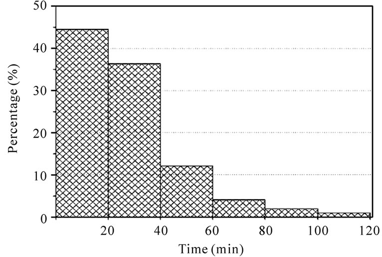
Figure 2. Histogram representing frequency density distribution for X-Rays Execution time (T1’). Data are for Macerata Hospital.
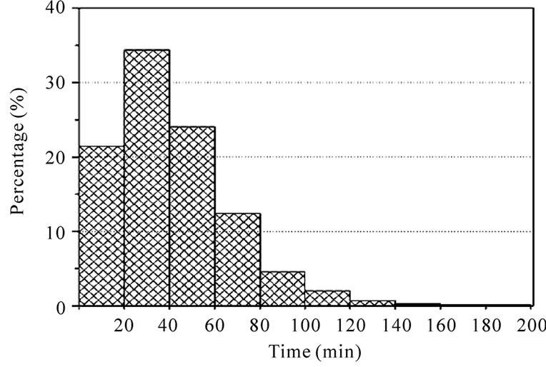
Figure 3. Histogram representing frequency density distribution for CT Execution time (T1’). Data are for Macerata Hospital.
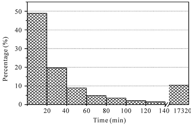
Figure 4. Histogram representing frequency density distribution of Macerata Hospital X-Rays Reporting time (T2’).
Similar histograms can be represented for CT and MRI. Figure 5 presents data for CT only. We can see that about 75 % of Reporting is done within 320 m, 20 % is reported in about 100 hours and the remaining 5 % needs longer time. For MRI, about 80% is reported in less than 260 m, while 95 % is completed in 44 hours.
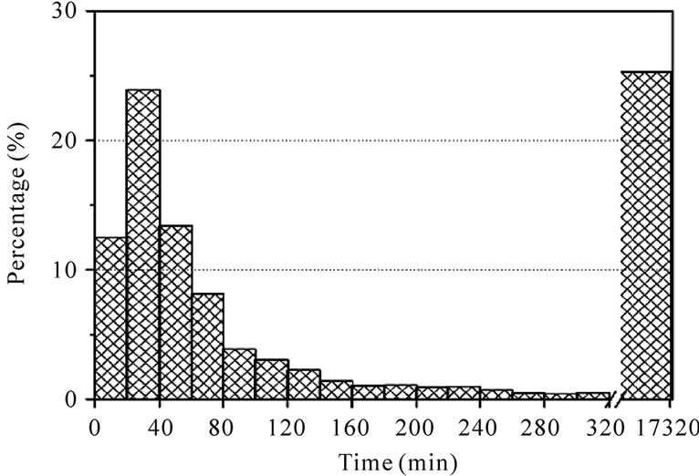
Figure 5. Histogram representing frequency density distribution of Macerata Hospital CT Reporting time (T2’).
Table 1 shows the mean times for each kind of exam.
4. Discussion
The discussion will be developed comparing data for Execution and Reporting steps, presented in this paper, with similar ones, collected performing a manual measure [5]. In this paper, C. Mariani, A. Tronchi et al., compared a traditional radiological workflow with one based on RIS/PACS system. X-Ray workflow process was considered in two different Radiology Departments. The study identified the main phases of the research work as Process Analysis, Data Collection and Elaboration, Interpretation and then defined the main steps of the whole image acquisition process. Finally, each step was divided in a number of elementary operations measuring the time required to complete each of these. Data collected were elaborated and synthesized to obtain time frequency distributions for each step and evaluation of the total time for the whole working flow. The statistical elaboration of the collected data shows that X-Ray working time decreases using RIS/PACS: the time reduction is between 35 % and 57 %.
Data of this work were elaborated with similar statistical procedures of the quoted article. Unfortunately, we have to work with different time intervals, due to different measuring methods (manual, stopwatch [5] and electronic, extracted from RIS/PACS, this work). However, we can give a positive meaning to the time difference. As one can see in Figure 1, T1 and T1’ don’t represent the same time interval. In fact, T1 is the net time of Execution, measured according to the stopwatch method, while T1’ is the time interval between the end of the Registration and the end of Examination. Their difference assumes the meaning of “patient waiting time” before the image acquisition. In this way, we can do an evaluation of the idle times, which cannot be directly measured by records
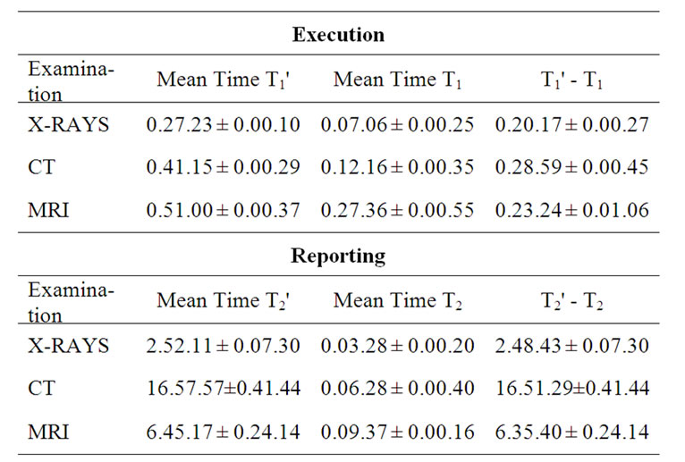
Table 1. Mean times for different type of examinations in Macerata Hospital. T1, T1’, T2 and T2’ are defined in Figure 1. Times coming from RIS are identified by prime. Time format: hours, minutes, seconds.
of the RIS system operating at Macerata Hospital. Using a RIS/PACS system there is, apparently, a hidden time interval, clearly evidenced when manual stopwatch procedure is used. In our opinion, this point needs both a better RIS software structure, able to taking into account the actual time when each elementary operation is really starting and a responsible management from the operators. Compared to data presented in [5], where the process is observed by the internal point of view of the operators, the patient is observing and evaluating the process, in this work. From these data, the waiting time seems to be a “reasonable” time, even if the patient can regard it as too long. The waiting time originates from different sources: insertion of urgent examinations among scheduled external patients; a possible modification of the procedure; enlarged preparation times for elders or disabled people and finally, technical troubles.
A better RIS software and a better management should have the common aim to equalize the external and internal points of view. Some other considerations on management will be done in the rest of discussion.
Similar considerations can be made on Reporting T2 and T2’ times. As one can see in Figure 1, T2 measures the net interval between beginning and end of Reporting step, while T2’ evaluates the time from the end of Execution to when report is available for delivery. T2’ must fit with the delivery time, in our case (Macerata Hospital) three days, defined by the operating procedures of local health service. In this sense, T2’ value seems to be an acceptable time interval.
(T2’ - T2) represents the time needing to the operators to start the drawing up of the Reporting. The time can be more or less long according to how the Regional Health Service and the Hospital are managed and then on how the Radiology Department can work: number of operators, inpatients examinations, urgent exams, need for different competencies,…etc. In our opinion, a point should be deeply investigated: the effective necessity of image examinations. But, we are entering, here, a different realm where the political anxiety to answer the patient requests, predominates.
The comparison of data acquired with manual or RIS procedure allows to evidence idle times and/or possible “bottlenecks” in the process workflow. How to solve bottlenecks is, in general, a problem needing discussions not only with the management of the whole structure, but also an internal reorganization of each operating unit.
In order to evidence possible differences coming from work organization among different Radiology Departments, we performed a comparison with similar RIS data read from San Severino Marche and Camerino Hospitals. These two last Hospitals are using the same Macerata RIS/PACS system.
In San Severino Marche Hospital, T1’ mean times (XR, CT and MRI) are longer than in Macerata Radiology Department, but their frequency distributions have similar structures, even if the histograms peak at different values. In fact, for CT the mean value is about 77 m for San Severino Marche Hospital, while it’s about 41 m for Macerata. The mean values for XR and MRI are, respectively, 50 m and 91 m at San Severino Marche Hospital, while they are about 27 m and 51 m for the other structure (Table 2).
The frequency distribution of T2’ in San Severino Marche has a dataset interval larger than Macerata one, for each kind of examinations. In particular for CT, Figure 6, about 50 % of the examinations is reported in 1300 m, while the remaining 50 % needs longer time. Histograms for XR and MRI present a structure similar to CT.
Similar results represent the frequency distributions of T1’ and T2’ in Camerino Hospital. Table 2 summarizes data for each kind of exams in these three Hospitals.
Several factors can be considered, in our opinion, to interpret the different structure of frequency distributions of T1’ and T2’ data among Macerata Hospital and the other two (San Severino Marche and Camerino). It could be coming from the different work organization of the Departments, from operator individual behaviours and from different work shifts. In fact, while in Macerata Hospital the radiologist work is concentrated in only one

Table 2. Mean values of T1’ and T2’ for different type of examinations in quoted Hospitals. Time format: hours, minutes, second.
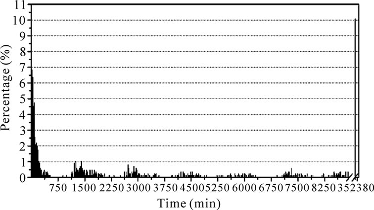
Figure 6. Histogram representing frequency density distribution of San Severino Marche Hospital for CT Reporting time (T2’).
Department, in San Severino Marche and Camerino Hospitals, each radiologist has to share on both structures, according to a weekly schedule. In this last situation, exams to report are piling up and time T2’ tends to rise. Moreover, the frequency distribution has a “packet” structure, with several peaks, as evidenced in Figure 6.
Other possible contributions could come from a smaller number of reporting workstations in Camerino and San Severino Marche than in Macerata Hospital, more exams for urgent and internal patients, and, finally, a lack of respect of booking time from several patients.
This explanation is supported comparing these results with data obtained from RIS database of Jesi Hospital. Figure 7 represents the frequency distribution of CT.
XR and MRI have very similar behaviours. The frequency distribution of process time evidences a “packet” structure similar to that of Camerino and San Severino Marche Hospitals. This structure supports the hypothesis that the flow of the work is not continuous but “pulsed”, according to the crossing of different radiologists, each starting a new reporting session, with different time intervals, following their time schedule of service. This data structure seems to be typical for traditional workflow. In fact, Jesi Hospital works with a RIS non interconnected with PACS.
A possible solution to this problem is very clear. Instead to move radiologists, move the images: teleradiology and, in general, telemedicine allow for a more regular exit data flux with shorter times. This solution fits well with other aspects: costs cutting, wider geographical coverage and less carbon dioxide emissions, due to reduced people movements.
Another point to be considered for possible ameliorations is to improve image analysis and elaboration using data mining procedures, to extract and retrieve patient data. Today's data could be useful for future diagnostic process, eventually avoiding new images acquisition.
5. Conclusions
A RIS/PACS technology allows to evaluate time intervals
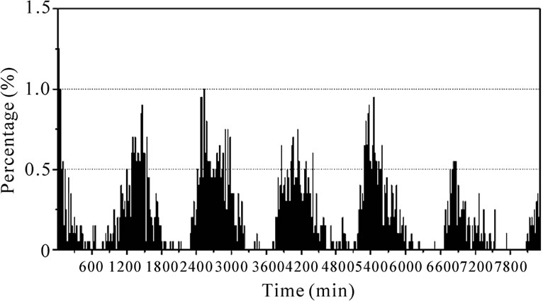
Figure 7. Histogram representing frequency density distribution of Jesi Hospital CT process time, as read from RIS database.
in a digital workflow and to analyze the activity of a Radiology Department. Bottlenecks and idle times of the workflow can be evidenced and, when possible, eliminated, according to the Department and Hospital organization.
Our results clearly show that different work organization of similar Radiology Departments is the main reason for the difference among time frequency distributions of the same diagnostic image process.
The role of Radiology Department organization and management is discussed, evidencing bottlenecks and how telemedicine can support the solution of several management problems.
6. Acknowledgements
The work was partially performed while C. Moretti was funded by a grant of ASUR Marche, Zona Territoriale 9, Macerata Hospital, Macerata (Italy), and while A. Tronchi was supported by a grant of Provincia di Macerata (Italy).
7. References
[1] E. Kotter and M. Langer, “Integrating HIS-RIS-PACS: The Freiburg experience,” European Radiology, Vol. 8, pp. 1707–1718, 1998.
[2] B. I. Reiner, E. L. Siegel, and J. A. Carrino, “Workflow optimization: Current trends and future directions,” Journal of Digital Imaging, Vol. 15, pp. 141–152, 2002.
[3] B. I. Reiner and E. L. Siegel, “The cutting edge: Strategies to enhance radiologist workflow in a filmless/paperless imaging department,” Journal of Digital Imaging, Vol. 15, pp. 178–190, 2002.
[4] R. Shaw “Integrating a PACS/RIS solution with new working practices to improve care,” Hospital Healthcare Europe (HHE), No. R11–R14, 2005/2006.
[5] C. Mariani, A. Tronchi, L. Oncini, O. Pirani, and R. Murri, “Analysis of the X-rays working flow in two diagnostic imaging departments with and without a RIS/ PACS system,” Journal of Digital Imaging, Vol. 19, No. (Suppl 1), pp. 18–28, 2006.

