Engineering
Vol.08 No.01(2016), Article ID:62914,10 pages
10.4236/eng.2016.81002
Finite Element Analysis for Groove Wander Prediction of Passenger Car Tires with the Longitudinal Tread Grooves
Kyoung Moon Jeong*, Sung Ju Kang, Hyoung Seok Kim, Kee Woon Kim
R&D Center, KUMHO TIRE Co. Inc., Yongin-si, South Korea

Copyright © 2016 by authors and Scientific Research Publishing Inc.
This work is licensed under the Creative Commons Attribution International License (CC BY).
http://creativecommons.org/licenses/by/4.0/


Received 29 December 2015; accepted 18 January 2016; published 21 January 2016
ABSTRACT
A finite element modeling technique is employed in this paper to predict the groove wander of longitudinal tread grooved tires. In generally, groove wander is the lateral force acting on a vehicle’s wheel resulting from the combination of rain grooves. If the lateral force of tire is generated by groove wander, unexpected lateral motion of vehicle will happen and it makes drivers uncomfortable. This paper describes the effect of groove wander according to the shape condition of tire tread groove and highway groove using the finite element analysis based on a static loading or a steady-state rolling assumption. The road groove can be located anywhere relative to the longitudinal tread groove. Therefore, the lateral force of the tire is changing depending on the location of the groove road. The numerical results for groove wander prediction of the longitudinal tread grooved tires are compared with the subjective evaluation. It is found that the waveform for the tire with varying grooved road position has a peak-to-peak lateral force in order to estimate the rating of groove wander. The effect of the road groove width and the pitch length on the peak-to- peak lateral force of tire is discussed. It is found that the prediction of FEA-based groove wander model using finite element analysis will be useful for the reliability design of the tire tread pattern design.
Keywords:
Groove Wander, Tire, Finite Element Analysis, Lateral Force, Tread Design

1. Introduction
Groove wander is a lateral force acting on a vehicle’s wheel resulting from the combination of rain grooves and contoured deformations in the road surface upon which the wheel runs [1] . The rain grooves greatly reduce wet traction accidents [2] . The car feels as if it is oscillating in the lateral direction [3] . It makes the driver nervous, and can lead to steering mistakes. The magnitude of groove wander is an indicator of quality to the driver and hence a concern to the tire manufacturer [4] [5] .
Tarpinian and Culp [2] observed that the number of coincidences between the tire tread pattern spacing and the rain groove spacing correlated with the driver’s subjective rating of groove wander. Their model assumes that the edges of tread elements become interlocked with rain grooves until the increasing lateral stress associated with normal lateral motion of the vehicle caused a sudden release, giving an impulsive effect. The same basic idea of tread/road groove interaction was applied to motorcycle tires by Doi and Ikeda [6] , but without taking coincidences into account. It works acceptably for tires with longitudinal grooves, but doesn’t work well for block patterns, curvilinear patterns, or zigzag tread patterns [1] [7] . Tire companies had to depend on road tests to design treads to minimize groove wander.
As reported by Peters [1] , an indoor test designed to replace road testing led to the suggestion by test engineers at Smithers Scientific Services that the real source of groove wander was simple modulation of the lateral stress field in the footprint of the rolling tire because small lateral movements made the stress field oscillate in a repeatable fashion each time the lateral motion of the car took it across a groove spacing. He applied finite element analysis to the stress field for tires with a variety of tread patterns and predicted that the lateral force waveform would look like the one portrayed. This waveform is quite similar to the one obtained from the indoor experiments. Nakajima [7] applied the same concept used in Peter [1] ’s work and obtained an excellent correlation to subjective ratings by drivers. He shows subjective ratings of groove wander by the test driver as a function of the computed peak-to-peak amplitude of the lateral force waveform resulting from tire interaction with longitudinal groove in the pavement. Although finite element analysis can provide detailed information about tire deformation, stress-strain, temperature distribution, and rolling resistance, tire designers still find it difficult to establish relationships between tire performance and its parameters. To the authors’ knowledge, no parametric study for groove wander analysis has been reported in the open literature.
This paper is to estimate the effect of the tire tread groove on the groove wander in the different grooved highways using the finite element analysis based on a static loading or a steady-state rolling assumption. The road groove as shown in Figure 1 can be located anywhere relative to the tread element. Therefore, the lateral force of the tire is changing depending on the location of the grooved road. It is found that the waveform for the tire with varying grooved road position has a peak-to-peak lateral force in order to estimate the rating of groove wander. The effect of the road groove width and the pitch length on the peak-to-peak lateral force of tire is discussed. The results of finite element analysis on the groove wander of 3-D smooth tire with the longitudinal groove are compared the subjective experimental data for three rain groove profiles.
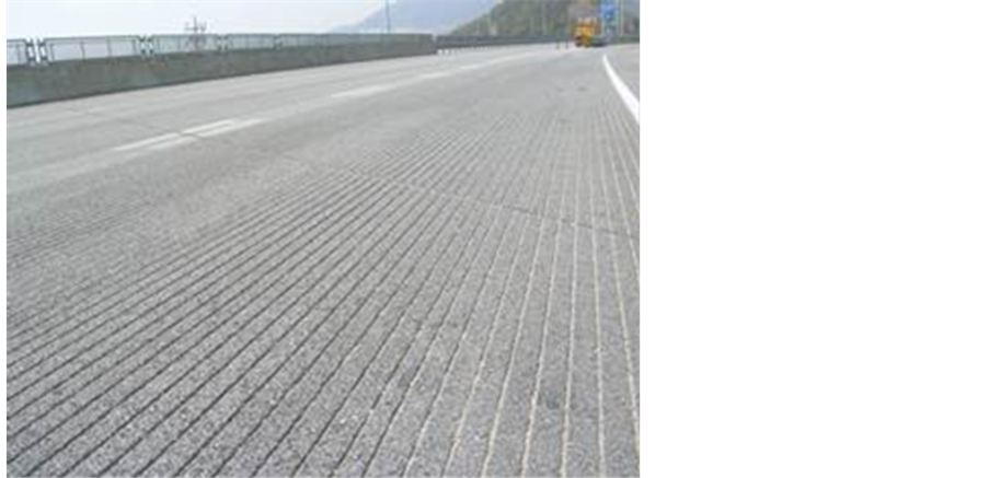
Figure 1. The rain grooved road.
2. Finite Element Modeling
2.1. Tire Model
A tire usually consists of several rubber components, each of which is designed to contribute to some particular factors for tire performance in addition to several cords and rubber composites. These components play a role in maintaining the stiffness and strength required in a tire. Figure 2 shows the general structure of a radial tire used in automobile, where the roles of tire components are well described in a book by Clark [8] . The material composition of most tires is distinguished largely into the fiber-reinforced rubber (FRR) parts and the remaining pure rubber part. The FRR parts of the tire model considered here are composed of a single-ply polyester carcass, tow steel belt layers, and several steel bead cords. Since the FRR parts are in the highly complex structure, their material models are chosen based on the goal of the numerical simulation. In the static tire analysis, those parts are usually modeled using solid elements like rebar elements [9] [10] , and which does not make too much trouble in aspect of CPU time. However, in the dynamic tire analysis this full modeling requires extremely long CPU time, so the FRR parts are modeled as either composite membrane or composite shell. In the current study, two belt layers in underlying rubber matrix and a carcass layer shield with innerliner are modeled using rebar elements. On the other hand, steel cords and underlying rubber matrix in the bead region are modeled as homogenized solid.
Rubbers except for the FRR parts are modeled by the penalized first-order Mooney-Rivlin model [8] [9] in which the strain density function is defined by
 (1)
(1)
where  are the invariants of the Green-Lagrangian strain tensor and
  and
and  are the rubber material constants determined from the experiment. On the other hand,
  is a sort of penalty parameter controlling the rubber incompressibility. The shear modulus
  and the bulk modulus
  of rubber are related as
 and
and , from which one can easily obtain the following relation for Poisson’s relation:
 . It is clear that the incompressibility of rubber is asymptoti-
cally enforced as the penalty parameter approaches infinity, but the choice of  near 100 is usually recommended for the stable transient dynamic response with the reasonable time step size.
Rebar is used to define the layer of uniaxial reinforcement in a membrane, a shell and the surface elements. The layer is treated as a smeared layer with a constant thickness equal to the area of each reinforcing bar divided

Figure 2. Structure of automobile radial tire.
by the reinforcing bar spacing. Since the angle and spacing of fiber reinforcements are changed during manufacturing process, angle and spacing of rebar at each location in a tire should be determined using the following lift equations. Assuming the deformation during manufacturing process in purely due to pantographic action, the angle and spacing of rebar in the cured tire can be obtained by
 (2)
(2)
where ,
,  ,
,  and
and  are spacing, angle, radius and elongation factor of fiber reinforcements after lift. And
 ,
,  and
and  are spacing, angle and radius of them on a tire building drum.
Figure 3(a) shows a two-dimensional finite element model generated by solid-modeling program, in which 4-node quadrilateral and 3-node triangular elements are used. The three-dimensional finite element model as shown in Figure 3(b) is generated by rotating the two-dimensional cross section of a finite element through a 360˚ and is defined the unequal angular increments. In order to obtain the more accurate result of finite element analysis, the 3-D tire model contains very small segments (2.0 deg.) at the contact part as shown in Figure 3(b).
2.2. Road Design
Figure 4 shows the rain groove profile. Longitudinal grooves are ground into highways to improve wet traction performance. For example, most major freeways around Los Angles, California are grooved. Although rain groove profile and spacing in road pavements are not standardized, the design is chosen by the State of California with width 3.2 mm, height 3.2 mm, and pitch length 19.1 mm. In order to obtain the effect of rain groove profiles on the groove wandering, we chose the various road profiles.
3. Groove Wander Analysis
3.1. Subjective Evaluation
In order to measure the subjective rating of groove wander, an HMC MD Avante car is used in this paper. Field measurements of vehicle wander are carried out on a 40 km highway between Songtan and North Jincheon (Pyeongtaek and Eumseong highway) in South Korea. One expert driver took part in the subjective evaluation exercise with over 10 years. Table 1 is three road profiles along the specific highway section. Subjective test is repeated three times at the velocity of 80 km/h. A tire with a size of P205/55R16 is used for the test of vehicle

 (a) (b)
Figure 3. Finite element modeling of P215/45R17 tire. (a) 2-D model; (b) 3-D model.

Figure 4. The rain groove profile.

Table 1. Road profiles at the highway.
wander. During testing the roadway was dry and free of major debris. Some smaller debris such as sand was present, but was deemed to be normal and did not interfere with testing. The roadway was free of potholes and major cracking. There was very minimal wind observed throughout testing. The subjective evaluation is divided into four levels depending on the effect of the groove wander. The first level does not cause the groove wander. Level 2 or 3 is the degree of specialist cognitive or public recognition. The fourth level is a very large groove wandering occurring.
3.2. Validation of Finite Element Analysis
In order to validate FEA-based groove wander model, the same set of eleven tires tested at the highway are checked with the model. Figure 5 shows interaction between tread pattern grooves and pavement grooves. As the tire moves laterally in the direction shown, its outside groove G1 is the first to be trapped by a road surface. As the tire continues to move laterally by a distance Y, further trappings will occur at distances. Tire is moved by a pitch length to the lateral direction. In this paper, tire is moved 30 times regardless to the pitch length. Figure 6 shows the result of the lateral force waveform using FEA-based groove wander model. The waveform for this case of four grooves with varying grooved road position has a peak-to-peak lateral force of 40.0 N predicted. Every element within a tire footprint would experience this effect on a grooved road, therefore much larger lateral force variations could be generated as contributions from individual tread elements are combined. As these lateral force increase, vehicle lateral accelerations increase, leading to drivers and passengers feeling groove wander.
The correlation between prediction and measurement is shown in Figure 7. The horizontal axis is the predicted peak-to-peak lateral force, and on the vertical axis is the subjective rating based on the 4-point scale. Figure 7 shows an increase correlation between the predicted peak-to-peak lateral force and the measured subjective rating with an R2 of 0.78. The FEA-based groove wander model can be used as a pass-or-fail screening tool for the tire tread designs related to width, number, and position of the longitudinal groove. The mesh size of the tire model is an important consideration, because it influences the accuracy of the results as well as the computational time for solving the problem. In order to verify the accuracy of the finite element analysis of the groove wander analysis, we determined the mesh size with about 4.0 mm of the finite element modeling of the tire presented in this paper by trial and error.
4. The Effect of Rain Groove Profiles
In order to analyze the effect of the specific road profile on the groove wander, we calculated the lateral force generated by the interaction between tread pattern grooves and pavement grooves. The lateral force of the tire is changed according to the position of each road surface groove. One or more waveforms are displayed differently based on the pavement groove position in the pitch length of the road surface. We analyzed the effect of the rain groove profiles according to the design of the longitudinal groove intervals and a road surface of a tire tread groove pattern using the calculated peak-to-peak lateral force.
4.1. Specific Road Profiles
The tires used in this paper are P215/45R17 with four longitudinal groove and P165/60R14 with three longitudinal grooves in circumferential direction as shown in Figure 8. Figure 9 shows the finite element modeling with three or four longitudinal grooves of passenger car tires. The internal pressure and vertical loading are 32 psi, 450 kgf in P215/45R17 and 33 psi, 350 kgf in P165/60R14. A coefficient of friction, 0.8, is applied to tire/ ground contact surface for the contact loading. And, frictional coefficient between tire bead area and rim is 0.3. The finite element program ABAQUS/Standard [9] is employed for the analysis.
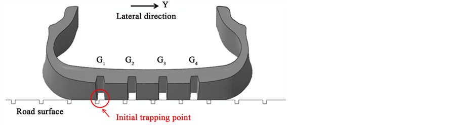
Figure 5. Interaction between tread pattern grooves and pavement grooves.

Figure 6. Lateral force waveform.

Figure 7. Correlation of FEA-based groove wander model to subjective rating.
The width and the pitch length on the specific road pavement of Korea (#A-#F) and Los Angles (#LA) are classified as Table 2. We analyzed the effect of road profiles on the groove wander by calculating the peak-to- peak lateral force on each road surface. The footprint pressure distributions with respect to several road profiles obtained by the finite element analysis are represented in Figure 10. Figure 11 shows the lateral force waveform generated in the various road designs with the width and the pitch length. The each pitch length in the lateral position is divided into at intervals of thirty. We can obtain thirty lateral forces with respect to one road groove profile. It is shown that the lateral force generates one or more waveforms with respect to the width and the pitch length of road design.

 (a) (b)
Figure 8. Passenger car tires. (a) P215/45R17; (b) P165/60R14.

 (a) (b)
Figure 9. Finite element models of passenger car tires. (a) P215/45R17; (b) P165/60R14.
 (a) (b)
Figure 10. Footprint pressure distributions. (a) P215/45R17; (b) P165/60R14.
 (a) (b)
Figure 11. Lateral force waveform with respect to road profiles. (a) P215/45R17; (b) P165/60R14.
Table 2. Road design with respect to width and pitch length (unit: mm).
Figure 12 shows the peak-to-peak lateral force with respect to road profile. It is shown that the peak-to-peak lateral force of Korea road profile is larger than that of the LA road profile. Therefore, Korea road profile is relatively harsh than LA road profile. It is found that ranking of peak-to-peak lateral force of the tire on the relatively small width of the road surface groove can be changed according to tire size or the number of the tread pattern groove. However, the change of the pitch length with the width, 9 mm, is similar with respect to the tire size. It is shown that when the pitch length is increased, the peak-to-peak lateral force decreases.
4.2. Parametric Study
In the previous Section 4.1, we found that the peak-to-peak lateral force increases as the width of the road groove increases. In order to analyze the effect of the road groove width and the pitch length on the groove wander, we determined the road designs as shown in Table 3. The peak-to-peak lateral force is found for each different the width and the pitch length.
Figure 13 shows the lateral force waveform with respect to each road design. The peak-to-peak lateral force with respect to each road design is shown in Figure 14. The peak-to-peak lateral force decreases as the pitch length with the constant groove width increases. The peak-to-peak lateral force increases as the groove width increases.
In order to analyze the effect of vehicle speed on the groove wander, a steady-state transport scheme is applied for rolling analysis, and different vehicle speed. As with well-known procedures for axisymmetric tires [11] - [15] , the procedure uses a mixed Eulerian/Lagrangian kinematic described in an Eulerian manner and relative deformation is described in a Lagrangian manner. Figure 15 shows peak-to-peak lateral force with respect to the vehicle speeds and the road groove designs. It is shown that the peak-to-peak lateral force increases as the vehicle speed increases. And, the peak-to-peak lateral force decreases as the pitch length increases. The results predicted here agree with the previous results in [16] .
 (a) (b)
Figure 12. Peak-to-peak lateral force with respect to road profile. (a) P215/45R17; (b) P165/60R14.

Figure 13. Lateral force waveform with respect to road design.

Figure 14. Peak-to-peak lateral force.

Figure 15. Peak-to-peak lateral force with respect to speed.
Table 3. Road design with respect to width and pitch length (unit: mm).
5. Conclusion
The finite element modeling technique is employed for the calculation of the peak-to-peak lateral force to predict the effect of the rain groove profiles on the groove wander, based on the static loading analysis or the steady-state rolling analysis. The road groove can be located anywhere relative to the tread element. Therefore, the lateral force of the tire is changing depending on the location of the road groove. The effect of the change of the rain groove profiles on the groove wander is analyzed. And also, the effect of the road groove width and the pitch length on the peak-to-peak lateral force of tire is discussed. It is found that the effect of the groove width of the road is larger than that of the pitch length. Therefore, this study will be useful for the tire tread design to minimize groove wander.
Acknowledgements
This research was financially supported by the “Development of high performance components for premium vehicle” through the Ministry of Trade, Industry & Energy (MOTIE) and Korea Institute for Advancement of Technology (KIAT).
Cite this paper
Kyoung MoonJeong,Sung JuKang,Hyoung SeokKim,Kee WoonKim, (2016) Finite Element Analysis for Groove Wander Prediction of Passenger Car Tires with the Longitudinal Tread Grooves. Engineering,08,11-20. doi: 10.4236/eng.2016.81002
References
- 1. Peters, J.M. (2001) Application of the Lateral Stress Theory for Groove Wander Prediction Using Finite Element Analysis. Tire Science and Technology, 29, 244-257.
http://dx.doi.org/10.2346/1.2135242 - 2. Tarpinian, H.D. and Culp, E.H. (1997) The Effect of Pavement Grooves on the Ride of Passenger Cars—The Role of Tires, Society of Automotive Engineers. SAE 770869, Warrendale.
- 3. Yoon, H.J. and Kim, J. (2013) Design of a Signal Transducer for Direct Conversion of Wheel Linear Accelerations into Tire Lateral Forces. International Journal of Automotive Technology, 14, 897-902.
http://dx.doi.org/10.1007/s12239-013-0098-8 - 4. Bruke, A.M. and Olatunbosun, O.A. (1997) Static Tyre/Road Interaction. Meccanica, 32, 449-457.
http://dx.doi.org/10.1023/A:1004259917697 - 5. Gent, A.N. and Walter, J.D. (2005) The Pneumatic Tire. U.S. Department of Transportation, National Highway Traffic Safety Administration.
- 6. Doi, T. and Ikeda, K. (1985) Effect of Tire Tread Pattern on Groove Wander of Motocycles. Tire Science and Technology, 13, 147-153.
http://dx.doi.org/10.2346/1.2150992 - 7. Nakajima, Y. (2003) Prediction of Rain Groove Wandering. Vehicle Systems Dynamics, 40, 401-418.
http://dx.doi.org/10.1076/vesd.40.6.401.17910 - 8. Clark, S.K. (1982) Mechanics of Pneumatic Tires. U.S. Department of Transportation, National Highway Traffic Safety Administration.
- 9. ABAQUS (2010) Analysis User’s Manual. Version 6.10, Dassault Systemes Simulia, Inc.
- 10. Helnwein, P., Liu, C.H., Meschke, G. and Mang, H.A. (1993) A New 3-D Finite Element Model for Cord-Reinforced Rubber Composites-Application to Analysis of Automobile Tires. Finite Element Analysis and Design, 14, 1-16.
http://dx.doi.org/10.1016/0168-874X(93)90075-2 - 11. Kenndy, R.H. (1985) Three Dimensional Finite Element Methodology for Steady State Rotation with Application to the Tire. Ph. D. Dissertation, University of Akron.
- 12. Oden, J.T., Lin, T.L. and Bass, J.M. (1988) A Finite Element Analysis of the General Rolling Contact Problem for a Viscoelastic Rubber Cylinder. Tire Science and Technology, 16, 18-43.
http://dx.doi.org/10.2346/1.2148795 - 13. Nasdala, L., Kaliske, M., Becker, A. and Rothert, H. (1998) An Efficient Viscoelastic Formulation for Steady-State Rolling Structures. Computational Mechanics, 22, 395-403.
http://dx.doi.org/10.1007/s004660050371 - 14. Zheng, D. (2003) Prediction of Tire Tread Wear with FEM Steady State Rolling Contact Simulation. Tire Science and Technology, 31, 189-202.
http://dx.doi.org/10.2346/1.2135268 - 15. Qi, J., Herron, J.R., Sansalone, K.H., Mars, W.V., Du, Z.Z., Snyman, M. and Surendranah, H. (2007) Validation of a Steady-State Transport Analysis for Rolling Treaded Tires. Tire Science and Technology, 35, 183-208.
http://dx.doi.org/10.2346/1.2768974 - 16. Han, J.-H., Lee, D.-M., Hwang, S.-W. and Kim, B.-S. (2010) The Study on the Characteristics of Groove Wandering and Noise Caused by the Design Parameter of Longitudinal Groove on the Tire’s Pattern. Proceedings of Korean Society for Noise & Vibration Engineering Conference, 700-701.
NOTES

*Corresponding author.