Engineering
Vol. 5 No. 9 (2013) , Article ID: 36177 , 7 pages DOI:10.4236/eng.2013.59083
Remote Laser Welding with High Power Fiber Lasers
Laboratory of Welding Technology and Laser Processing, Department of Mechanical Engineering, Lappeenranta University of Technology, Lappeenranta, Finland
Email: Paul.Kah@lut.fi
Copyright © 2013 Paul Kah et al. This is an open access article distributed under the Creative Commons Attribution License, which permits unrestricted use, distribution, and reproduction in any medium, provided the original work is properly cited.
Received May 24, 2013; revised June 24, 2013; accepted July 1, 2013
Keywords: Remote Laser Welding; Scanner; Fiber Laser; Process Parameters
ABSTRACT
The introduction of the high power fiber laser with brilliant beam quality has enabled the rapid development of remote laser welding (RLW). This paper presents a theoretical review of remote laser welding. As a promising technology, RLW offers increased flexibility, high operational speed, and reduced cycle time to process a wide range of workpieces. This study presents the typical characteristics of RLW with high power fiber lasers. It also investigates the influence of process parameters such as laser power, welding speed, shielding gas supply, beam inclination and focal position on the weld seam quality.
1. Introduction
Remote laser welding (RLW), a non-contact robotic laser welding technique, has been developed and implemented to improve the productivity and flexibility of conventional laser welding [1]. The first experimental analysis of RLW was reported by John Macken in 1996 [2]. The remote welding process is characterized by a long focal length (up to 1600 mm), a high-power and brilliant-quality laser source, and beam deflection by the scanner [3-5]. Compared to conventional laser welding, the remote welding technology offers increased flexibility, higher working speed, and reduced cycle time [3,6].
Thus far, RLW has been studied and implemented with a variety of high-power laser sources. In [1], the RLW systems are implemented with CO2 and Nd: YAG lasers. In [7], the RLW experiments are carried out with Nd: YAG and disk lasers. RLW applications with highpower fiber lasers have been introduced in [6,8]. With a wavelength of 1080 nm, these high-power fiber lasers enable beam delivery through the fiber, enhancing spatial flexibility and accurate focusing. By contrast, it is impossible to deliver the beam of CO2 lasers via an optical fiber due to its rather long wavelength of 10.6 µm [7]. The suitable wavelength of high-power fiber lasers, combined with excellent beam quality, makes them a promising alternative to conventional CO2 and Nd: YAG lasers in RLW applications.
The operating principle of RLW is normally based on using a scanner to deflect and position the laser beam onto the surface of the workpiece travelling at high speed [9] and, at present, 2D-scanners are the most widely adopted scanners in remote welding applications. The 2D-scanner unit is a galvanometer system, in which two lightweight mirrors are used and rotated by motors. The system can handle a laser power of up to 5 kW and is more economical than 3D-scanners [10].
Remote laser welding the technology is not yet very widespread, although it clearly has potential in the automotive industry, such as in the seating, body in white and interior parts. RLW has replaced resistance spot welding with its increased laser usability rate and reduced process times in car body construction [6].
However, RLW still faces many challenges; in predicting process behavior, in ensuring acceptable and reliable weld quality, and in dealing with issues such as shielding gas supply, clamping and coated sheet metals [11,12]. Compared to conventional laser welding, a greater number of process parameters have to be taken into account in remote welding applications. These parameters can be primarily divided into the areas of beam quality, processing parameters, and material properties [6].
2. Remote Laser Welding
2.1. Principle
Remote laser welding is not a new technology, but is based on the principle where a scanner deflects and positions the focused laser beam over the workpiece from a distance of typically 1000 - 1600 mm [13]. The first experiment in laser keyhole welding with 1600 mm focal length, by John Macken in 1996, is acknowledged as forming the cornerstone of remote laser welding technology [11]. The scanner enables the translation of the laser beam into large working areas of 1m × 1 m or over 2 m3 3D working volume with a welding speed of up to 30 m/min [14].
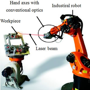
Remote laser welding can be principally implemented with two modes; the scanner-integrated system and the robot-based system [15]. The scanner-integrated system utilizes a scanning unit (usually a 2D scanner) for positioning and focusing of the laser beam, as shown in Figure 1(a) [11]. RLW with the robot-based system is accomplished with a long focal length laser optic and a 6- axis robot, in which the robot serves for positioning of the laser beam on the surface of the workpiece, as illustrated in Figure 1(b) [11].
Compared to robot-based RLW, the scanner-integrated RLW system offers shorter processing times and higher accuracy in many applications. However, the laser beam quality requirements of scanner-integrated RLW are much higher than for robot-based RLW systems. Table 1 presents the typical performance of scanner-integrated and robot-based RLW systems versus conventional laser welding.
2.2. Requirements
The typical requirements for RLW to make sound welds can be divided into three categories: the scanner for delivering and positioning the beam adequately, a highpower laser with sufficient quality for the long focal length of the system, and proper control of process parameters [16].
2.2.1. Scanner
The scanner is used to guide and rapidly position the beam on the surface of the workpiece along the desired weld path [16]. The lightweight and highly dynamic scan head enables extremely fast movement of the laser beam between welds, which means that positioning requires much less time than in the conventional laser welding process [17].
Figure 2 shows the typical elements of a scan head [9]. A scanner unit consists of a group of mirrors and lenses [9,18]. In remote welding, the laser beam first passes through the lenses. The smaller lens moves along the optical axis in order to change the focal position. Afterwards, the laser beam is deflected and guided successively by the mirrors X and Y. Finally, the laser beam is focused on the workpiece precisely along the desired weld seams [9]. Figure 3 illustrates a classic 2D-scanner system including a seam tracking sensor, a line projector,
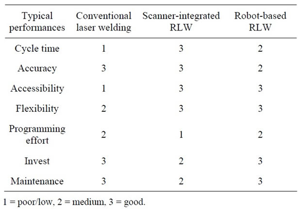
Table 1. Comparison of remote and conventional laser welding processes [4,13,15].
 (a)
(a)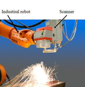 (b)
(b)
Figure 1. (a) Scanner-integrated RLW system and (b) Robot-based RLW system without scanner optics [11].
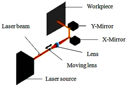
Figure 2. Typical elements of a scan head [9].
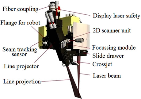
Figure 3. Main components of the 2D-scanner system [19].
and a high dynamic 2D-scanner unit [19].
2.2.2. High-Power Fiber Laser
High-power fiber lasers have recently been developed with attractive characteristics for materials processing applications [20]. High-power fiber lasers with brilliant beam quality can produce ultra-high peak power density of several MW/mm2, which is important for high speed RLW with long focal length [21].
Based on a number of studies, high-power fiber lasers have multiple advantages, such as [22,23]:
● High electric efficiency.
● Excellent beam quality.
● Relatively low operational costs due to the long lifetime.
● High flexibility in production because of the beam delivery with fibers.
● High absorption coefficient for thin sheets of most metals.
● Compact design and mobility.
Figure 4 shows an RLW cell with a high-power fiber laser anchored by a robot and equipped with welding head fixtures. It has been shown that remote fiber laser welding allows an increase in weld processing speeds, a reduction in consumables, such as weld wire and weld guns, less tooling and part fixturing, and a decrease in on-going maintenance costs typically associated with conventional welding processes [24].
2.3. Typical Characteristics of RLW
Remote laser welding integrated with a scanner offers a number of advantages over conventional laser welding, for example, high flexibility, reduced cycle time, high speed production of sound welds with consistent quality, a high degree of automation, good accessibility to the weld joints due to the long focal length, cost savings through the use of less materials and reduced maintenance demands; low distortion from a smaller heat input, and small floor space requirements [25,26].
2.3.1. High Productivity of RLW
Scanner-integrated RLW offers high productivity on account of its high welding velocity and reduced cycle time. The welding speed is dependent on the laser power used, which is normally 6 m/min and up to 30 m/min for special plates [27]. A remote fiber laser welding system can weld more than twice as fast as either MIG or resistance spot welding [24]. The elimination with the scanner of non-productive time means that the cycle time of RLW can be reduced by up to 80% [4,27]. The continuous motion of the scanner head in combination with the rapid positioning makes the RLW system move the laser beam between welds in less than 50 milliseconds, while robot positioning typically takes 2 - 3 seconds [3,17]. Hence, the cycle time of the scanner-integrated RLW is 6 - 10 times faster than resistance or arc welding processes [3].
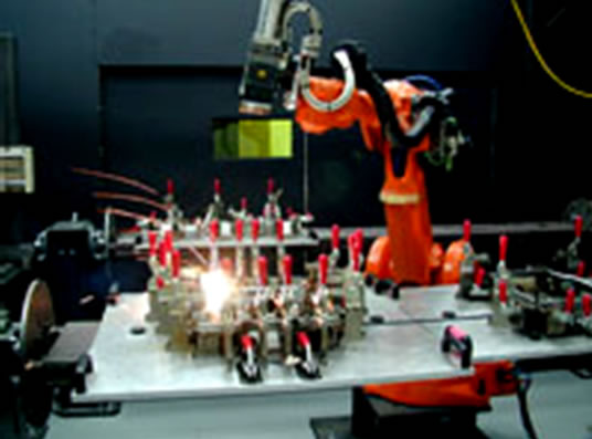
Figure 4. RLW cell with a 5 KW IPG fiber laser [24].
2.3.2. High Flexibility of RLW
The long working distance between the scanner head and the workpiece in RLW enables high flexibility in the processing of joints that conventional laser welding cannot reach. As illustrated in Figure 5, the seam can only be welded with a long working distance. Another benefit of the long working distance is the avoidance of plume and spatters from optical elements [3,11]. The long working distance also allows the use of simpler clamping fixtures and makes RLW more profitable in big-size product applications [15].
2.3.3. Low Costs of RLW
RLW has shown great potential for cost savings in the body shop. Based on a number of studies [3,12,25,28], the RLW system can decrease manufacturing costs in many ways: reduction of average operating costs by mass production, reduction of costs by reduced number and increased efficiency of the laser guns, reduction of materials usage by a narrower joint overlap, and low maintenance costs due to the long lifetime.
Nevertheless, RLW also has disadvantages, for example, in regard to shielding gas supply, laser quality demand, clamping, and seam tracking [15,29]. Shielding gas supply is the biggest challenge for RLW, primarily because of the long working distance. The shielding gas has to be supplied to the workpieces independently [4,30]. The assistant gas does not move along with the welding seams but keeps the entire processing zone in a shielded environment. A number of nozzles are commonly required to work together simultaneously with a high gas flow rate, in order to protect the welding zone from oxidation and remove contamination. Therefore, the shielding gas consumption in RLW is high, which adversely affects total operational costs [11,12].
2.4. Applications of RLW
Currently, RLW is mainly applied in the mass production of flat assembly groups in which a high number of weld-
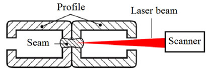
Figure 5. RLW of limited working zone [11].
ing seams are being processed [11]. One typical area benefiting from RLW is the automotive industry [13,25]. Today, nearly 70 RLW systems are used for many automotive applications, such as seating (recliners, frames, tracks, panels), body in white (trunks, rear panels, doors/hang on parts, side walls, pillars, heat exchangers), and interior fittings (IP beams, rear shelf/hat rack) [16, 31].
3. Process Parameters of RLW
Process parameters such as speed, focal position, beam inclination, shielding gas, and joint design, as well as material properties have been examined and studied in efforts to improve beam characteristics such as laser power, beam quality, wavelength, focal diameter and focal length, mode and polarization [32-34]. The key parameters of RLW, that is, boundary conditions, process conditions and process quality, as illustrated in Figure 6, have been researched and reported by Oefele et al. [6].
RLW with fiber lasers has been studied with four types of steels: mild steel [6,15], galvanized steel [35], galvannealed steel [8], and stainless steel [36]. The main processing parameters are given in Table 2.
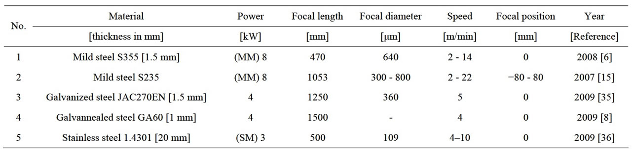
Table 2. Process parameters of RLW with fiber lasers.
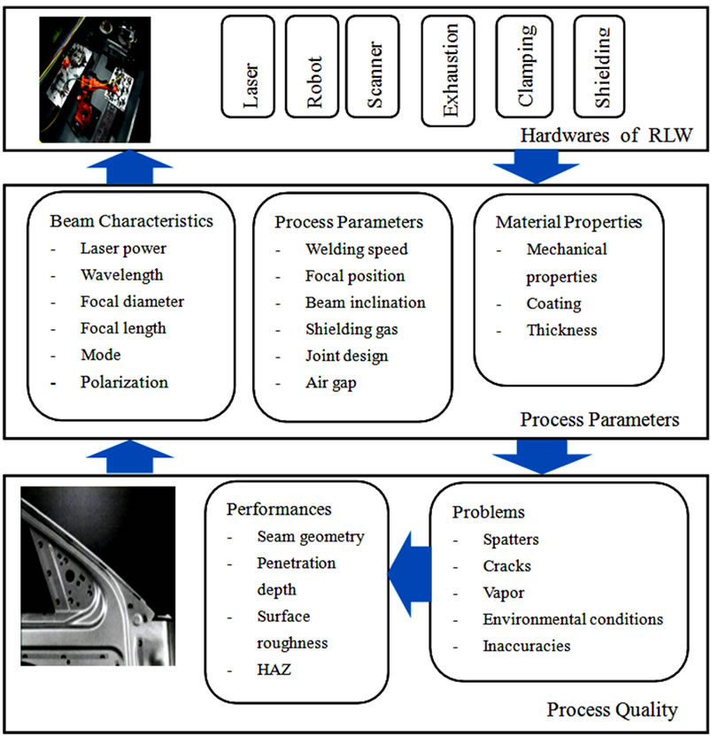
Figure 6. Key parameters of RLW [6].
A number of processing parameters of RLW with fiber lasers have been investigated, such as laser power [6], welding speed [36], shielding gas supply [15], beam inclination [6], and focal position [15].
3.1. Laser Power
In laser processing, increased power of the laser gives increased welding speed. It has been reported that an increase in fiber laser power from 4 kW to 8 kW for the remote welding of mild steels with a constant focal diameter will result in increased welding speed. On the other hand, an increase in spatter, seam sagging, and decrease in seam quality will be associated with the increase of welding power [6,37].
Figure 7 illustrates the influence of laser power on welding speed and penetration in the remote fiber laser welding of mild steel S355. It can be seen that an increase in laser power results in a higher welding speed at the same penetration depth [6].
3.2. Welding Speed
Welding speed is one of the most important factors in RLW. It is generally dependent on the power density, required penetration, laser mode, focal position, and the number of rescans. Welding speed has an effect on the weld pool, weld bead shape, and penetration depth [33].
Figure 8 shows the influence of welding speed on the welding depth in the remote fiber laser welding of stainless steel 1.4301 with different laser powers. It can be seen that the welding depth decreases with increase in welding speed. At the same time, the welding depth increases with increases in laser power [36].
3.3. Shielding Gas Supply
Shielding gas supply offers numerous benefits to RLW: protection of the interaction zone from oxidation, removal of metal vapor and particles from the laser beam path, and stabilization of the welding process from plasma initiation [38]. The most common shielding gases used in RLW of steels are argon, helium, nitrogen, and compressed air [39]. A typical shielding gas flow in RLW is approximately 15 - 20 l/min, depending on the length of the welds [4].
The influence of shielding gas on the welding depth and speed of high power remote fiber laser welding is shown in Figure 9. The penetration depth decreases constantly with increase in the welding speed, with or without shielding gas. The influence of shielding gas on the penetration depth is very strong when the welding speed is less than 5 m/min. The main reason is probably the great plume of metal vapor produced in the keyhole, which hinders the welding process. With a welding speed over 14 m/min, the shielding gas has an insignificant effect on the penetration depth of RLW [15].
3.4. Beam Inclination
RLW enables a wide range of beam inclination angles, due to the long working distance. Depending on the inclination angle, the laser beam has different spot areas and shapes on the surface of the workpiece. Beam inclination has an effect on the welding depth and interface width through varied power densities and absorption. An inclination angle of more than 60˚ has a strong influence on the penetration depth. The inclination range of 20˚ - 30˚ has a negligible effect on the welding process. It is reported that inclination angles of 0˚ - 20˚ have no influence on weld quality [6].
3.5. Focal Position
The focal position has an effect on the penetration depth, bead shape, and the quality of cut kerf. The focal positions of the laser beam vary with different material thicknesses [40]. The recommended focal position to obtain maximum penetration is normally located in the workpiece, around 1 mm from the top surface [33].
Figure 10 shows the effect of focal position on the penetration in RLW of steel with disk lasers. It can be seen that 0 mm focal position from the top surface of the workpiece makes the deepest penetration. Welding penetrations decrease with increase in distance from the position at which the laser beam is focused [15].

Figure 7. Influence of welding power on RLW; with exhaustion, no shielding gas, focal point is 640 μm; focal length is 470 mm; S355 mild steel [6].
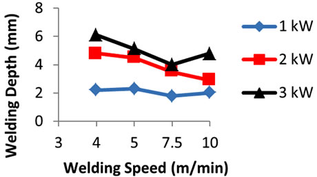
Figure 8. Influence of welding speed on the welding depth of RLW of stainless steel 1.4301 with different laser powers, the focal length is 500 mm [36].
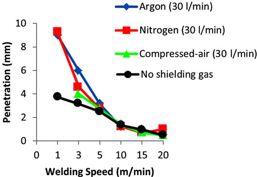
Figure 9. Influence of shielding gas on welding depth and welding speed of RLW of steel with an 8-kW fiber laser [15].

Figure 10. Influence of focal positions on the seam depth and width of remote fiber laser welding [15].
4. Conclusion
This paper studied remote laser welding with fiber lasers. Remote fiber laser welding is a versatile technology with a promising future. The process has been adopted by the automotive industry due to its advantageous characteristics, such as high productivity, high flexibility, and low operational costs. The scanner system is one of the most important requirements for remote fiber laser welding. However, to make a sound weld, a number of process parameters, such as beam quality, laser power, welding speed, shielding gas supply, and focal position have to be taken into account in remote laser welding.
REFERENCES
- G. Tsoukantas, A. Stournaras and G. Chryssolouris, “Experimental Investigation of Remote Laser Welding with CO2 and Nd: YAG Laser-Based Systems,” Journal of Laser Applications, Vol. 20, No. 1, 2008, pp. 50-58. doi:10.2351/1.2832400
- J. Macken, “Remote Laser Welding,” Proceeding of the International Body Engineering Conference, Advanced Technologies and Processes, Warren-MI, 1996, pp. 11- 15.
- J. Cann, “A Look at the Remote Laser Beam Welding,” Welding Journal, Vol. 84, No. 8, 2005, pp. 34-37.
- M. Grupp, T. Seefeld and F. Vollertsen, “Laser Beam Welding with Scanner,” Proceedings of the Second International WLT-Conference on Lasers in Manufacturing, Munich, 2003, pp. 211-222.
- G. Tsoukantas and G. Chryssolouris, “Theoretical and Experimental Analysis of the Remote Welding Process on Thin, Lap-Joined AISI 304 Sheets,” International Journal of Advanced Manufacturing Technology, Vol. 35, No. 9- 10, 2008, pp. 880-894. doi:10.1007/s00170-006-0767-0
- F. Oefele, J. Musiol and M. F. Zaeh, “Influence of Remote-Laser-Welding Parameters for an 8 kW Fibre Laser on Seam Quality of Steels,” The 27th International Congress on Applications of Lasers & Electro-Optic (ICALEO 2008), Temecula, 2008, pp. 399-405.
- C. Kim, J. Kim, H. Lim and J. Kim, “Investigation of Laser Remote Welding Using Disc Laser,” Journal of Materials Processing Technology, Vo. 201, No. 1-3, 2008, pp. 521- 525. doi:10.1016/j.jmatprotec.2007.11.165
- S. Kenji, Y. Motomichi, M. Kenta, Y. Daisuke, K. Yusuke and O. Takuya, “Development of Remote Laser Welding Method Using Long Focal-Distance Lens for Automobile Galvannealed Steel,” Transactions of the Japan Welding Society, Vol. 27, No. 2, 2009, pp. 60-63. doi:10.2207/qjjws.27.60s
- K. Klingbeil, “What You Need to Know about Remote Laser Welding: A Look at How Remote Laser Welding Works and How It Can Be Applied to Your Manufacturing Process,” Welding Journal, Vol. 85, No. 8, 2006, pp. 44-46.
- M. P. Vänskä, “Implementing the Modern Fiber Laser Technology for Welding of Stainless Tubular Products,” Master’s Thesis, Lappeenranta University of Technology, Lappeenranta, 2009.
- M. F. Zaeh, J. Moesl, J. Musiol and F. Oefele, “Material Processing with Remote Technology—Revolution or Evolution?” Physics Procedia, Vol. 5, 2010, pp. 19-33. doi:10.1016/j.phpro.2010.08.119
- T. Heston, “Remote Laser Beam Welding Shows Potential in the Body Shop,” Welding Journal, Vol. 79, No. 6, 2000, pp. 39-42.
- M. Bemenek, “Technology Report: Welding from a Distance,” Industrial Laser Solutions, Vol. 21, No. 3, 2006, pp. 19-23.
- E. Beyer, A. Klotzbach, V. Fleischer and L. Morgenthal, “Nd: YAG-Remote Welding with Robots,” Proceedings of the Second International WLT-Conference on Lasers in Manufacturing, Munich, 2003, pp. 367-373.
- M. F. Zaeh, U. Munzert and F. Oefele, “Robot Based Remote-Laser-Welding without Scanner Optics,” Proceedings of the Fourth International WLT-Conference on Lasers in Manufacturing, Munich, 2007, pp. 1-8.
- D. A. Sabo, “The Evolution of Scanners for Remote Welding Applications: The Rise of Beam Quality Leads to Proliferation of Remote Welding Applications,” 2007. http://www.thefabricator.com/article/lasercutting/the-evolution-of-scanners-for-remote-welding-applications
- M. Bea, R. Brockmann and D. Havrilla, “Remote Laser Welding in Automotive Production,” Industrial Laser Solutions, Vol. 26, No. 5, 2011, pp. 8-12.
- M. F. Zaeh, J. Musiol and J. Moesl, “Methodical Qualification of Scanner Systems for Remote Laser Cutting,” Proceedings of the 29th International Congress on Applications of Laser & Electro-Optics, Orlando, 26-30 September 2010, pp. 362-370.
- Scansonic, “Remote Laser Welding—Adaptive,” 2011. http://www.scansonic.de/files/downloads/scansonic_rlw-a_datasheet_v2.0_en.pdf
- L. Quintino, A. Costa, R. Miranda, D. Yapp, V. Kumar and C. J. Kong, “Welding with High Power Fiber Laser— A Preliminary Study,” Materials and Design, Vol. 28, No. 4, 2007, pp. 1231-1237. doi:10.1016/j.matdes.2006.01.009
- Y. Kawahito, M. Mizutani and S. Katayama, “Investigation of High-Power Fiber Laser Welding Phenomena of Stainless Steel,” Transactions of JWRI, Vol. 36, No. 2, 2007, pp. 11-15.
- A. Kratky, D. Schuöcker and G. Liedl, “Processing with kW Fiber Lasers—Advantages and Limits,” XVII International Symposium on Gas Flow, Chemical Lasers and High-Power Lasers, 21 April 2009. doi:10.1117/12.816655
- M. Lütke, A. Mahrle, T. Himmer, L. Morgenthal and E. Beyer, “Remote Cutting—A Smart Solution Using the Advantages of High Brightness Lasers,” Proceedings of the International Congress on Applications of Lasers & Electro-Optics, Temecula, 20-23 October 2008, pp. 695- 702.
- Duggan Manufacturing, “New Process Development Facility for Remote Fiber Laser Welding,” 2010. http://weldingdesign.com/equipment-automation/news/process-development-facility-remote-fiber-laser-0313/
- P. Anthony, “The Reality of Remote Laser Welding,” Industrial Laser Solutions, Vol. 19, No. 2, 2004, pp. 9-11.
- A. Korinth and J. Cann, “Remote Welding Impacts on Auto Manufacture,” Industrial Laser Solutions, Vol. 20, No. 5, 2005, pp. 26-31.
- J. Hatwig, G. Reinhart and M. F. Zaeh, “Automated Task Planning for Industrial Robots and Laser Scanners for Remote Laser Beam Welding and Cutting,” Production Engineering: Research and Development, Vol. 4, No. 4, 2010, pp. 327-332. doi:10.1007/s11740-010-0252-3
- K. Mori, T. Tarui, T. Hasegawa and N. Yoshikawa, “Remote Laser Welding Applications for Car Bodies,” Welding International, Vol. 24, No. 10, 2010, pp. 758-763. doi:10.1080/09507111003655283
- L. X. Zhang, L. Wu, H. M. Gao and G. J. Zhang, “Agent- Based Modeling and Control of Remote Robotic Welding System,” Robotic Welding, Intelligence and Automation, Vol. 362, 2007, pp. 187-194. doi:10.1007/978-3-540-73374-4_21
- K. Krastel, “Remote Laser Welding in Industrial Applications,” 2006. http://www.photonics.com/Article.aspx?AID=26648
- G. Verhaeghe, “Remote Laser Welding for Automotive Seat Production,” Industrial Laser Solutions, Vol. 27, No. 3, 2012, pp. 6- 11.
- J. Duong, “Qualification of the Convection Mode Laser Beam Welding Process,” Master’s Thesis, Lappeenranta University of Technology, Lappeenranta, 2010.
- W. M. Steen and J. Mazumder, “Laser Material Processing,” 4th Edition, Springer, London, 2010. doi:10.1007/978-1-84996-062-5
- R. L. O’Brien, “Laser Beam Welding,” In: R. L. O’Brien, Ed., Welding Handbook—Welding Processes, 8th Edition, Vol. 2, American Welding Society, Miami, 1991, pp. 713-738.
- S. Katayama, S. Oiwa, N. Matsumoto, M. Mizutani and Y. Kawahito, “Fundamentals of Fiber Laser Remote Welding and Deep Penetration Welding,” European Quantum Electronics Conference on Lasers and Electro-Optics, Munich, 14- 19 June 2009, p. 1.
- L. Hartwig, R. Ebert, S. Kloetzer, S. Weinhold, J. Drechsel, F. Peuckert, J. Schille and H. Exner, “Material Processing with a 3 kW Single Mode Fiber Laser,” Journal of Laser Micro/Nanoengineering, Vol. 5, No. 2, 2010, pp. 128-133.
- F. Oefele, U. Munzert, M. F. Zaeh, “Remote-Laser-Welding with an 8 kW Fibre Laser,” Proceedings of the Laser Assisted Net Shape Engineering, Erlangen, 2007, pp. 183- 196.
- M. J. Song, B. H. Jung, M. Y. Lee and J. Suh, “Laser Welding Automobile Bumpers: Remote Welding System with Shielding Gas,” Industrial Laser Solutions, Vol. 23, No. 4, 2008, pp. 17-20.
- C. Dawes, “Laser Welding: A Practical Guide,” Abington Publishing, Cambridge, 1992. doi:10.1533/9781845698843
- C. Wandera, “Laser Cutting of Austenitic Stainless Steel with a High Quality Laser Beam,” Master’s Thesis (In Finnish), Lappeenranta University of Technology, Lappeenranta, 2006.