Engineering
Vol.5 No.1A(2013), Article ID:27319,8 pages DOI:10.4236/eng.2013.51A017
Macroscopic Structural Analysis on a 10 kW Class Lab-Scale Process Heat Exchanger Prototype under a High-Temperature Gas Loop Condition
1Korea Atomic Energy Research Institute, VHTR Technology Development Group, Daejeon, South Korea
2AD Solution, Daejeon, South Korea
Email: *knsong@kaeri.re.kr
Received September 28, 2012; revised October 27, 2012; accepted November 10, 2012
Keywords: Process Heat Exchanger; Very High Temperature Reactor; High-Temperature Structural Analysis; Nuclear Hydrogen
ABSTRACT
A PHE (Process Heat Exchanger) is a key component in transferring high-temperature heat generated from a VHTR (Very High Temperature Reactor) to a chemical reaction for the massive production of hydrogen. Last year, a 10 kW class lab-scale PHE prototype made of Hastelloy-X was manufactured at the Korea Atomic Energy Research Institute (KAERI), and a performance test of the PHE prototype is currently underway in a small-scale nitrogen gas loop at KAERI. The PHE prototype is composed of two kinds of flow plates: grooves 1.0 mm in diameter machined into the flow plate for the primary coolant, and waved channels bent into the flow plate for the secondary coolant. Inside the 10 kW class lab-scale PHE prototype, twenty flow plates for the primary and secondary coolants are stacked in turn. In this study, to understand the macroscopic structural behavior of the PHE prototype under the steady-state operating condition of the gas loop, high-temperature structural analyses on the 10 kW class lab-scale PHE prototype were performed for two extreme cases: in the event of contacting the flow plates together, and when not contacting them. The analysis results for the extreme cases were also compared.
1. Introduction
Hydrogen is considered a promising future energy solution, as it is clean, abundant, and storable, and has highenergy density. One of the major challenges in establishing a hydrogen economy is how to produce massive quantities of hydrogen in a clean, safe, and economical way. Among the various hydrogen production methods, nuclear hydrogen production has garnering attention worldwide since it can produce hydrogen, a promising energy carrier, without environmental burden. Research demonstrating the massive production of hydrogen using a VHTR (Very High Temperature Reactor) designed for operation at up to 950˚C has been actively carried out worldwide, including in the USA, Japan, France, and the Republic of Korea (ROK) [1-3].
A Sulfur-Iodine (SI) process that requires high temperature energy is well known as a feasible technology to produce hydrogen from water [4]. The SI process for hydrogen production requires sufficient heat that can be supplied by a nuclear reactor. A VHTR should be used as a high temperature energy source. The nuclear hydrogen program in the ROK has been strongly considering for producing hydrogen by employing an SI water-splitting hydrogen production process as shown in Figure 1 [5,6]. An intermediate loop that transports the nuclear heat to the hydrogen production process is necessitated for a nuclear hydrogen program. In the intermediate loop, unlike the hot gas duct, which provides a route of hightemperature gas from the nuclear reactor to the intermediate heat exchanger, the PHE (Process Heat Exchanger) is a component that utilizes the nuclear heat from the nuclear reactor to provide for hydrogen production. PHE is used in several processes such as nuclear steam reforming, nuclear methanol, nuclear steel, nuclear oil refineries, and nuclear steam [1]. The PHE of the SO3 decomposer, which generates process gases such as H2O, O2, SO2, and SO3 at a very high temperature, is a key component in the nuclear hydrogen program in the ROK.
Recently, KAERI (Korea Atomic Energy Research Institute) established a small-scale nitrogen gas loop for a performance test of VHTR components, and manufactured a 10 kW class lab-scale PHE prototype made of Hastelloy-X. The 10 kW class lab-scale PHE prototype is composed of two kinds of flow plates; grooves 1.0 mm in
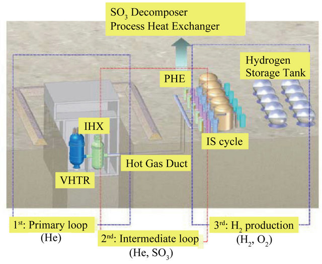
Figure 1. Nuclear hydrogen system.
diameter machined into the flow plate for the primary coolant, and waved channels bent into the flow plate for the secondary coolant. Inside the 10 kW class lab-scale PHE prototype, twenty flow plates for the primary and secondary coolants are stacked in turn. A performance test of the 10 kW class lab-scale PHE prototype is underway in the small-scale gas loop at KAERI, as shown in Figure 2. In reality, the flow plates inside the 10 kW class lab-scale PHE prototype were not metallurgically joined with each other. During the performance test of the 10 kW class lab-scale PHE prototype, the flow plates might not make contact with each other.
In this study, to understand the macroscopic structural behavior of the PHE prototype under a steady-state operating condition of the gas loop, high-temperature structural analyses on the 10 kW class lab-scale PHE prototype were performed for two extreme cases: in the event of the flow plates making contacting with each other, and cases in which they do not make contact. The analysis results for the extreme cases were also compared.
2. Finite Element Modeling
A schematic view of the inside of the 10 kW class labscale PHE prototype is illustrated in Figure 3. The PHE prototype is designed as a hybrid concept to meet the design pressure requirements between a nuclear system and hydrogen production system [7]. That is to say, the hot nitrogen gas channel has a compact semicircular shape, similar to a printed circuit heat exchanger, and is designed to withstand the high pressure difference between loops, while the sulfuric acid gas channel has a plate fin shape with sufficient space to install and replace the catalysts for sulfur trioxide decomposition as shown in Figure 4.
All parts of the 10 kW class lab-scale PHE prototype
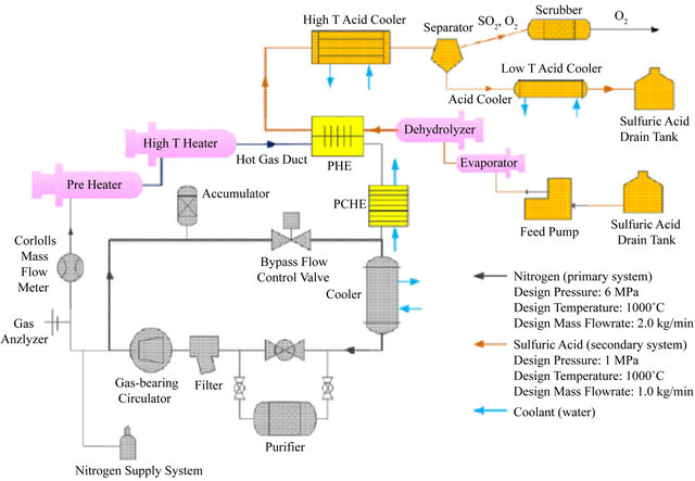
Figure 2. Small-scale nitrogen gas loop.
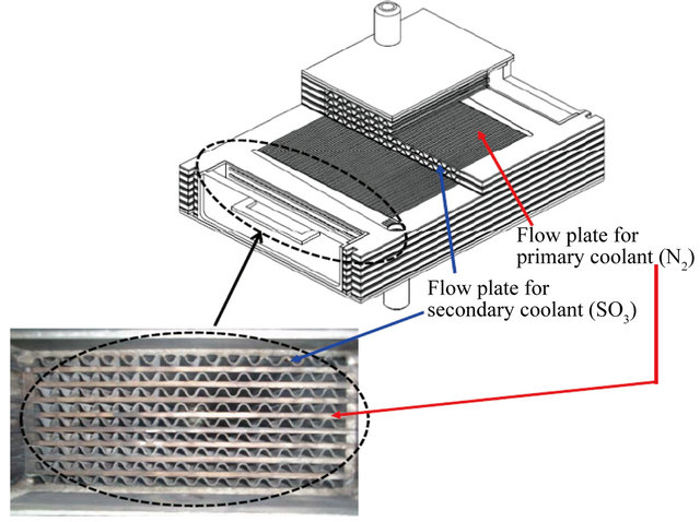
Figure 3. Inside of a lab-scale PHE prototype.
 (a) (b)
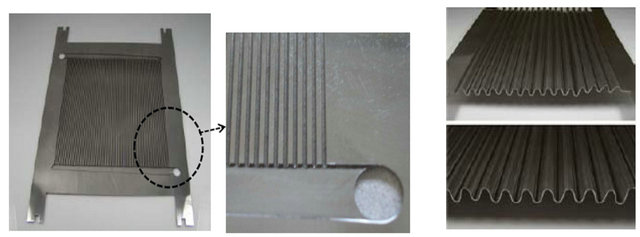
Figure 4. Flow plates of a lab-scale PHE prototype. (a) Primary flow plate; (b) Secondary flow plate.
are made of Hastelloy-X of high-temperature alloy. Grooves 1.0 mm in diameter are machined into the flow plate for the primary coolant (nitrogen gas). Waved channels are bent into the flow plate for the secondary coolant (SO3 gas). Twenty flow plates for the primary and secondary coolants are stacked in turn, and are bonded along the edge of the flow plate using a solid-state diffusion bonding method. After stacking and bonding the flow plates, the outside of the PHE is covered with a Hastelloy-X plate 3.0 mm thick, and is welded along its edges using TIG welding.
Figure 5 shows the overall dimensions and each part of the 10 kW class lab-scale PHE prototype from a 3-D CAD modeling. Figure 6 shows the set-up of the PHE prototype in a small-scale nitrogen gas loop. Based on Figure 6, FE modeling using commercial code I-DEAS was carried out. For the sake of simplicity and an understanding of the overall structural behavior of the PHE prototype, the FE model was formulated with linear solid elements including brick elements, wedge elements, and tetrahedron elements. The structural FE model of the PHE prototype was formulated using 870,696 brick elements.
For the FE model, the inflow/outflows of the primary and secondary coolants are shown in Figures 7 and 8 [8]. The inflow of the primary coolant into the PHE prototype and the outflow of the primary coolant from the PHE
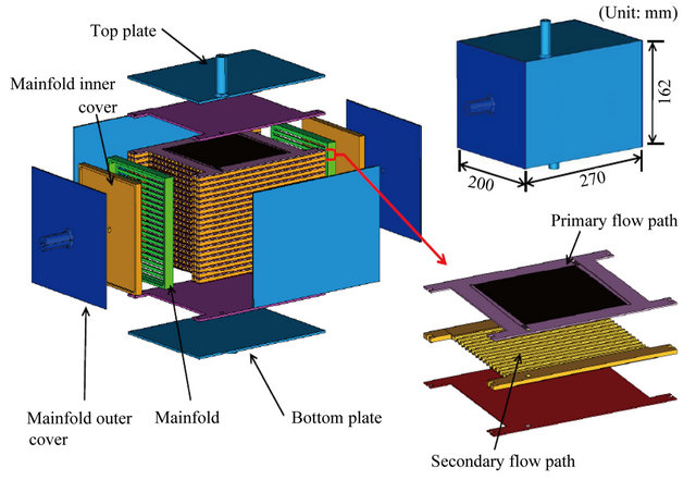
Figure 5. Parts of a 10 kW lab-scale PHE prototype.
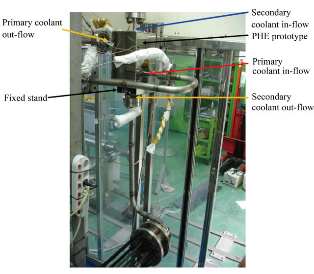
Figure 6. Set-up of a 10 kW class lab-scale PHE prototype in a small-scale nitrogen gas loop.
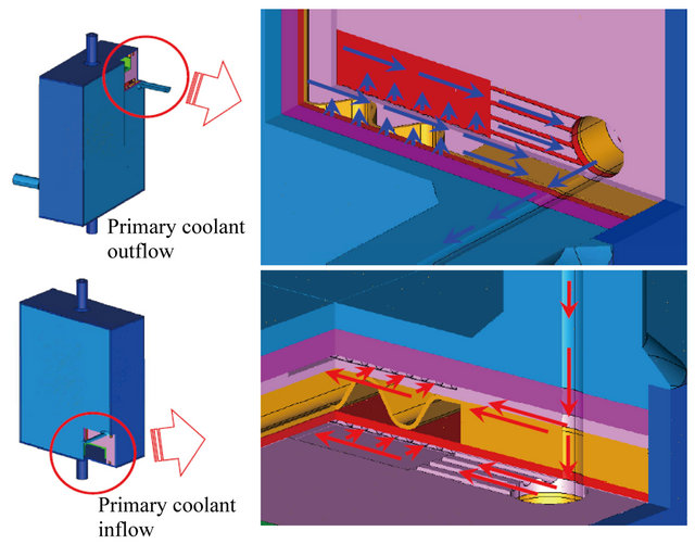
Figure 7. Inflow/outflow of the primary coolant.
prototype, after the heat is transferred to the secondary coolant, are shown in Figure 7. The inflow of the secon-
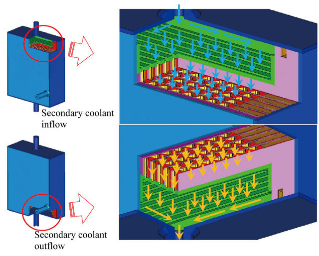
Figure 8. Inflow/outflow of the secondary coolant.
dary coolant into the PHE prototype and the outflow of the secondary coolant from the PHE prototype, after the heat is received from the primary coolant, are shown in Figure 8.
3. Analysis
3.1. Thermal Analysis
Figures 9 and 10 show the input data of the primary/ secondary flow plates for a thermal analysis under a gas loop test condition of 850˚C in the event that flow plates contact and do not contact, respectively. Table 1 shows the material properties of Hastelloy-X alloy extracted from a website [9]. Based on the input data shown in Figures 9 and 10, thermal analyses on the 10 kW labscale PHE prototype has been carried out using I-DEAS/ TMG ver. 6.1 [10].
Table 1. Material properties of Hastelloy-X.
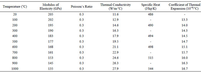
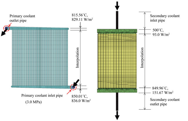
Figure 9. Thermal input of flow plates for a thermal analysis in the event of flow plates contacting each other.
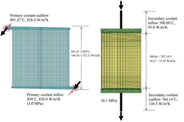
Figure 10. Thermal input of flow plates for a thermal analysis in the event of flow plates not contacting each other.
Figures 11 and 12 show the thermal analysis results of the PHE prototype inside/outside under the test condition of a small-scale nitrogen gas loop. According to Figures 11 and 12, the temperature distributions are nearly symmetrical along the vertical axis. In addition, the maximum temperature of the outside is about 836.26˚C when the flow plates make contact with each other, while the maximum temperature of the outside is about 748.61˚C when the flow plates do not make contact.
3.2. Boundary Conditions for Structural Analysis
Based on the thermal analysis results shown in Figures 11 and 12, high-temperature elastic/elastic-plastic structural analyses using ABAQUS Ver. 6.8 [11] were performed by imposing displacement constraint conditions at each end of the primary/secondary flow pipelines as shown in Figure 13, considering the pipeline stiffness of the small-scale nitrogen gas loop [8,12,13]. These conditions were established in previous work [8]. The bilinear stress-strain curve of Hastelloy-X for an elastic-plastic structural analysis extracted from a website [9] is shown in Figure 14.
According to the test condition of the small-scale nitrogen gas loop, the in/outflow pressures for the primary and secondary coolant are 3.0 MPa and 0.1 MPa, respectively.
3.3. Structural Analysis Results
Figure 15 shows the elastic stress contours at the pressure boundary of the PHE prototype. A maximum local
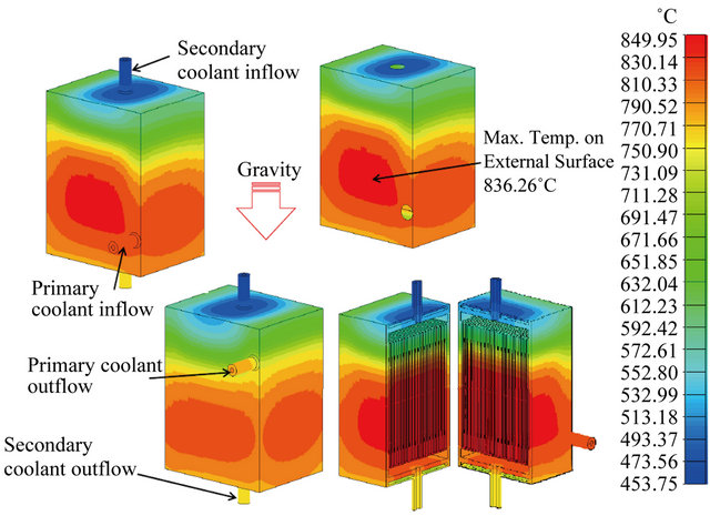
Figure 11. Temperature contours of the PHE outside in the event of flow plates contacting each other.
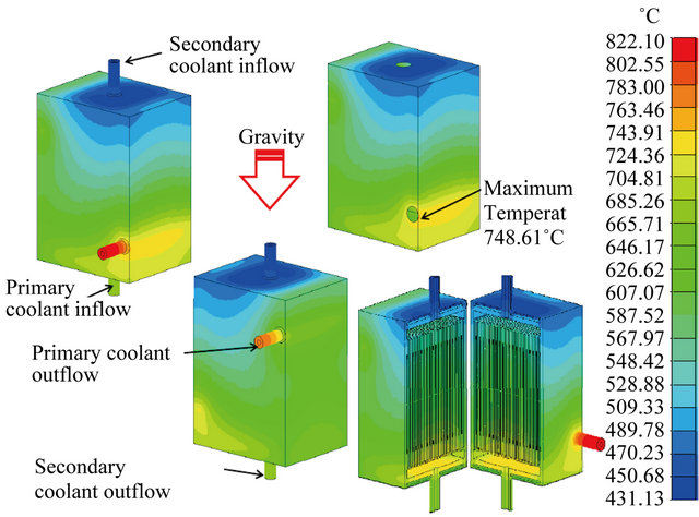
Figure 12. Temperature contours of the PHE outside in the event of flow plates not contacting each other.
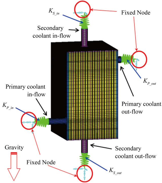
Figure 13. Boundary conditions for a structural analysis.
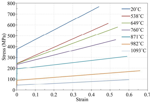
Figure 14. Bilinear stress-strain curve of Hastelloy-X.
stress of 331.23 MPa occurs around the edge between the top and side plates, which exceeds the yield stress of the material (238.0 MPa at 744.46˚C) by 39.17%. Figure 16 shows the elastic-plastic stress contours at the pressure boundary of the PHE prototype. According to Figure 16, a maximum local stress of 263.60 MPa also occurs around the edge between the top and side plates, which exceeds the yield stress of the material (238.12 MPa at 742.23˚C) by 10.70%. The maximum local stress that occurs around the edge in the FE model will decrease to a certain degree when considering the chamfered edges, since the edges of the PHE prototype are chamfered realistically.
Figure 17 shows the elastic stress contours at the pressure boundary of the PHE prototype. The maximum local stress of 272.96 MPa exceeds the yield stress of the material (243.44 MPa at 657.93˚C) by 12.13%. Figure 18 shows the elastic-plastic stress contours at the pressure boundary of the PHE prototype. According to Figure 18, the maximum local stress of 253.75 MPa also exceeds the yield stress of the material (242.20 MPa at 677.55˚C) by 4.77%.
To understand the macroscopic structural behavior of a PHE prototype under a steady-state operating condition of a gas loop, high-temperature structural analyses on a 10 kW class lab-scale PHE prototype were performed for two extreme cases: in the event of contacting the flow plates with each other, and when not contacting them. The maximum stress level of the PHE prototype under real test conditions seems to be within two extreme cases. The maximum local stresses, peak stresses, occur around the edges in the FE models, as shown in Figures 15-18. However, the chamfering (or rounding) along the edge of the prototype is not considered in the FE model for the
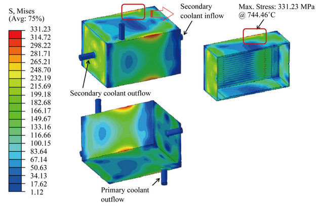
Figure 15. Overall stress contours from an elastic analysis for flow plates contacting each other.
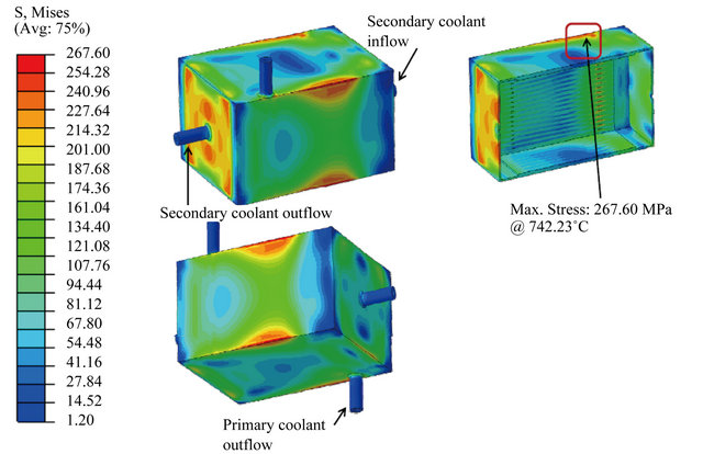
Figure 16. Overall stress contours from an elastic-plastic analysis for flow plates contacting each other.
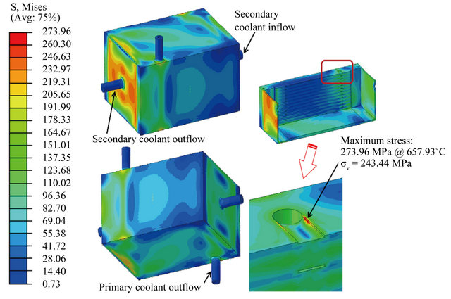
Figure 17. Overall stress contours from an elastic analysis for flow plates not contacting each other.
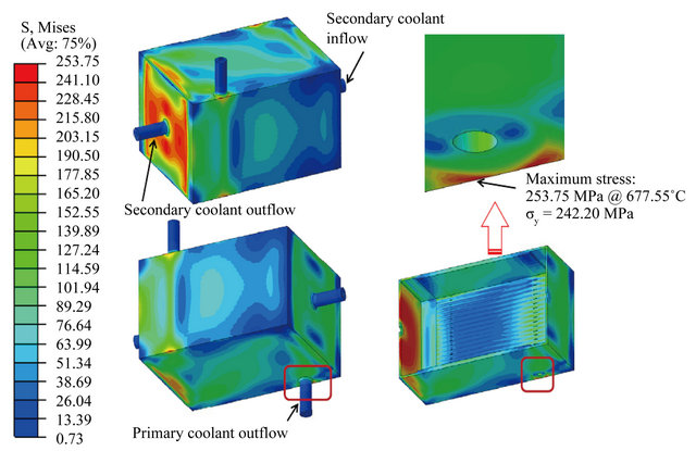
Figure 18. Overall stress contours from an elastic-plastic analysis for flow plates not contacting each other.
sake of simplicity. Thus, the peak stress occurring around the edges in the FE model will decrease to some extent when considering the chamfered edges, since the edges of the prototype are in reality chamfered. Therefore, the high-temperature structural integrity of the PHE prototype seems to be guaranteed in the gas loop test condition.
4. Conclusion
To investigate the macroscopic structural behavior of a PHE prototype under a steady-state operating condition of a gas loop, and as a precedent study before performing a performance test in a gas loop, high-temperature structural analyses on the 10 kW class lab-scale PHE prototype were performed for two extreme cases: in the event of the flow plates contacting together and not contacting together. As a result of the analyses, the structural integrity of the PHE prototype under real test conditions seems to be guaranteed, considering the chamfering effect on the edge of the PHE prototype.
REFERENCES
- W. J. Lee, Y. W. Kim and J. H. Chang, “Perspectives of Nuclear Heat and Hydrogen,” Nuclear Engineering and Technology, Vol. 41, No. 4, 2009, pp. 413-426. doi:10.5516/NET.2009.41.4.413
- US DOE, “Financial Assistance Funding Opportunity Announcement,” Next Generation Nuclear Plant ProgramGas Cooled, US DOE Idaho Operation Office, 2009.
- AREVA, “NGNP with Hydrogen Production Pre-Conceptual Design Studies Report,” Doc. No. 1209052076- 000, AREVA, Seattle, 2007.
- L. C. Brown, G. E. Besenbruch, R. D. Lentsch, K. R. Schultz, J. F. Funk, P. S. Pickard, A. C. Marshall and S. K. Showalter, “High Efficiency Generation of Hydrogen Using Nuclear Power,” GA-A24285, General Atomics, San Diego, 2003.
- J. H. Chang, et al., “A Study of a Nuclear Hydrogen Production Demonstration Plant,” Nuclear Engineering and Technology, Vol. 39, No. 2, 2007, pp. 111-122. doi:10.5516/NET.2007.39.2.111
- Y. J. Shin, et al., “A Dynamic Simulation of the Sulfuric Acid Decomposion Process in a Sulfur-Iodine Nuclear Hydrogen Production Plant,” Nuclear Engineering and Technology, Vol. 41, No. 6, 2009, pp. 831-840. doi:10.5516/NET.2009.41.6.831
- Y. W. Kim, “High Temprature and High Pressure Corrosion Resistant Process Heat Exchanger for a Nuclear Hydrogen Production System,” Korea Patent No.0877574, 2008.
- K. N. Song, S. D. Hong and H. Y. Park, “High-Temperature Structural Analysis of a Small-Scale PHE Prototype under the Test Condition of a Small-Scale Gas Loop,” Science and Technology of Nuclear Installations, Vol. 2012, 2012, Article ID: 312080. doi:10.1155/2012/312080
- HAYNES International, “Hastelloy-X Alloy,” 2012. http://www.haynesintl.com/pdf/h3009.pdf
- “Siemens PLM Software I-DEAS/TMG User Manual Version 6.1,” Plano, 2009.
- “Dassault Systemes Simulia ABAQUS User Manual Version 6.8,” Waltham, 2009.
- K. N. Song, S. D. Hong and H. Y. Park, “High-Temperature Structural Analysis on a Medium-Scale Process Heat Exchanger,” Transactions of the Korean Society of Mechanical Engineers-A, Vol. 36, No. 10, 2012, in Press.
- K. N. Song, S. D. Hong and H. Y. Park, “High-Temperature Structural Analysis of a Small-Scale Process Heat Exchanger (III),” Transactions of the Korean Society of Mechanical Engineers-A, Vol. 35, No. 2, 2011, pp. 191-200. doi:10.3795/KSME-A.2011.35.2.191
NOTES
*Corresponding author.