Engineering
Vol. 4 No. 7 (2012) , Article ID: 20542 , 4 pages DOI:10.4236/eng.2012.47045
3D Display System Based on Digital Holography —Application in Making Cartoon Holography
National Institute for Standards: Length and Engineering Precision (NIS), Giza, Egypt
Email: niveen_farid@hotmail.com
Received January 20, 2012; revised February 27, 2012; accepted March 10, 2012
Keywords: 3D Display Model; Fourier Transformation; Cartoon Holography
ABSTRACT
Holography is an interesting tool in creating real objects and scenes which can be projected anywhere with accurate details and depth impression. It is also found to be more attractive to the artists than other alternatives. For that reason, digital holography is being used as a display technology in cartoon movies. Since this application is dependent on the performance and the simplicity of the available display technology, it becomes very useful to improve the display technique in order to become fast, simple, and attractive by being combined with computer graphical effects. This paper discusses a simulation of a digital holographic model as a three dimensional (3D) display system and its application in making cartoon holography.
1. Introduction
Some previous work discussed the creation of a threedimensional (3D) effect for an image by rotating the twodimensional (2D) one on a computer screen in order to add the required sense of image depth depending on image processing techniques. In the meanwhile, many types of the display technology interact with our activities and enable us to see 3D images in virtual reality [1,2]. Among these types, the digital holography is a simple fast technology which provides the depth impression and the desired size to the reconstructed image without need to complicated optical systems which require expensive receivers, special developing solutions, high quality optcal components in addition to a high stable environment. Moreover, to produce an optical hologram, the object needs to be illuminated with a laser beam and the scattered beams interfere with the reference ones, then the interference patterns are recorded. The 3D object image is then reconstructed from the recorded optical hologram using a special constructing system. In case of existence of air currents, sounds or temperature changes, the recording will blur and become useless.
Digital models which are simulated by computer are increasingly used to carry out the whole process chain of making the hologram and reconstructing the 3D image. The generated fringe patterns are similar to those resulted optically from the interference of the wavefront from the reference and the object beams at the photographic plate or even captured by the CCD camera. The digital holographic technique needs a set of sufficient data to be added to the computer software in order to generate a synthetic hologram for displaying the 3D scene. The advantage of this method is the absence of any optical requirements for recording and reconstruction. Moreover, it can be used to reconstruct virtual objects according to the proposed algorithm for calculating the hologram and reconstructing the 3D cartoon images. The reconstructed image can be then combined with graphical effects to make cartoon holography in the desired viewing scene to become attractive to people.
2. Digital Holographic Model
Several holographic techniques presented in [3-9] introduce different methods to record the hologram and reconstruct the 3D image, such as:
• Recording multi images for the object at different view angles, and combining the different holograms to display the 3D image from different direction.
• Arranging the Fourier holograms in a circular synthetic hologram to achieve 360 degrees of the scene.
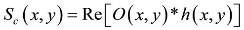
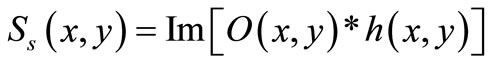
To create a 3D image using digital holographic system, the 2D image is handled by the Fourier transformation, optical transfer function, and inverse Fourier transformation in order to create the cartoon hologram and finally reconstruct the 3D cartoon image with the required depth sense. In the proposed model, The object is considered to be represented by one plane xy-plane with a plan intensity distribution described by O(x, y), then the scattered field in the spatial domain for both cos and sin components is described by
 (1)
(1)
 (2)
(2)
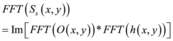
where h(x,y) is the point spread function. Taking the Fourier transform for both equations:
 (3)
(3)
 (4)
(4)
 relates the output quantity to the input quantity in the frequency domain, and defines the optical transfer function
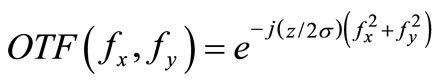
  which describes the spatial variation as a function of the spatial frequency. Then the wavefront (to be reconstructed) is the superposition of the Fourier transform of the object modified by a phase factor. According to [10], the optical transfer function required to record a hologram in the Fourier domain is:
 (5)
(5)
where  is the wave number, λ is the wavelength,
  is the distance at which Fresnel diffraction is simulated,
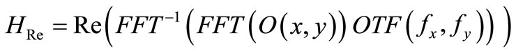
  are the spatial frequencies. Both real and imaginary holograms are obtained by the inverse Fourier transformation of the scattered wave modified by the optical transfer function:
 (7)
(7)
 (8)
(8)
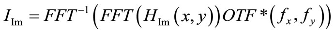
The reconstructed images are:
 (9)
(9)
 (10)
(10)
The model is simulated on the computer as follows:
private void ReadImage()
{ int i, j;
GreyImage = new int[Width, Height];
Bitmap image = Obj;
BitmapData bitmapData1 =
image.LockBits(new Rectangle(0, 0, image.Width,
image.Height), ImageLockMode.ReadOnly,
PixelFormat.Format32bppArgb);
unsafe
{ byte* imagePointer1 =
(byte*)bitmapData1.Scan0;
for (i = 0; i < bitmapData1.Height; i++)
{ for (j = 0; j < bitmapData1.Width; j++)
{ GreyImage[j, i] =
(int)((imagePointer1[0] +
imagePointer1[1] +
imagePointer1[2]) / 3.0);
imagePointer1 += 4; }
imagePointer1 +=
bitmapData1.Stride - (bitmapData1.Width * 4);} }
image.UnlockBits(bitmapData1);
return; }
/// Calculate Fast Fourier Transform of Input Image
public Complex[,] ForwardFFT()
{ int i, j;
Fourier = new Complex[Width, Height];
Output = new Complex[Width, Height];
for (i = 0; i <= Width − 1; i++)
for (j = 0; j <= Height − 1; j++)
{ Fourier[i, j].real =
(double)GreyImage[i, j];
Fourier[i, j].imag = 0; }
Output = FFT2D(Fourier, nx, ny, 1);
return Output; }
public void GetHologram()
{ for (int r = 1; r <= Cols; r++)
{ Fx = −12.8;
for (int c = 1; c <= Rows; c++)
{OTF[r, c].real = 0;
OTF[r, c].imag = Math.Exp(-1* imaginary_J
*(z/(2*sigma))*(Fx*Fx+Fy*Fy));
Fx = Fx + 0.1;}
Fy = Fy + 0.1;}
int i = 0;
int j = 0;
ImgFFT = new FFT(InputImage);
ImgFourier = ImgFFT.ForwardFFT();
public void FFTShift()
{ int i, j;
FFTShifted = new Complex[nx, ny];
for (i = 0; i <= (nx / 2) − 1; i++)
for (j = 0; j <= (ny / 2) − 1; j++)
{ FFTShifted[i + (nx / 2), j + (ny / 2)] = Output[i, j];
FFTShifted[i, j] = Output[i + (nx / 2), j + (ny / 2)];
FFTShifted[i + (nx / 2), j] = Output[i, j + (ny / 2)];
FFTShifted[i, j + (nx / 2)] = Output[i + (nx / 2), j];}
return; }
//Calculate hologram in Fourier domain
ImgFourier = MatrixMultiply(ImgFourier, OTF);
InvImgFourier = ImgFFT.InverseFFT(ImgFourier);
//Calculate Real and Imaginary holograms
HRe = MatrixMultiply(RealFourier, OTF*);
HIm = MatrixMultiply(ImaginaryFourier, OTF*);
//Digital image reconstruction
IRe = ImgFFT.InverseFFT(HRe);
IIm = ImgFFT.InverseFFT(HIm);
Figure 1 shows the steps of implementation of the proposed model.
3. Cartoon Images Created by the Model
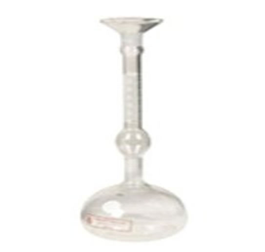
The simulated holographic system is applied to object 2D images to create the 3D images with depth impression without need to any additional technical equipment. Some of the 3D reconstructed images are combined with backgrounds to give attractive cartoon scenes. The model is simple and not limited to the kind of object of interest since any image can be read as an input by the software. The created images are seen in Figure 2.
 (a)
(a)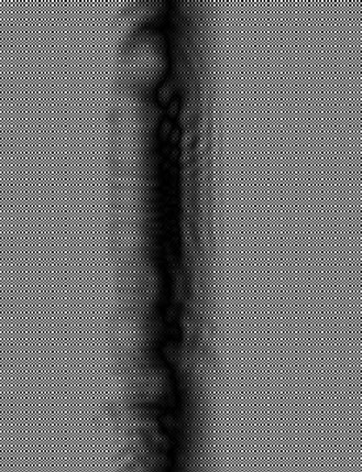 (b)
(b)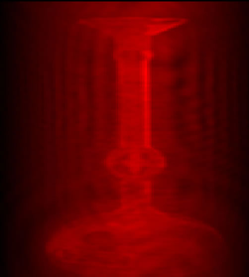 (c)
(c)
Figure 1. (a) Image read by the model; (b) Sin and Cos holograms; and (c) Reconstruction of the hologram.
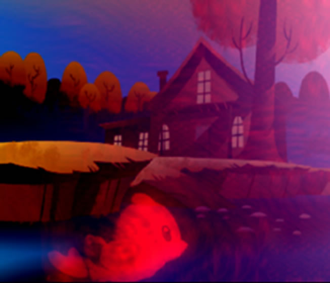

Figure 2. Cartoon images formed by the simulated holographic model.
4. Conclusion
A digital display system is simulated to be capable of displaying 3-D images having all the relevant information and visual properties of the scenes to be viewed. The simulated model is a fast simple display technique without need to install optical system or even real objects. The created 3D cartoon images are viewed with depth impression and are scaled to a desired size. It is also possible to combine the constructed images with some graphical effects to be more enjoyable.
REFERENCES
- J. Y. Son, B. Javidi and K. D. Kwack, “Methods for Displaying Three-Dimensional Images,” Proceedings of IEEE, Vol. 94, No. 3, 2006, pp. 502-523. doi:10.1109/JPROC.2006.870686
- C. Slinger, C. Cameron and M. Stanley, “ComputerGenerated Holography as a Generic Display Technology,” Computer, Vol. 38, No. 8, 2005, pp. 46-53. doi:10.1109/MC.2005.260
- L. Yaroslavsky and N. Merzlyakov, “Methods of Digital Holography,” Consultance Bureau, New York, 1980.
- L. B. Lesem, P. M. Hirsch and J. A. Jordan Jr., “Computer Synthesis of Holograms for 3-D Display,” Communications of the ACM, Vol. 11, 1968, pp. 661-674. doi:10.1145/364096.364111
- L. B. Lesem, P. M. Hirsch and J. A. Jordan, “The Kinοform: A New Wavefront Reconstruction Device,” IBM Journal of Research and Development (IBM), Vol. 13, No. 2, 1969, pp. 150-155. doi:10.1147/rd.132.0150
- W. H. Lee, “Sampled Fourier Transform Hologram Generated by Computer,” Applied Optics, Vol. 9, 1970, pp. 639-643. doi:10.1364/AO.9.000639
- D. Leseberg and O. Bryngdahl, “Computer-Generated Rainbow Holograms,” Applied Optics, Vol. 23, No. 14, 1984, pp. 2441-2447. doi:10.1364/AO.23.002441
- F. Wyrowski, R. Hauck and O. Bryngdahl, “ComputerGenerated Holography: Hologram Repetition and Phase Manipulation,” Journal of the Optical Society of America A, Vol. 4, No. 4, 1987, pp. 694-698. doi:10.1364/JOSAA.4.000694
- D. Leseberg and C. Frère, “Computer-Generated Holograms of 3-D Objects Composed of Tilted Planar Segments,” Applied Optics, Vol. 27, No. 14, 1988, pp. 3020- 3024. doi:10.1364/AO.27.003020
- T. C. Poon, “Recent Progress in Optical Scanning Holography,” Journal of Holography and Speckle, Vol. 1, No. 4, 2004, pp. 6-25.