Engineering
Vol. 3 No. 11 (2011) , Article ID: 8657 , 10 pages DOI:10.4236/eng.2011.311133
Stability Enhancement in HVDC System with STATCOM
KEPRI (Korea Electric Power Cooperation Research Institute), Daejeon, Korea (South)
E-mail: kjy9043@kepco.co.kr
Received August 9, 2011; revised October 11, 2011; accepted October 22, 2011
Keywords: HVDC transmission, STATCOM
ABSTRACT
This paper deals with the stability problem at the inverter end of a HVDC link with STA-TCOM (Static Compensator), when connected to a weak AC system which has the stability enhancement for power instability and commutation failures. The HVDC stability problem is tackled with a STATCOM which not only provides a rapid recovery from power, harmonic stability and commutation failures but also offers a lower cost filter design for the HVDC system. PSCAD/EMTDC simulations are presented to demonstrate the robust performance and to validate the proposed topology.
1. Introduction
Line commutated HVDC converters inherently consume large amounts of reactive power; typically, the reactive power demands of the converter are 50% - 60% of the DC power being transferred. For the design and safe operation of HVDC thyristor converters, there are special concerns when connecting to weak AC systems such as high temporary over voltages (TOVs), low frequency resonances, risk of voltage instability, harmonic instability, long fault recovery times and increased risk of commutation failure. Many of these concerns are closely related to the AC voltage regulation at the converter bus. Some possible means of voltage regulation were the synchronous compensator (SC) (now virtually obsolete), the SVC (Static Var Compensator) and now the latest method, employing a STATCOM (Static Synchronous Compensator). The STATCOM option is likely to be employed with variable speed wind generator systems which will use voltage source converter(VSC) technology to connect to the grid [1-3].
Until now, HVDC systems and their associated reactive compensators were mostly operated and controlled independently. And the interactions between HVDC system filters and reactive power compensator were largely considered under steady state conditions only. If the control between HVDC system and its reactive power compensator can be actively coordinated, the performance of the HVDC will be improved in transient state as well as resulting in an improved dynamic performance. With the industry increasingly leaning or being forced towards the integration of HVDC systems at weaker AC networks, the transient performance of such systems is of vital importance.
Earlier research [4] has indicated that the combination of SVC with SC provided much faster system response than SC or SVC alone. And [2] proposed a hybrid HVDC system coordinated with a STATCOM. A more modern topology, which considers the characteristics of the line-commutated HVDC with a STATCOM at the inverter end, is proposed in this paper. The proposed system comprises a black start function and a HVDCSTATCOM coordination control scheme. Furthermore, this paper investigates the advantages of the new STATCOM based system from the point of view of the cost reduction of the HVDC link filter design, recovery from commutation failures and overvoltage control as well as the dynamics of recovery from various system disturbances including undervoltage events. The main objectives of the proposed topology are 1) to dynamically control the AC voltage at the inverter end of the HVDC link, and 2) to do the coordination control with HVDC system.
The paper is structured as follows: first, the combined HVDC and STATCOM test system, along with the control strategies employed and the choice of the coordinateing signal, are described in Section 2; second, the impact studies of the STATCOM are presented in Section 3; next, a number of dynamic simulation studies performed with EMTDC/PSCAD are discussed. Finally, some concluding remarks are made.
2. HVDC-STATCOM Systems
2.1. Overall Test System
The diagram of the proposed HVDC-STATCOM system is shown in Figure 1. The DC capacitor(Cdc) of the STATCOM is also powered by an auxiliary supply consisting of a rectifier “B” that derives its energy from a diesel engine (“C”). The capacity of the system to provide reactive power support is determined by the STATCOM’s MVA rating while its capacity to provide active power support depends mainly on the energy storage on the DC capacitor. In Figure 1, a diesel engine and a rectifier are for the “black start” of the HVDC system which may be required to recover from a complete system shutdown. Before restarting the system, it will be necessary to disconnect the load from the HVDC inverter.
The STATCOM is pre-charged to supply the power to HVDC system through the small diesel generator and a rectifier. The DC capacitor continues to be fed by the auxiliary power supply until the HVDC converter starts. When the DC capacitor is fully charged, the STATCOM output voltage is ramped up (giving smooth energization of the transformer) and then the HVDC converter can be deblocked to commence transmitting active power.
After HVDC system has recovered, the disconnector switch is opened to isolate the auxiliary power supply to the DC capacitor of the STATCOM.
2.2. HVDC Test System
As shown in Figure 1, the AC network parts of the HVDC study system and its DC controls are identical to those in the CIGRE benchmark model except for the STATCOM that is added to the AC bus bar at the in-
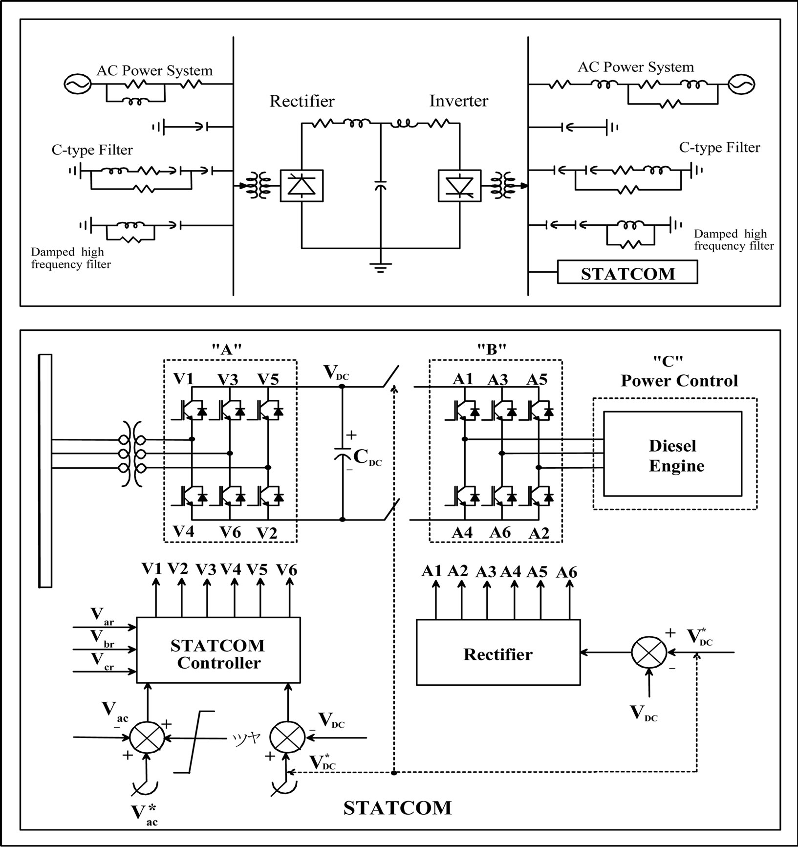
Figure 1. Configuration of proposed STATCOM system.
verter end [5-7].
The study system models a 1000 MW, 500 kV, 12 pulse, DC link with a low SCR receiving AC system. The STATCOM provides about 150 MVar at steadystate to fully compensate the inverter reactive power requirement. The simulations are conducted using the EMTDC transients simulation program.
With the STATCOM placed into the CIGRE benchmark model, the AC filter and fixed capacitor bank ratings have to be modified in order to keep the reactive power demand of the inverter. Table 1 shows the parameters of the CIGRE model used on the simulation. For the purposes of this study, the STATCOM is modeled as a two-level Voltage Source Converter, switched at 1050 Hz, and rated at ±150 Mvar.
2.3. Relation between HVDC System and STATCOM
Based on the HVDC system model of Figure 2, the mathematical model of the system is following as [4];
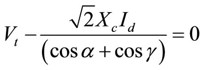
HVDC Modeling,
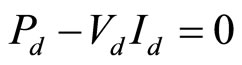 (1)
(1)
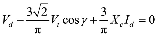 (2)
(2)
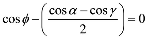 (3)
(3)
 (4)
(4)
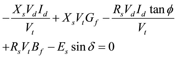
AC system Modeling,
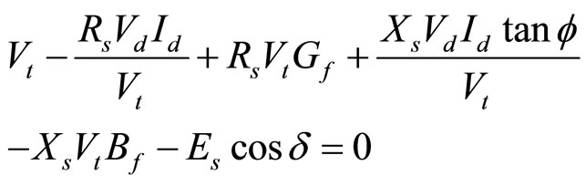 (5)
(5)
 (6)
(6)
where, the variables are:
 : Line to line voltage at the ac busbar
 : Commutation impedance
 : Dc current
 : Transformer turns ratio
 : Inverter firing angle
 : Inverter extinction angle
 : Power factor angle of inverter ac current
 : Inverter dc voltage
 : Inverter dc Power
 : Ac filter impedance,
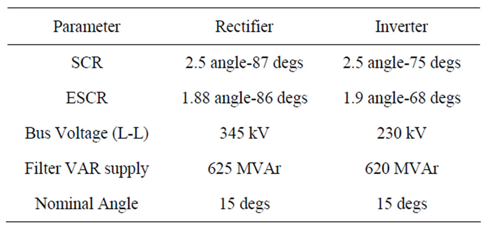
Table 1. Parameters of CIGRE model.
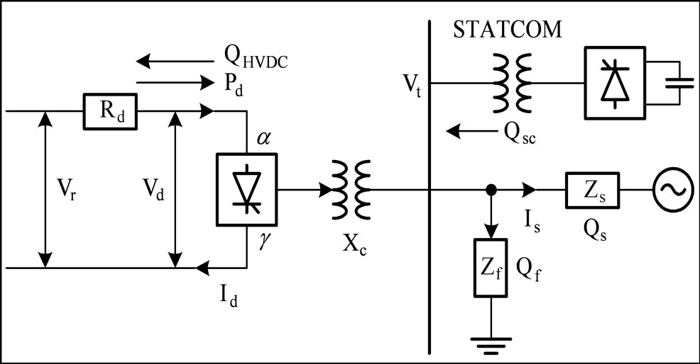
Figure 2. Inverter connected to Ac system.
 : Ac system source voltage magnitude
 : Phase angle between
  and
and 
 : Ac system impedance,
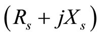
2.4. STATCOM Modeling (Figure 3)
The terminal voltage and current of the STATCOM, at the point of connection, can be modeled by a vector representation [8-10]. This vector representation is extended by a d-q model which leads to the definitions of instantaneous reactive current and active current. The voltage equations in the stationary a-b-c frame are: 
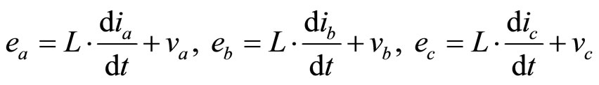 , (7)
, (7)
Also, the voltage equations in the rotating d-q frame and the input voltages in the rotating d-q frame are shown on Equation (8).
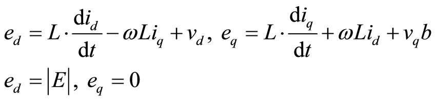 , (8)
, (8)
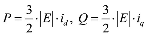
Since the active power (P) supplied from the input is directly proportional to the d-axis current  , the d-axis reference current
  is generated from the proportional and integral (PI)-type voltage controller for the DC-link voltage regulation. And the reactive power (Q) is directly proportional to the q-axis current
  , therefore, the reactive power equation and active power equation is shown in Equation (9) respectively.
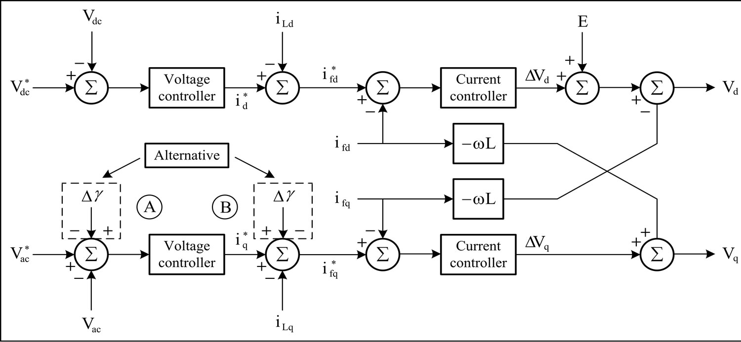
Figure 3. STATCOM controller model.
 , (9)
, (9)
The voltage equations shown in Equation (7) are transformed from the stationary a-b-c frame to the rotating d-q frame as follows:
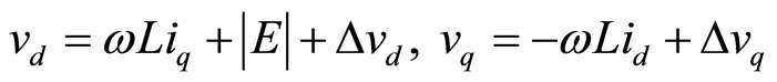 , (10)
Figure 3 shows the STATCOM control block described in this section.
2.5. Selection of Auxiliary Signal in STATCOM [7,11,12]
In HVDC control, as described in the well known CIGRE benchmark HVDC model [6], primary control parameter on rectifier side is DC current and secondary control parameter is alpha-minimum control. At the inverter side, primary control parameter is gamma-minimum control and secondary control parameter is DC current control.
In case of installing a STATCOM on the inverter side of HVDC system, a supplementary signal between HVDC and STATCOM must be considered in order to improve the coordinated performance between HVDC and STATCOM.
The following signals are candidates for suitable control coordination between HVDC and STATCOM: variations: in gamma ( ), DC current (
 ) and AC voltage (
 ). Among these signals,
  is not a good transient state control variable at the inverter end since DC current can oscillate at fundamental frequency, and actually become a sinusoid during a prolonged commutation failure. However, in the rectifier side, DC current signal could be a good control variable. Also, AC voltage as a coordinated supplementary signal can be considered, but because this signal is directly proportional to AC voltage and reactive power, its use as a control signal in the case of the STATCOM is not preferred.
Since the trajectory of  value between active power (
 ) and reactive power (
 ) in HVDC system moves according to cosine function (Figure 4). If gamma signal of HVDC is added to the controller of STATCOM, the gamma signal can be a useful signal for improving the performance of STATCOM in transient state.
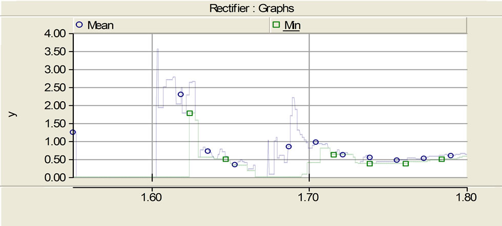
However, there are two options for employing the gamma signal: either a mean value gamma  signal or a minimum value gamma
  signal. The
  signal is more relevant for improving performance against a commutation failure, but the response time is inherently slower(when compared to the derivation of the
 ) due to the computation algorithm. On the other hand, the
  is less relevant against commutation failure, but the response time is fast. Furthermore, since the
  is always higher than
  value. This comparison is shown in Figure 5(a) for the recovery of the system following a 3-phase fault at the inverter. Figure 5(b) shows the recovery of the 3-phase AC voltages, and shows the recovery of the corresponding DC current
  and DC voltage
 .
.
Due to the relative speed of response characteristics,
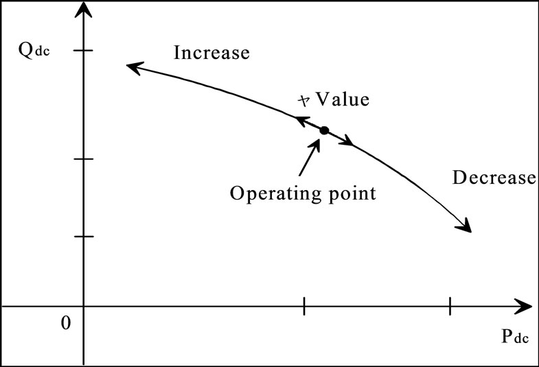
Figure 4. Trajectory between active power and reactive power in HVDC.
 (a)
(a)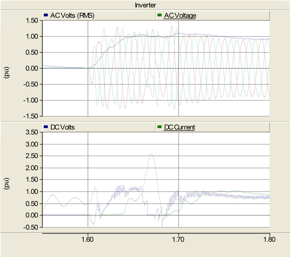 (b)
(b)
Figure 5. Recovery for 3-phase AC fault at inverter. (a) Comparison of mean value of gamma vs. minimum value of gamma; (b) Recovery of 3-phase voltages at inverter and DC voltage and DC current.
mean signal is selected as the coordinated supplementary signal of STATCOM. The supplementary signal of STATCOM is following as :
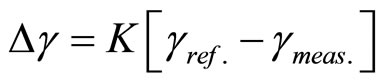 (11)
(11)
The signal which represents gamma variation, as shown in Equation (11), is added to STATCOM controller.
3. Impact of the STATCOM
The impact of the STATCOM is felt upon the following sysem aspects:
3.1. Stability Enhancement from Viewpoint of AC Network
From the viewpoint of reactive power, the relation equation of AC system is as following
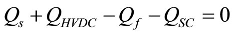 (12)
(12)
where,
 : Reactive power due to AC system impedance
 : Reactive Power consumed by HVDC
 : Reactive power by filter or capacitor
 : STATCOM
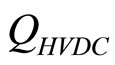
From Equation (12), if the capacity of  can covers an AC reactive power requirements, that is,
  can supply or absorbs the reactive power variations of AC system enough, it mean that Maximum Available Power (MAP) of HVDC can increases within the bounds of STATCOM control ability.
Using Equation (12) and Equations (1)-(5), MAP curve is shown in Figure 6, it shows that the capacity of STATCOM effects MAP capability as well as the voltage stability.
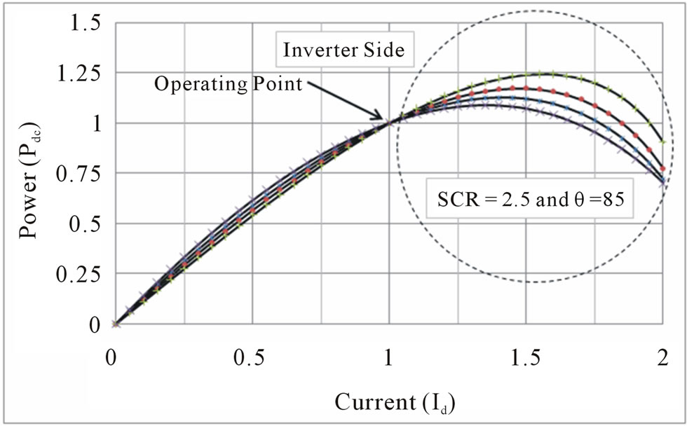
The case of Figure 6 is that STATCOM is not located in near HVDC station, but within AC system. Figure 7 shows that MAP is increased according to the location of STATCOM, which is related to the variation of AC impedance angle.
3.2. Counter-Acting Commutation Failures (CFs)
Commutation failure (CF) is one of the most frequent inverter failures in HVDC systems utilizing thyristor valves [13-16].
Before the valve can establish a forward voltage blocking capability, the internal stored charges in the valve, produced during the forward conduction interval, must be removed. Therefore, the valve requires a certain minimum negative voltage-time area, provided by the commutation margin angle, to re-establish its blocking capability.
Otherwise, the valve will immediately reconduct when it is again forward biased and that will result in an unwanted short circuit and a CF may ensue.
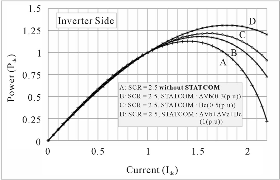
Figure 6. MAP curve according to STATCOM capacity.
 (a)
(a) (b)
(b)
Figure 7. MAP variation according to the location of STATCOM; (b) Enlargement of circle portion in figure above.
CFs can be detrimental to HVDC links. For instance, they can result in significant direct current increase and thus lead to overheating of converter valves which will shorten their lifespan. In addition, CFs can cause DC magnetic biasing in the converter transformers, and may even lead to the outage of the HVDC system. From this perspective, CFs can be considered as an index of nonavailability of the HVDC link.
A CF is a very complex phenomenon to analyze. Reference [9] proposed an empirical equation for defining CFs, as shown in Equations (13) and (14). In these equations, the possibility of CF is expressed by  which is the onset voltage of CF. Equation (13) is for a 3-phase fault case and Equation (14) is for a 1-phase fault case
 (13)
(13)
 (14)
(14)
where,  is larger DC current,
  is the impedance of converter transformer,
  is thyristor extinction angle,
  is thyristor operation angle,
  is AC voltages intersection deviation angle due to 1-phase fault. From Equation (13) and (14), larger DC current (
 ) can be re-arranged as shown in Equation (15)
 (15)
(15)
where,
 : fault clearing time
 : AC voltage after fault
 : AC voltage before fault
 : an inductance of smoothing reactor
 : an inductance of cable or overhead line
Equations (13) and (14) show that the primary reasons for CFs are current increase and the extinction angle deviations of the HVDC converter due to AC voltage reductions which can be caused by [17,18]:
• AC voltage faults/disturbances
• Transformer inrush current
• Capacitor inrush current
• Harmonic pollution or/and instability
• System induced resonances
From the above explanations, the obvious solution to reduce the risk of CFs is to maintain a constant margin angle and to maintain constant AC voltage. From Equation (14), the condition and equation for critical load variations (transformer energizing and capacitor switching etc.) to induce CFs can be shown as Equation (16).
 (16)
(16)
where,  is a short circuit capacity of equipment to connect to AC bus bar.
In this paper, several cases are simulated to show the impact of the STATCOM. The simulation conditions are as follows: SCR = 2.5 based on the CIGRE benchmark model, the capacity of STATCOM is 150 MVA and the operational set point condition is 0 MVAR (i.e. it is “floating”). And the simulation cases are with transformer energization and remote faults according to distance from the fault.
Tables 2-4 show the occurrence of CFs according to transformer energization. The STATCOM operating point is varied from 0 MVA for Table 2, lagging 50 MVA for Table 3, and leading 50 MVA for Table 4.
From Tables 2-4, as the Capacity MVA is increased from 300 to 600 MVA, CFs appear earlier without the STATCOM, i.e., at 400 MVA level. Although it is difficult to quantify the actual significance of the STATCOM in reducing the occurrence of CFs, the beneficial trends are obvious from these tables.
Table 2. CFs (Commutation Failures) according to transformer energi-zation (STATCOM: 0 MVA).
Table 3. CFs according to transformer energization (STATCOM: Lagging 50 MVA).
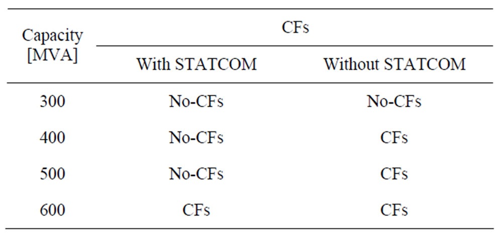
Table 4. CFs according to transformer energization (STATCOM: Leading 50 MVA).
Table 5 shows the result in case of a remote fault according to its distance from the commutating bus. The STATCOM is held in neutral mode (i.e. 0 MVA supply) for this case. With the STATCOM present, CFs are experienced at distances of 200 km or less. However, without the STATCOM, these distances have to be extended to 300 km or less. The beneficial impact of the STATCOM is evident.
Tables 6, 7 are the cases with or without the complementary control in STATCOM in operation. From Table 6, with the complementary control in STATCOM, CFs are experienced after 500 MVA capability of the transformer energization. However, without the complementary control in STATCOM, CFs are experienced at less than 450 MVA. Again the beneficial impact of the STATCOM is evident.
As shown in Table 7, the incidences of CFs with distance to a remote fault are investigated. With the STA-
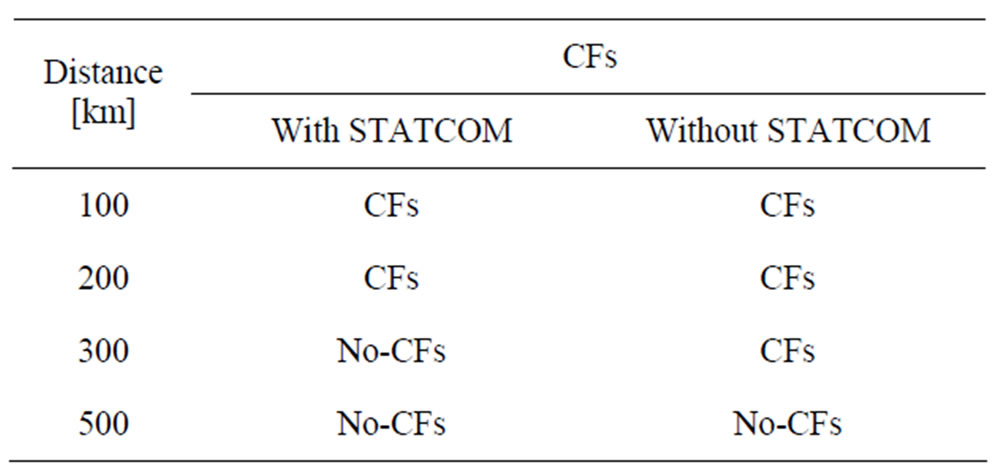
Table 5. CFs according to distance (remote faults) (STATCOM: 0 MVA).
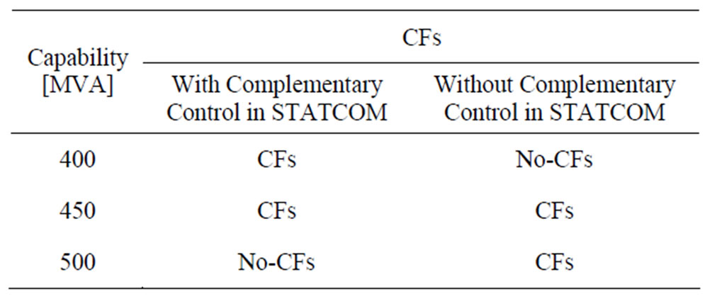
Table 6. CFs according to transformer energization (STATCOM: 0 MVA).
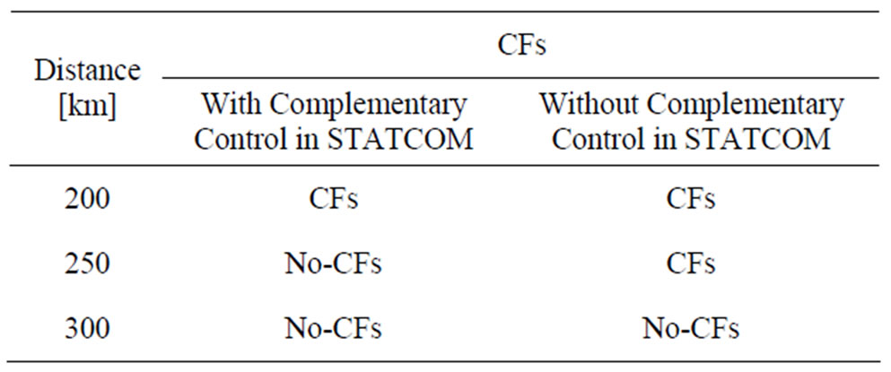
Table 7. CFs according to distance (remote faults) (STATCOM: 0 MVA).
TCOM complementary control in operation, the distance to the fault can be extended beyond 250 kms without causing CFs. However, without the STATCOM, this distance has to be increased to beyond 250 kms. Again the benefits of the STATCOM are evident.
3.3. Robustness against Harmonic Pollution
From Equations (13) and (14), the main causes of CFs are DC over-currents and AC voltage reduction. Also, AC harmonics are another major factor which can cause CFs in HVDC converters. Figure 6 conceptually shows how the extinction angle is reduced due to 3rd and 5th harmonic components in the AC voltage. The STATCOM is the designated equipment to supply reactive power to the AC network, functionally in the same manner as a synchronous condenser or a SVC, and structurally, in a similar manner to an active power filter or power conditioner. Fortunately, because a STATCOM is composed of self-commutating semiconductors, it has an inherent immunity against externally generated harmonics.
Table 8 show the reduced harmonic spectrums and the filtering capability against harmonics, in the cases that harmonics (2nd, 3rd, 5th and 7th harmonics) are arbitrarily injected in CIGRE model with and without STATCOM each other. In Table 8, 2nd harmonic is reduced to 60%, this result shows that STATCOM can contribute to stability enhancement reducing 2nd harmonic resonance condition which causes core saturation instability.
Also, two kinds of filters are normally used in HVDC systems, i.e. tuned and damped filters. Tuned filters are used for suppressing only characteristic harmonics.
On the other hand, damped filters are often employed for the suppression of both non-characteristic and characteristic harmonics. The capital cost of tuned filters is lower than for damped filters, despite the fact that a separate filter bank is required for each of the lower-order characteristic harmonics. This cost advantage is one of the reasons for the use of tuned filters.
However, the AC system has numerous other harmonic sources apart from the DC link. The AC harmonic filters play a major role in determining the waveform quality and amplitude of switching surge overvoltages on the converter bus bar. In HVDC systems, transients should be considered an integral part of the filter design for harmonic suppression. The effect on both the converter station and the existing AC system should be evaluated as part of the overall design process. Figure 7 shows fault recovery characteristics of the CIGRE HVDC model with either the damped filters or the tuned filters. The fault investigated is the recovery from a 3-phase to ground fault, which usually produces the highest overvoltages and harmonics, with the converters blocked. From Figure 7, AC network including HVDC with damped filters can have the good recovery characteristics after the fault as the same as the case with the tuned filter. Despite of the capital disadvantages, this characteristic is one of the reasons for the widespread use of tuned filters.
Consequently, if the STATCOM is connected to the
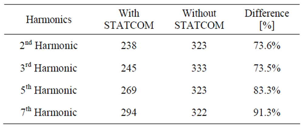
Table 8. Harmonic mitigation due to STATCOM (condition: injected harmonic current: 1000A, injected harmonics: 2nd, 3rd, 5th and 7th, measured point: AC bus terminal, target AC network: pure AC network without filters (for example: 11th, 13th filters for HVDC).
HVDC terminal, AC network with tuned filters can have the good recovery characteristics after the fault.
4. HVDC-STATCOM Simulations
4.1. Case Studies
Comparative studies of two system configurations of CIGRE model i.e. one with STATCOM and another without STATCOM were preformed. In these cases, the consideration was the converter transformer energization and its resulting saturation, which causes voltage and current distortion and repeated commutation failures at the inverter end. Results with two fault cases with either 1-phase or 3-phase faults at the inverter bus are presented below.
4.2. Results
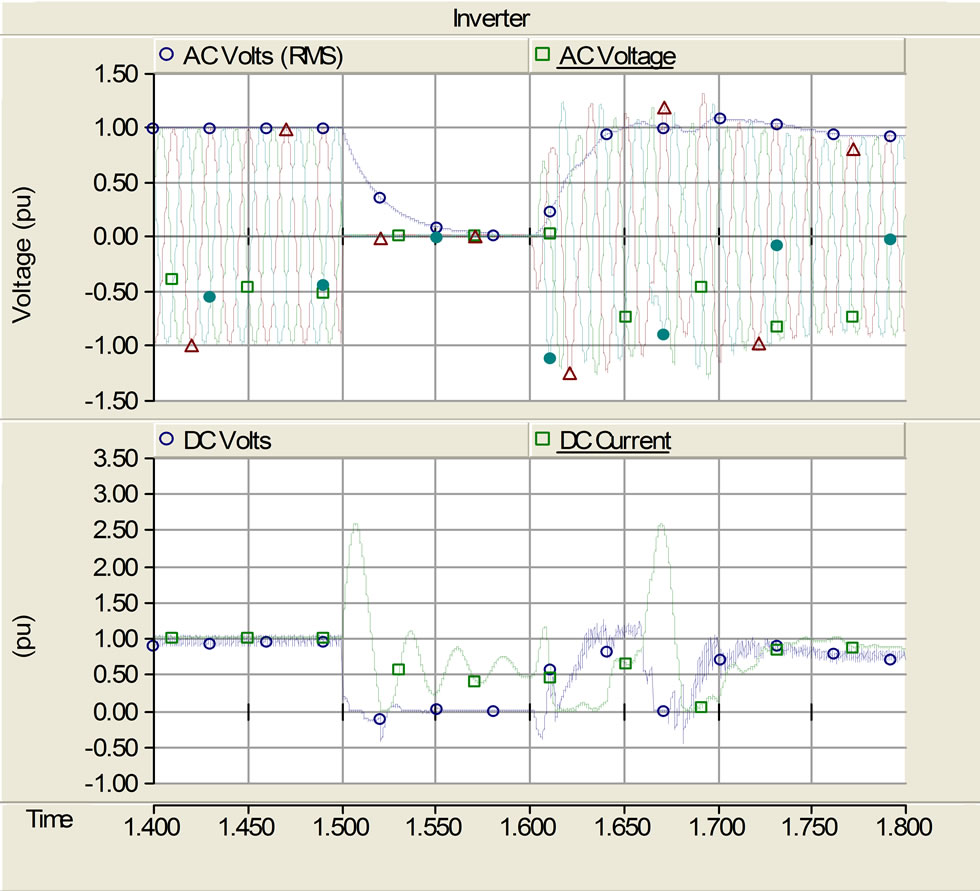
In the results that follow, the following signals are depicted: AC Voltages (3-phase instantaneous and rms values at the inverter end (Upper trace), and DC voltage and current (lower trace).
Figure 8(a) shows the case of a 3-phase fault at the inverter end on the CIGRE Model without a STATCOM. During the recovery of the HVDC system, repeated commutation failures are seen. This should be compared with Figure 8(b) where the corresponding case with the STATCOM in place is depicted. The results show that the repeated commutation failures were not observed in Figure 8(b). In this case, the impact of the STATCOM on the recovery of the recovery of the system of the system is quite conclusive.
5. Conclusions
This paper deals with the use of a STATCOM at the inverter end of a conventional HVDC system for the dynamic reactive power support. This new topology has a number of benefits. First, with the aid of an auxiliary source, this topology permits a black start feature.
The proposed scheme may be a good solution for connecting island loads, offshore oil platforms, or offshore wind farms. The proposed solution can be used with both cables and overhead lines. Second, with the reactive power coordination between STATCOM and HVDC systems, it offers a robustness for recovery from a commutation failure, and other faults on the system. Third, with the ability of the STATCOM to act as an active filter, the design of the passive filters of the HVDC system can be eased somewhat; this will enable recouping some of the costs incurred in installation of the STACOM. In this paper, the coordinated control strategy
 (a)
(a)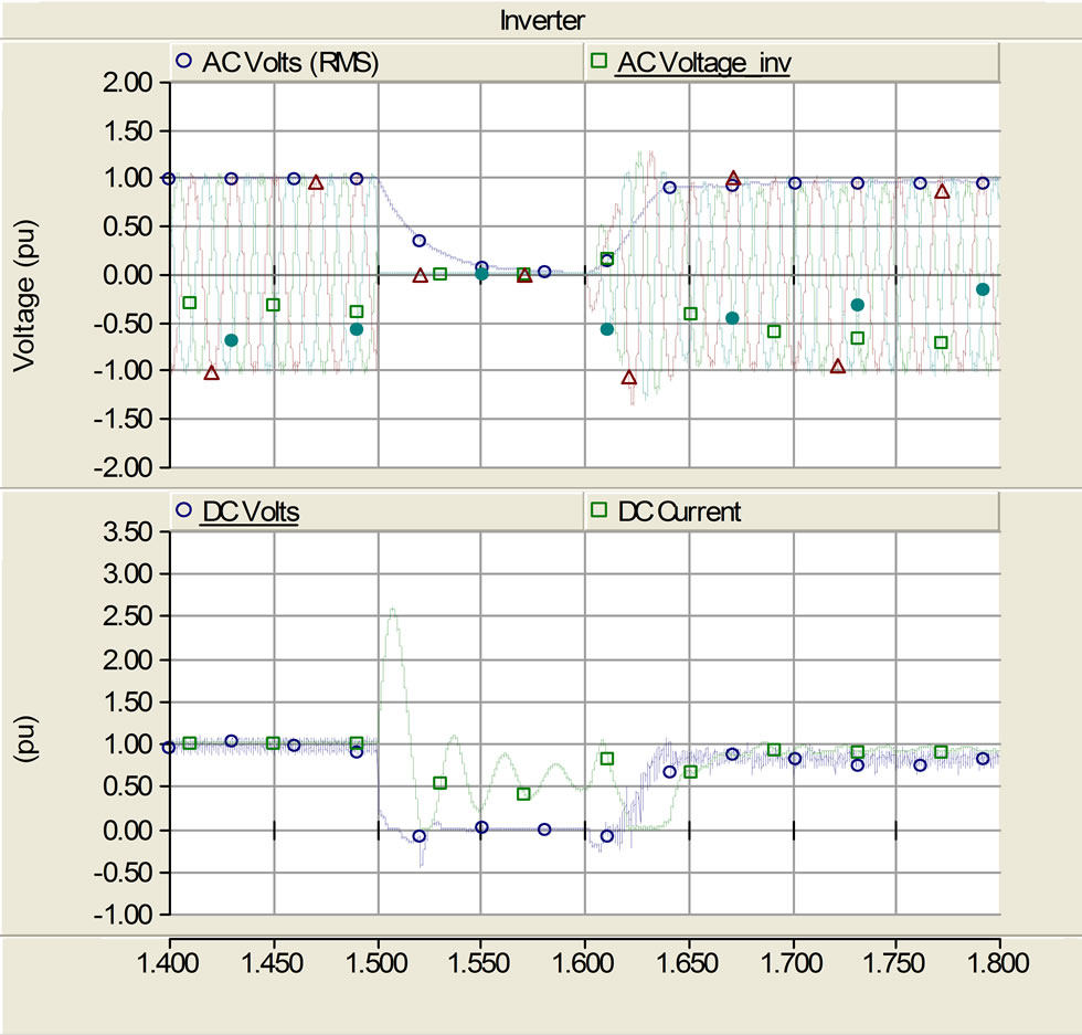 (b)
(b)
Figure 8. Response of the HVDC system in the case of considering the saturation characteristics of transformer. (At 3-phase grounded fault).
for the STATCOM-HVDC has been described.
6. REFERENCES
- C.-K. Kim, V. K. Sood, G.-S. Jang, S.-J. Lim and S.-J. Lee, “HVDC Transmission-Power Conversion Applications in Power Systems,” John Wiley & Sons (Asia) Pte Ltd., Singapore, 2009.
- B. R. Andersen and X. Lie, “Hybrid HVDC System for Power Transmission to Island Networks,” IEEE Transactions on Power Delivery, Vol. 19, No. 4, October 2004, pp. 1884-1890. doi:10.1109/TPWRD.2004.835031
- D. J. Hanson, M. L. Woodhouse, C. Horwill, D. R. Monkhouse and M. M. Osborne, “STATCOM: A New Era of Reactive Compensation,” Power Engineering Journal, Vol. 16, No. 3, June 2002, pp. 151-160. doi:10.1049/pe:20020308
- O. B. Nayak, A. M. Gole, D. G. Chapman and J. B. Davies, “Dynamic Performance of Static and Synchronous Compensators at an HVDC Inverter Bus in a Very Weak AC System,” IEEE Transactions on Power Systems, Vol. 9, No. 3, August 1994, pp. 1350-1358. doi:10.1109/59.336131
- M. O. Faruque, Y. Y. Zhang and V. Dinavahi, “Detailed Modeling of CIGRE HVDC Benchmark System Using PSCAD/EMTDC and PSB/SIMULINK,” IEEE Transactions on Power Delivery, Vol. 21, No. 1, January 2006, pp. 378-387. doi:10.1109/TPWRD.2005.852376
- M. Szechtman, T. Wess and C. V. Thio, “First Benchmark Model for HVDC Control Studied,” Electra, Vol. 135, no. 4, 1991, pp. 54-73.
- S. Nyati, S. R. Atmuri, et al., “Comparison of Voltage Control Devices at HVDC Converter Stations Connected to Weak AC Systems,” IEEE Transactions on Power Delivery, Vol. 3, No. 2, April 1998, pp. 684-693. doi:10.1109/61.4307
- K. Li, J. J. Liu, Z. A. Wang and B. Wei, “Strategies and Operating Point Optimization of STATCOM Control for Voltage Unbalance Mitigation in Three-Phase ThreeWire Systems,” IEEE Transactions on Power Delivery, Vol. 22, No. 1, January 2007, pp. 413-422. doi:10.1109/TPWRD.2006.876655
- A. Jain, K. Joshi, A. Behal and N. Mohan, “Voltage Regulation with STATCOMs: Modeling, Control and Results,” IEEE Transactions on Power Delivery, Vol. 21, No. 2, April 2006, pp. 726-735. doi:10.1109/TPWRD.2005.855489
- P. Garica-Gonzalez and A. Garcia-Cerrada, “Control System for a PWM-Based STATCOM,” IEEE Transactions on Power Delivery, Vol. 15, No. 4, October 2000, pp. 1252-1257.
- S. Tamai, et al., “Fast and Predictive HVDC Extinction angle Control,” IEEE Transactions on Power Systems, Vol. 12, no. 3, August 1997, pp. 1268-1275. doi:10.1109/59.630470
- M. Sato, K. Yamaji and M. Sekita, “Development of a Hybrid Margin Angle Controller for HVDC Continuous Operation,” IEEE Transactions on Power Systems, Vol. 11, No. 4, November 1996, pp. 1792-1798.
- Working Group 14.02, “Commutation Failures in HVDC Transmission Systems due to AC System Faults,” Electra, Vol. 169, December 1996, pp. 59-85.
- L. Zhang and L. Dofnas, “A Novel Method to Mitigate Commutation Failure in HVDC Systems,” Proceedings of IEEE Power System Technology Conference, Vol. 1, October 2002, pp. 51-56. doi:10.1109/ICPST.2002.1053503
- A. Hansen and H. Havemann, “Decreasing the Commutation Failure Frequency in HVDC Transmission Systems,” IEEE Transactions on Power Delivery, Vol. 15, No. 3, July 2000, pp. 1022-1026. doi:10.1109/61.871369
- C. V. Thio, J. B. Davies and K. L. Kent, “Commutation Failures in HVDC Transmission Systems”, IEEE Transactions on Power Delivery, Vol. 11, No. 2, April 1996, pp. 946-957. doi:10.1109/61.489356
- G. M. Kristmundsson and D. P. Carroll, “The Effect of AC System Frequency Spectrum on Commutation Failure in HVDC Inverters,” IEEE Transactions on Power Delivery, Vol. 5, No. 2, April 1990, pp. 1121-1128. doi:10.1109/61.53130
- G. Galanos, N. Vovos and G. Giannakopoulos, “Combined Control and Protection System for Improved Performance of HVDC Links in the Presence of AC Faults,” IEE Proceedings Generation, Transmission and Distribution, Vol. 131, No. 4, July 1984, pp. 129-139. doi:10.1049/ip-c.1984.0021