Intelligent Control and Automation
Vol.4 No.4(2013), Article ID:39497,7 pages DOI:10.4236/ica.2013.44041
Wireless Fault-Tolerant Controllers in Cascaded Industrial Workcells Using Wi-Fi and Ethernet
Electronics Engineering Department, American University in Cairo, Cairo, Egypt
Email: tarek.k.r@ieee.org, rdaoud@ieee.org, hamer@aucegypt.edu
Copyright © 2013 Tarek K. Refaat et al. This is an open access article distributed under the Creative Commons Attribution License, which permits unrestricted use, distribution, and reproduction in any medium, provided the original work is properly cited.
Received June 22, 2013; revised July 22, 2013; accepted July 30, 2013
Keywords: Fault Tolerance; Networked Control Systems (NCS); Industrial Informatics; Wi-Fi; Ethernet
ABSTRACT
A Wireless Networked Control System using 802.11b is used to model fault-tolerance at the controller level of an industrial workcell. The fault-tolerance study in this paper presents the cascading of two independent workcells where each controller must be able to handle the load of both cells in case of failure of the other one. The intercommunication is completely wireless between the cells and this feature is investigated. The model incorporates unmodified 802.11b and 802.11g for communication. Sensors send sampled data to both controllers and the controllers to exchange a watchdog. The fault-free and faulty models are both simulated using OPNET Network Modeler. External interference on the critical intercommunication link is also investigated. Results of simulations are presented based on a 95% confidence analysis, guaranteeing correct system performance.
1. Introduction
Wireless Networked Control System (WNCS) is a hot topic for Industrial Automation applications. Sensors (S), Actuators (A) and controllers (K) communicate using small packets and short sampling periods [1-3]. Traveling data, whether wired or wireless, must arrive on time with zero errors [1,4-6]. Protocols such as Controller Area Network (CAN) and Process Field Bus (PROFIBUS) dominated the Networked Control Systems (NCS) field in the past [7,8]. However, more recently, the NCS field was introduced to non-deterministic protocols such as Ethernet, EtherNet/IP and PROFINET [8-10]. Some Ethernet applications specifically for NCS are currently undergoing standardization with support growing from the industry [11]. Simultaneously, modifications were made to the protocol to assist its applicability to real-time NCS applications with modules such as Time-Triggered Ethernet (TT Ethernet) and Flexible Time-Triggered Ethernet (FTT Ethernet) and EtherNet/IP [10,12].
There are currently existing solutions which offer a commercially available WNCS as in [13-16]. Such systems add robustness, mobility and ease of installation and maintenance to industrial workcells [17]. One such system is described in [13], which offers a wireless communication system based on a tailored Bluetooth [18] modification. Reference [19] presents a system using unmodified 802.11b [20] and Switched Ethernet, which used the Bluetooth-based system as a benchmark. The system showed performance which met system requirements of correct packet transmission/reception and zero dropped packets in the existence of noise. While the technique of modeling noise was based on [13], another experimental noise analysis for wireless networked control systems can be found in [15]. The advantage of [19] over [13] is the use of off-the-shelf equipment and unmodified standardized protocols, while [13] offered wireless powering of the system as a trade-off.
Upon successful testing of the single-cell model, several further studies were conducted [21-23]. The study presented in [21] modeled the concatenation of two adjacent cells. The study found that a minimum inter-cell distance of 2 m was mandatory for correct operation. A safety factor of 1 m was added and all scenarios were tested at a 3 m inter-cell distance. The study was continued and the model was refined in [22] achieving concatenation at an inter-cell distance of 0 m. In both cases, two identical workcells were vertically concatenated in order to simulate/model a typical production/assembly line. Co-channel interference by neighboring nodes was studied, as well as the effect of noise from neighboring frequency bands (and other ISM nodes). The study in [21] was unable to achieve 0 m concatenation, but upon further system modification in [22], 0 m concatenation was achieved with correct system performance.
As applications of NCS become more critical, faulttolerance is required for down-time reduction. The incorporation of fault-tolerance saves large amounts of revenue due to lower downtimes, where a system, during the failure of a node, can continue operation normally while awaiting service. The system proposed in [21] was investigated for the possible incorporation of fault-tolerance at the controller level in [23]. However, the investigation was limited to a wired implementation. In this paper, wireless fault-tolerance is studied at the controller level. Two cascaded workcells employing Wi-Fi-based WNCS are simulated and analyzed after the integration of fault-tolerance at the controller level. The fault-free and faulty scenarios are studied in the absence and existence of noise from the ISM band. The main contribution of this study is that all intercommunication between the two cells is also achieved over Wi-Fi unlike previous work.
The remainder of this paper is organized as follows: Section 2 presents the background work done prior to this study. Section 3 describes the proposed model while Section 4 presents the simulated scenarios and results. Finally this research is concluded in Section 5.
2. Background
A WNCS based on the standard 802.11b protocol was studied in [19]. The system modeled a single workcell containing a number of sensors and actuators (SAs) communicating via several access points with a controller connected to the access points via Switched Ethernet.
Figure 1 shows the basic unit of the system studied in [19,21-23]. This unit is an industrial workcell, uniform 3 × 3 m, containing a total of 30 sensors, 30 actuators and 1 controller. These 60 SAs are split into two groups, 15 pairs (1:1 S:A ratio) and can be seen in the figure on the left and right of the workcell. Each group communicates, using 802.11b with an access point (AP1 and AP2), using non-interfering channels. These access points are wired, using Ethernet (802.3) to an Ethernet switch, which is wired to the controller. The communication is a 10B UDP payload, which travels from S→AP→Switch→K→Switch→AP→A.
The system was then studied in the presence of noise from the ISM band. The selection of the ISM band as interfering noise is specifically based upon results of the study conducted in [13]. The study conducted involved subjecting an ISM band-based system to interference from different sources found on the factory floor, such as spot/arc welding. The conclusion of the study showed that only directly neighboring frequencies will affect an ISM band-based system. The workcell was modeled us-
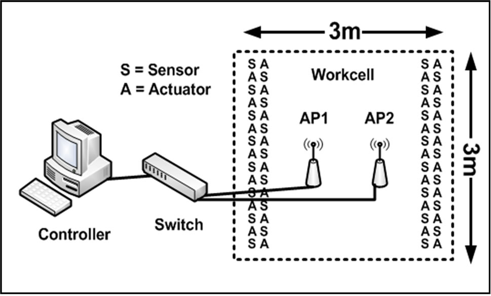
Figure 1. Single-Cell Model.
ing OPNET Network Modeler [24] and was subjected to noise of the same channels used by the system, to model the worst form of interference.
A further study conducted in [21], tested the issues regarding concatenating two identical workcells, like those modeled in [19]. The study focused on finding the minimum distance between the two cells which will allow the system to perform correctly in the vicinity of co-channel interference. The study found that a minimum distance of 2 m must exist between cells, in order to efficiently diminish the effect of co-channel interference. This 2 m inter-cell distance would only be possible after modifications are made to the system attributes, within the tunable parameters as allowed by the protocol standards. All wireless nodes should have a maximum receiver sensitivity of -50 dBm. Finally, a safety factor of 1 m was added and the inter-cell distance used for the system was 3 m.
The system was also subjected to an interfering noise study and it was found that the system cannot tolerate any interference on the reused channel. All nodes within the factory floor were denied access to that specific channel and noise was studied only on the two remaining channels. After simulations, the system was shown to perform well within a benchmark of 16 ms end-to-end delay per link (from sensor to controller or from controller to actuator) including all types of data encapsulation/de-capsulation, propagation, queuing and processing delays. These delays satisfy a benchmark which is 20% below the requirements set in [13].
In [22], a further study was conducted on the system, designed and tested in [21], in an attempt to achieve 0 m concatenation. The system designed in [21] used the standard channel deployment techniques used by the community when designing an 802.11 network. The selection of Wi-Fi channels, has a total of three non-interfering channels: 1, 6 and 11 [20]. The problem with such a deployment in the proposed system was that, with four access points, channel reuse was required and co-channel interference was a new burden on the network. The cochannel interference hindered the system’s tolerance to noise as well as adding a constraint of having a minimum inter-cell distance of 2 m. Such a frequency reuse technique was substituted with a new, unconventional channel allocation scheme, using four partially overlapping Wi-Fi channels: 1, 4, 8 and 11 [25]. The overlap would pose a threat of channel interference in normal applications, where access points are in groups of three. However, in this case, it was found that a minor channel overlap was more appropriate for a system employing four access points, with the specific design attributes given (number of nodes and payload taken into consideration) than three non-interfering channels with a single channel reused. Interference was modeled on all neighboring channels (rather than the four now reserved channels) and the system was found to be robust and tolerant to such noise.
Finally, the system of concatenated cells was taken to a further step, incorporating fault-tolerance at the controller level in [23]. Due to the availability of a second controller in the neighboring cell, concatenated in [21,22], the logical step was to take advantage of the existence of two controllers for the sake of fault-tolerance. The system was modified to accommodate the failure of either controller while maintaining correct performance within network requirements. This was accomplished by hardwiring both switches of both cells and setting all sensors to send dual samples at every sampling instant. Each sample is sent to both controllers, the sample is processed and the control word or decision is produced. Only the designated controller of the cell responds. The requirement of the processing is to ensure that if either controller fails, the other will have the most up-to-date samples needed to prepare the adequate control word or decision. The controllers also exchange a watchdog packet at half the sampling rate of the system for added reliability. The watchdog packet lets each controller know of its neighbor’s status. In the event that no watchdog packet is received, the fault-tolerant controller engages and carries both loads of the two cells, maintaining the flow of the production/assembly line until the failed controller is serviced. This process greatly reduces down-time and the system was tested in the absence and presence of ISM noise, both in the fault-free and the faulty case. The system was found to tolerate more interference during the fault case, which (while unrealistic in occurrence) is logical due to the lack of network congestion caused by the duplication of samples on the network.
The next section presents the model under study, which is based on the system designed in [23]. The main goal of the study is to attempt an integration of faulttolerance on the controller level but using the wireless medium for intercommunication between the cells, rather than a hard-wired approach as introduced in [23].
3. Proposed Model
The system proposed in [19] and further studied in [21,22] is used to design the model for this study. Two cells are concatenated at a 3 m distance, using a 1 m safety factor added to the 2 m minimum inter-cell distance. This is also to model typical cascading of cells along a production/assembly line. Each of the cells is 3 ´ 3 m, containing 30 sensors and 30 actuators. The sensors send a 10 byte packet every sampling period over UDP. The 10 bytes simulate ON/OFF control together with other position information. The data is received by the controller. After processing, the control word is sent to the actuators to be applied on the physical system (the plant). The sensors and actuators communicate via two Wi-Fi access points that are wired to an Ethernet switch. The Ethernet switch is then wired to a controller.
Figure 2 shows the proposed model and is described in what follows. The sensors and actuators are split into two groups of 15:15 (S:A) and assigned to one of the two access points. A third access point is added on the outside of the cell. This third access point is dedicated for intercommunication between the two cells. Previously, the model only required four access points, and hence used Channels 1, 6 and 11, reusing only Channel 1 [21]. Due to the increase in number of access points for the incorporation of fault-tolerance in the system, the new topology requires a new channel allocation layout which differs from previous studies.
For this study, the access points used for fault-tolerance communication operate on the same channel (Ch11), and so this channel is dedicated to these two access
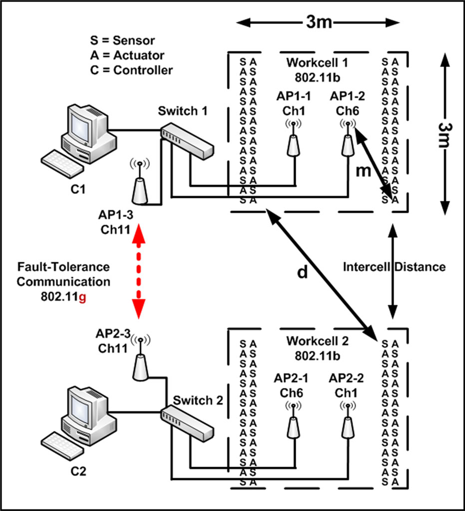
Figure 2. Proposed Model Topology.
points only. This leaves the two other non-interfering channels for the access points inside the cell. One way to address the problem would be that every workcell can be considered a unit of its own, and hence will use the three channels for each of its three access points.
The use of Channel 11 by two neighboring cells would be considered as legitimate communication, while the use of Channels 1 and 6 by neighboring cells would be considered as co-channel interference. The same analysis applied in [22] can be applied on both Channels 1 and 6.
Several Propagation/Path-Loss models are used to calculate the minimum distance between co-channel interferers as well as to find the maximum and minimum Packet Reception Power Threshold (PRPT).
The Free-space Propagation Model [26]:
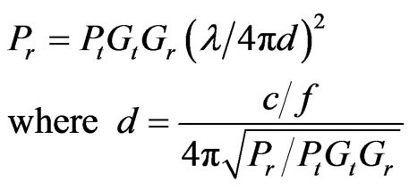 (1)
(1)
where:
 is the signal wavelength (m)
 is the speed of light (m/s)
 is the operating frequency (2.4GHz)
 isthe received signal strength (W)
 is the transmitter input power (W)
 is the receiver antenna gain
 is the transmitter antenna gain
 is the distance between transmitter and receiver (m)
One-Slope Path-Loss Model [27]:
 (2)
(2)
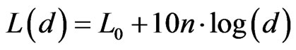
The Indoor Propagation model based on the ITU Standard [28]:
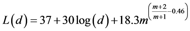 (3)
(3)
where:
 is the path loss at distance
  (dBm)
(dBm)
d is the distance between transmitter and receiver (m)
m is the number of floors along the signal’s path (0 in a factory floor case)
 is the measured path loss at distance
  (dBm)
(dBm)
 is the path loss exponent
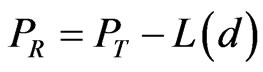 (4)
(4)
where:
 is the received signal strength (dBm)
 is the transmitter input power (dBm)
 is the path loss at distance
  (dBm)
(dBm)
Figure 2 shows the smallest distance (denoted d in the figure) possible between any two co-channel interferers. The figure does not show the 0m inter-cell distance but a generic layout for clarification. In the case that the intercell distance is 0 m, d = 2.8 m. The goal of solving these equations is to find the receiver sensitivity range within which the workcell nodes have minimal interference from its co-channel interferers and yet sensitive enough to operate correctly. The parameters such as transmit power and transmitter antenna gain can be grouped into one value (by multiplication): the physically transmitted signal strength, 1 mW. Similarly, the received signal strength and antenna gain can be grouped into one value (by division) to calculate physical received signal strength. Each equation is solved at d = 2.8 m (inter-cell distance of 0 m), finding the maximum receiver sensitivity (or minimum PRPT), above which co-channel interference would be detected. Solving Equation (1), Equation (2) and Equation (3) results in a minimum PRPT −49.0, −55.6 and −50.4 respectively. Equation (2) uses  = 40 dBm and n = 3.5, which models environment attributes nearest in similarity to a factory floor environment [27].
The equations are each re-solved at d = m = 1.8 m, the largest distance between two communicating nodes of the same workcell (denoted m in the figure). This result is the minimum receiver sensitivity, below which a node would be unable to communicate correctly with its own AP. In the same fashion as finding the minimum PRPT, the maximum PRPTs are found to be −50, −45.1 and −48.9, using Equation (1), Equation (2) and Equation (3) respectively. According to the previous results, the optimal PRPT achieving minimal co-channel interference as well as maintaining correct communication lies within −50 dBm < PRPT < −40 dBm. Any PRPT lower than −50 dBm would not sufficiently avoid co-channel interference, and any PRPT higher than −40 dBm would not allow the nodes of the same cell to correctly communicate. It is important to note that as receiver sensitivity is decreased, effects of co-channel interference decreases. However, there is a minimum sensitivity beyond which the nodes within the same cell will not be able to communicate correctly.
A similar study is conducted using OPNET Network Modeler, which uses the Free Space model as its environment. It was found that OPNET results in an optimal PRPT similar to that calculated above. However, it was found that the smallest inter-cell distance achievable was 2 m, with a PRPT of −50 dBm. Any smaller inter-cell distance would cause the system to suffer from cochannel interference. A higher PRPT would cause a loss in cell communications. The final setup consisted of a 3m inter-cell distance (adding 1m safety factor and realistic on factory floors incorporating both human and robotic assembly, permitting enough spave for maneuver) with a PRPT of −50 dBm. The value of a PRPT of −50 dBm is closest to the results of solving the Free Space equation (Equation (1) above), due to OPNET’s environment being based on Free Space.
While [22] presents a possible solution to achieve 0 m concatenation, this paper tackles the use of Channels 1, 6 and 11 at 3 m concatenation as a first step. This is due to the main focus being the wireless fault-tolerance addressed in this study, and hence it is logical to use traditional channel allocation schemes before testing newer schemes.
Figure 2 shows the channel layout for the proposed model. The access points inside the workcells, as well as the SAs use a PRPT of −50 dBm and a transmit power of 1mW as is proposed in [21,22]. The intercommunication access points use the default OPNET and commercial PRPT of −95 dBm.
In order for the system to be fault-tolerant at the controller level, each controller must be able to handle the load of both its own cell as well as the load of the other cell in the case of failure. A watchdog packet is exchanged between the two controllers at half the sampling period of all SAs. Simultaneously, all sensors send their sampled data to both controllers, so that each controller has the most up-to-date samples in case either needs to suddenly take over for the other. This is nearly a doubling of the single-cell load over the network and hence the system becomes more loaded and needs to be studied. It is important to note that this specific technique is to be used for workcells in units of two. As the number of cells increase, the system scalability is in question and each controller will handle its own load as well as that of one neighbor at max.
Due to the increase in network traffic, there is a clear bottleneck at the communication link between the two cells (Channel 11). This bottle-neck is countered using a higher data rate. The logical upgrade is 802.11g (Channel 11), which has a data rate of 54 Mbps, unlike the 11 Mbps data rate of 802.11b (Channel 1 and 6) [20].
4. Simulated Scenarios & Results
The system was designed and simulated using OPNET Network Modeler. The testing was broken down into several stages. The first scenario is the fault-free case, with both controllers fully functional and receiving samples from their own sensors as well as those of the neighboring cell. Next, one controller is failed and the remaining controller receives samples from both cells, and replies to actuators of both cells. Both scenarios are then subjected to noise in the same technique described in [19]. However, due to the reuse of Channels 1 and 6, these channels are locked as in [21] and noise is tested using Channel 11. Such a restriction would be achieved by preventing access points from broadcasting their SSIDs, using password protection and restricting the maximum number of nodes allowed to connect to the access points [21].
An alien node is rotated around the perimeter of the two cells and is made to communicate using flat FTP with one of the controllers (or the remaining controller in the faulty scenario) over Channel 11 using 802.11g. Finally, the maximum allowable FTP noise is found while maintaining the system performance. The interference must not force delays to increase beyond the set benchmark of 16 ms per link including all types of data encapsulation/de-capsulation, propagation, queuing and processing delays, and must not cause any packets to be dropped. Simulation results are presented next.
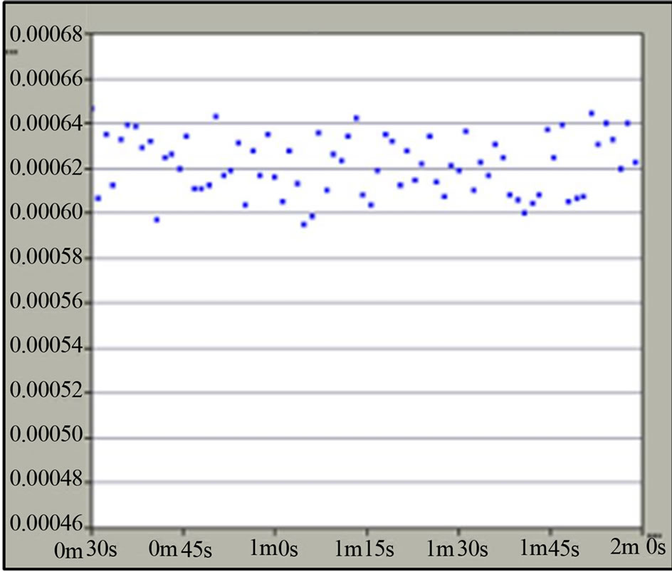
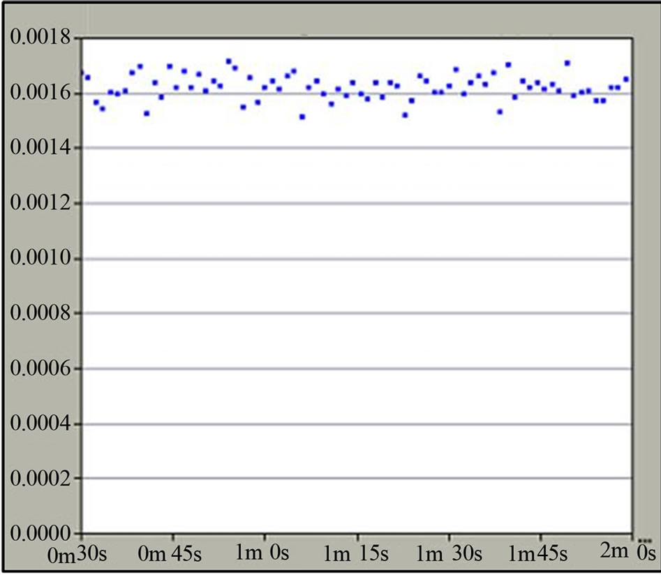
Delays are analyzed from sensor to controller, and from controller to actuator. These delays must be below the benchmark of 16 ms, set in [19,21,22], after a 95% confidence analysis. The system is shown to undergo zero packet-loss (no delayed or dropped packets over the entire communication link) while noise remains below the FTP file size thresholds shown in Table 1 compared to the single and the two-cell model without fault-tolerance. Notice the decrease in end-to-end delay in the faulty scenario which is due to the lack of duplication of samples by sensors. Figures 3(a) and (b) and Figures 4(a) and (b) show samples of delay snapshots taken from OPNET discrete event simulation results. The x-axis indicates simulation time in minutes and seconds, while the y-axis shows the end-to-end delay values in seconds. Also note the clear increase in delays in the presence of noise. Results from [19,21] are shown in the table for the sake of comparison between the current and previous works. The maximum delay is given as a range after a 95% confidence analysis.
In summary, it was proven that the WNCS under study is fault-tolerant and has no delayed or dropped packets even though the communication links between sensors, controller and actuators as well as the inter-cell link, are
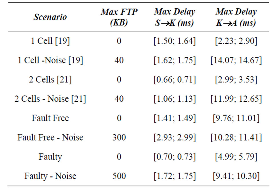
Table 1. Maximum End-to-end delay ranges [μ−∆; μ+∆].
 (a)
(a)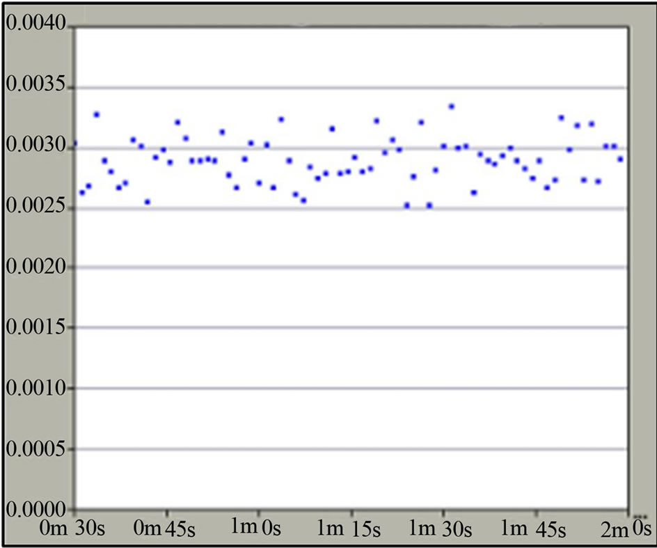 (b)
(b)
Figure 3. (a) End-to-end delay measured at the Controller, noiseless, faulty scenario. (b) End-to-end delay measured at an Actuator, noiseless, faulty scenario.
all wireless. This is an important improvement over the systems previously discussed in the literature.
5. Conclusion
This paper presented a Wireless Networked Control System which uses standard IEEE 802.11b, 802.11g and Ethernet without modifications. The main focus of the paper was the fault-tolerance at the controller level. A model was designed, where two cascaded, identical cells, containing a controller, sensors and actuators, would be able to tolerate a failure of one of the two controllers. The communication between the nodes within the cell uses 802.11b, while the inter-cell communication (a watchdog and duplicate sampled data) uses 802.11g, for increased throughput. The study also tested the effect of
 (a)
(a)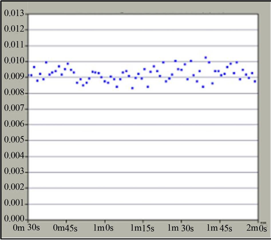 (b)
(b)
Figure 4. (a) End-to-end delay measured at the Controller, noise, faulty scenario. (b) End-to-end delay measured at an Actuator, noise, faulty scenario.
noise from neighboring ISM nodes on the system performance both in the fault-free and faulty scenarios.
All simulations were conducted using OPNET Network Modeler and it was found that the system operates within network requirements. Finally all results presented were subjected to a 95% confidence analysis.
The proposed system, compared to currently available systems, has the advantage of using unmodified standards and off-the-shelf equipment as well as being noisetolerant with no over-delayed or dropped packets. Furthermore, the functionality of the wireless inter-cell link proposed and tested in this study, makes the system facilitates topological robustness. Cells no longer need to be hard-wired to be fault-tolerant, as presented in previous work, and the results of the simulations show that utilizing a wireless inter-cell link has many advantages. The work can be further expanded upon in several ways with the most logical one being a full migration to IEEE 802.11g.
REFERENCES
- F.-L. Lian, J. R. Moyne and D. M. Tilbury, “Networked Control Systems Toolkit: A Simulation Package for Analysis and Design of Control Systems with Network Communication,” Technical Report, UM-ME-01-04, 2001. http://www.eecs.umich.edu/~impact.
- T. Skeie, S. Johannessen and C. Brunner, “Ethernet in Substation Automation,” IEEE Control Systems, Vol. 22, No. 3, 2002, pp. 43-51. http://dx.doi.org/10.1109/MCS.2002.1003998
- J. Nilsson, “Real-Time Control Systems with Delays,” PhD Thesis, Lund Institute of Technology, Lund, Sweden, 1998.
- J. D. Decotignie, “Ethernet-Based Real-Time and Industrial Communications,” Proceedings of the IEEE, Vol. 93, No. 6, 2005, pp. 1102-1117. http://dx.doi.org/10.1109/JPROC.2005.849721
- R. M. Daoud, H. M. Elsayed, H. H. Amer and S. Z. Eid, “Performance of Fast and Gigabit Ethernet in Networked Control Systems,” Proceedings of the IEEE Midwest Symposium on Circuits and Systems, MWSCAS, Cairo, December 2003, pp. 505-508.
- M. Felser, “Real-Time Ethernet-Industry Prospective,” Proceedings of the IEEE, Vol. 93, No. 6, 2005, pp. 1118- 1129. http://dx.doi.org/10.1109/JPROC.2005.849720
- Bosch, “CAN Specification Version 2.0” ISO 11898, 1991.
- Profibus and Profinet. http://www.profibus.com.
- IEEE 802.3 Standards.
- ODVA, “CIP Common, EtherNet/IP Adaptation on CIP”. http://www.odva.org/10_2/03_events/03_ethernet-homepage.htm.
- IEC 61784-1 and 61784-2. www.iec.ch.
- P. Pedreiras, L. Almeida and P. Gai, “The FTT-Ethernet Protocol: Merging Flexibility, Timeliness and Efficiency,” Proceedings of the IEEE Euromicro Conference on Real-Time Systems ECRTS, Vienna, Austria, 19-21 June 2002, pp. 134-142.
- R. Steigmann and J. Endresen, “Introduction to WISA: WISA—Wireless Interface for Sensors and Actuators,” White Paper, ABB, 2006.
- E. Toscano and L. L. Bello, “Probabilistic Feasibility Assessment of Real-Time Wireless Networks for Factory Automation with Mobile Nodes,” Proceedings of the IEEE Conference on Emerging Technologies and Factory Automation ETFA, Toulouse, 5-9 September 2011, pp. 1-8.
- L. Seno, S. Vitturi and F. Tramarin, “Experimental Evaluation of the Service Time for Industrial Hybrid (Wired/Wireless) Networks under Non-Ideal Environmental Conditions,” Proceedings of the IEEE Conference on Emerging Technologies and Factory Automation ETFA, Toulouse, September 2011, pp. 1-8.
- A. Nagy, R. Exel, P. Loschmidt and G. Gaderer, “TimeBased Localisation in Unsynchronized Wireless LAN for Industrial Automation Systems,” Proceedings of the IEEE Conference on Emerging Technologies and Factory Automation ETFA, Toulouse, 5-9 September 2011, pp. 1-8.
- S. B. Morris, “Automated Manufacturing Systems Actuators, Controls, Sensors and Robotics,” McGraw-Hill, New York, 1995.
- IEEE 802.15.1 Standard.
- T. K. Refaat, R. M. Daoud, H. H. Amer and E. A. Makled, “WiFi Implementation of Wireless Networked Control Systems,” Proceedings of the 7th IEEE International Conference on Networked Sensing Systems INSS, Kassel, Germany, 15-18 June 2010, pp. 145-148.
- IEEE 802.11 Standards.
- T. K. Refaat, R. M. Daoud, H. H. Amer, M. Hassan and O. M. Sultan, “Workcell Concatenation Using WiFiBased Wireless Networked Control Systems,” Proceedings of the 17th IEEE International Conference on Electronics, Circuits, and Systems ICECS, Athens, 12-15 December 2010.
- T. K. Refaat, R. M. Daoud, H. H. Amer and M. S. ElSoudani, “Cascading Wireless Industrial Workcells”, Proceedings of the IEEE International Conference on Mechatronics ICM, Istanbul, 13-15 April 2011.
- T. K. Refaat, E. A. Makled, R. M. Daoud, H. H. Amer and M. Hassan, “Fault-Tolerant Controllers in Adjacent Wireless Networked Control Systems Using 802.11,” Proceedings of the 3rd IEEE International Congress on Ultra Modern Telecommunications and Control Systems ICUMT, Budapest, 5-7 October 2011, pp. 1-6.
- Official site for OPNET: www.opnet.com.
- Cisco Systems, “Channel Deployment Issues for 2.4-GHz 802.11 WLANS,” 2004. http://www.cisco.com/en/US/docs/wireless/technology/channel/deployment/guide/Channel.html.
- T. S. Rappaport, “Wireless Communications: Principles and Practice,” 2nd Edition, Prentice Hall, 2002.
- S. Zvanovec, P. Pechac and M. Klepal, “Wireless LAN Networks Design: Site Survey or Propagation Modeling?” Journal of Radioengineering, Vol. 12, No. 4, 2003, pp. 42-49.
- Rec. ITU-R M.1225, “Guidelines for Evaluation of Radio Transmission Technologies for IMT-2000,” 1997. http://www.itu.int/oth/R0A0E00000C/en.