Materials Sciences and Applications
Vol.08 No.13(2017), Article ID:80944,11 pages
10.4236/msa.2017.813069
Impact Properties of Austempered Spheroidal Graphite Cast Irons
Tohru Nobuki1*, Minoru Hatate1, Toshio Shiota2
1Faculty of Engineering, Kindai University, Hiroshima, Japan
2Kindai University, Higashiosaka, Japan

Copyright © 2017 by authors and Scientific Research Publishing Inc.
This work is licensed under the Creative Commons Attribution International License (CC BY 4.0).
http://creativecommons.org/licenses/by/4.0/


Received: October 12, 2017; Accepted: December 5, 2017; Published: December 8, 2017
ABSTRACT
This study aims to clarify the influence of external notch on impact characteristics of high toughness ductile cast irons prepared by austempering heat treatment. We produced ductile cast irons samples with various matrix microstructure tested by Charpy impact within five kinds of external notches whose stress concentration factors (α), with values taken from 1.0 (Un- notched) to 4.8. In addition, to clarify the initiation process of impact characteristics, we observed the evolution of microstructure surface during bending tests with a slow loading speed for the un-notched and the notched impact samples. The results showed that the impact fracture energy decreases strongly in the range of α from 1 to 2.3 but decreases slightly for α larger than 3. Moreover, the impact value of samples with austempered microstructure is sensitive to the external notch shape. The impact transition temperature increases with increasing the stress concentration factor. The fracture energy is decreasing with the external notch from the impact test since the crack initiation energy is directly affected by this later. This work contributes to get a better understanding in the basic theories of external notch effect on impact characteristics of austempered spheroidal graphite cast irons (ADI).
Keywords:
Spheroidal Graphite Cast Irons, Austempering, Impact Characteristics, Charpy Impact Value, High Toughness

1. Introduction
Spheroidal graphite cast iron is a superior cast iron with high tensile strength, good ductility and high toughness properties which are comparable to those of steel. Therefore, spheroidal graphite cast iron is now being used as a main substitute material for cast steel or flake graphite cast iron of 600 MPa class [1] [2] [3] . As the graphite of cast iron can behave as the supplier or the absorber of C content to the matrix when heat treated, cast iron has a very valuable metallurgical characteristic that the matrix can be modified widely and easily by heat treatment in order to satisfy various engineering requirements, e.g. ferritic matrix for good ductility, pearlitic matrix high tensile strength, and austempered matrix for high tensile-strength/toughness/hardness at a same time.
Although cast iron has various superior characteristics as mentioned above, the presence of graphite causes some undesirable affection to various mechanical properties due to the decrease of the effective sectional area of matrix and producing internal notch effect [4] [5] [6] , therefore, cast iron is regarded as a material with a less anti-impact characteristic than that of steel. On the other hand, cast iron is also regarded as a material which is less sensitive against outer-notch than steel [7] , but this characteristic has not been systematically investigated so far [8] .
In order to expand the usage of cast iron in more various industrial fields, the influences of outer-notch effect on various impact characteristics and bending characteristics of cast iron are very important and need to be qualified systematically [9] [10] .
In this study, we measured the impact characteristics of austempered ductile cast iron (ADI) specimens by various external notches, and tried to clarify the effect of their induced microstructure on their impact characteristics.
2. Experimental Procedures
2.1. Materials
A high purity pig iron was melt by high frequency induction furnace. The C and Si contents were adjusted by adding carburizer at 1693 K and Fe-75%Si alloy at 1713 K, respectively. The melt for spheroidal graphite cast iron sample was spherodization-treated by adding Mg/RE/Ca/Si―spherodizer and Fe-45%Si- 8%Mg alloy. After inoculation with Fe-50%Si alloy the melts were poured into the CO2 molds into Y-blocks as indicated in Figure 1. Their matrixes were modified by three kinds of heat treatment. These heat treatment methods were listed below in Figure 2.

Figure 1. Configuration of Y-block.
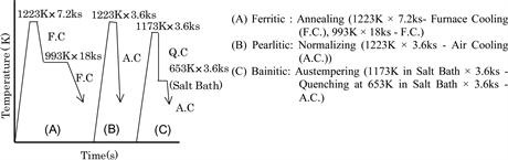
Figure 2. Method of heat treatments.
2.2. Analysis of the Microstructure and Observation of Fracture Surfaces
The microstructures of these specimens were observed with magnification of 100 X. Graphite and matrix structures, such as mean diameter, counts, area fraction, nodularity of graphite nodules and austempered matrix structures were analyzed by using the image analysis software. The fracture surfaces of tensile and impact specimens were observed by a FE-SEM.
2.3. Samples Preparation for Tensile and Impact Tests
The hardness of the test pieces was measured with Brinell hardness (10/3000/30) and the matrix hardness (HV0.5) was measured by Micro-Vickers hardness tester with values averaged from ten measurements.
Tensile testing was performed with tensile test piece with 8 mm in diameter and 28 mm in gage length using an Instron-type universal testing machine with 8.33 × 10⁻³ mm/s in crosshead speed at room temperature. Ultimate tensile strength (UTS) and elongation were determined from the results of stress-strain curves and 0.2% proof stress was estimated by the offset method of ones.
The impact testing was carried out by using an instrumented Charpy testing machine. The test was performed in the temperature range between 173 K and 423 K. Figure 3 shows the configurations of the un-notched specimens and the 5 types of notched specimens used in this study. The notch with 8 mm, 2 mm, 1 mm and 45deg.-Vshaped in root radius (R5, R1, R0.5 and R0.25, respectively) was obtained by a milling machine, and the notch with 0.15 in root radius was obtained by a wet-type cutting machine with a blade 0.3 mm thickness. The notch depth of all specimens is 2.0 mm constant so that the area of section at the notch bottom is the same in all the notched specimens. According to the Nishida’s equation [11] , stress concentration factors (α) of these specimens are 1.0 (un-notched), 1.5 (R5), 2.3 (R1), 3.0 (R0.5), 3.9 (R0.25) and 4.8 (R0.15).
3. Results and Discussion
3.1. Microstructure and Mechanical Properties
Table 1 and Figure 4 show the chemical compositions measured by emission spectro photometer using chilled sample and microstructures of specimens. The microstructure of the Austempered specimens (ADI) is upper bainite with
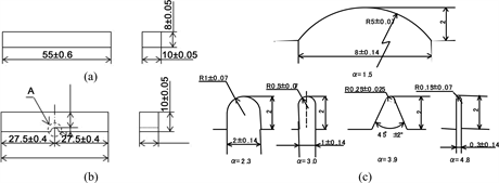
Figure 3. Shape and dimension of impact test pieces. (a) Un-notched test piece (α = 1.0), (b) Notched test piece, (c) Details of notched parts A.

Table 1. Chemical composition of ADI sample (mass%).

Figure 4. Microstructures of ADI sample.
Table 2. Mechanical properties of ADI sample.
feather-like appearance.
The mechanical properties of these specimens were shown in Table 2. The sample graphite nodularity is 90%. The tensile strength shows 1066 MPa, and the elongation shows 9.0% in ADI specimen.
3.2. Charpy impact characteristics
Figure 5 shows typical impact load-displacement curves of un-notched (α = 1.0) specimens in each ductile region. The features of the curves exhibit the characteristics of each matrix, FDI with lower load and larger displacement, PDI with higher load and smaller displacement and ADI with higher load and larger displacement, which is a similar tendency to that in tensile testing.
Figure 6 shows the ductile/brittle transition curves in Charpy impact value of ADI samples. This figure indicates that every specimen exhibits a clear transition curve, which is composed with upper shelf, transition region and lower shelf. They also indicate that addition of an external notch results in a considerable decreasing of impact value in ductile region and that the affection caused by increasing stress concentration factor (α) from 1.0 (un-notched) to 3.0.
Figure 7 shows the relation between impact transition temperature and stress

Figure 5. Chary impact curves of not only ADI, also FDI and PDI.

Figure 6. Impact transition curves of ADI sample.

Figure 7. Relation between impact transition temperature and stress concentration factor of ADI samples.

Figure 8. Relation between Charpy impact value in ductile region and stress concentration factor of ADI specimen.
concentration factor (α) of ADI specimen obtained from transition curve based on the energy transition method. The Charpy impact transition temperature is obtained from the temperature to be a half value of absorbed energy in the impact transition curve. The transition temperature increases with increasing stress concentration factor of external notch for every specimen. In fact, increasing stress concentration factor makes the stress concentration at notch root strongly increases [12] . This increment in transition temperature caused by the increase of α from 1.0 to 4.8 is about 40 K [13] .
Figure 8 shows the relation between Charpy impact value and stress concentration factor (α) at the upper shelf (ductile region). This figure indicates that the increase of α makes the impact value in ductile region decrease considerably up to α = 3, then is less concerned for higher values.
In order to evaluate the influence of notches degrees to Charpy impact values,

Figure 9. Relation between external notch factor of spheroidal graphite cast iron with various matrixes and stress concentration factor.
we defined the external notch factor by the following equation [14] :
βn = Impact value of α = 1.0 specimen/impact value of notched specimen. (1)
Figure 9 shows the relation between external notch factor (βn) and α. This figure indicates that βn increases resolutely with increase in α. The figure shows that the increasing rate of βn becomes smaller in the range of α larger than 3.0. These results suggest that additional notch with α larger than some 5 may cause only a little influence to the impact value. Since the hardest samples present the larger external notch factors, it implies that sample with a harder matrix is easier to be affected by external notches.
3.3. Observation of Crack Initiation
The specimens of ADI specimen tested with a universal testing machine, and the affections of external notch to impact energy and the initiation and propagation behavior of crack were investigated.
Figure 10 shows the microscopic observation of side view of polished ADI α=1.0 and α= 3.0 impact specimens which observed several loading point during the bending test. From these results, the main macro crack initiates at the maximum load point through micro cracks starting from the graphite edges in the stage prior to the maximum load point [15] [16] . Figure 11 shows the relation between crack length and load-displacement curves of ADI α = 1.0 and α = 3.0 specimens in bending test. The crack propagation process is strongly observed in the bending load-displacement curves. It is observed in the case of ADI specimen when notched but it is not observed when without notch process. From this result, absorbed energy (En) in impact test could separate the crack initiation energy (Ei) and the crack propagation energy (Ep) for various matrix specimens [17] . Figure 12 shows the relation between the impact characteristics of these various matrix tested at room temperature. In the case of FDI sample [15] , absorbed energy consists of a high crack initiation energy and high propagation energy.
However, for PDI [16] and ADI sample, the absorbed energy is almost constituted of crack initiation energy, because crack propagation energy is negligible. In this way, if we want to obtain higher toughness samples, the crack initiation energy need to be improved.
3.4. Impact Fracture Surfaces
Figure 13 shows the SEM observation photos of fracture surfaces of FDI [15] , PDI [16] and ADI α = 1.0 specimens in brittle, transition and ductile region of impact transition curves. In the upper shelf region, the fracture surfaces beneath the external notch root is of ductile which consists of the dimples nucleated by

Figure 10. Microscopic observation of side view of polished ADI α = 1.0 & α = 3.0 specimens in bending test.

Figure 11. Relation between crack length and bending load-displacement curves of ADI α = 1.0 specimen & α = 3.0 specimen in bending test.

Figure 12. Relation between impact characteristics for various matrixes of spheroidal graphite cast irons at R.T.

Figure 13. SEM observation photos of fracture surfaces of Ferritic (FDI), Pearlitic (PDI) and Austemperd (ADI) α = 1.0 specimen in brittle, transition and ductile region of impact test.
spheroidal graphite, and increasing of α results in no significant difference in the fracture surface appearance. In the transition region, the fracture surface is a mixture of the dimples and cleavages, and the increase of α suggests an increasing of cleavage part.
4. Conclusions
The conclusions obtained in this study are detailed as follows.
1) Charpy impact tests results show that addition of external notches to the austempered spheroidal graphite cast iron (ADI) specimens makes fracture energy in ductile region decreasing strongly.
2) Increasing the stress concentration factor (α) makes the impact transition temperature of ADI specimen increased.
3) The larger the matrix hardness sample present the larger external notch factor, which means that austempered ductile cast iron (ADI) sample specimens are easier to be affected by external notches than the case of ferritic (FDI) or pearlitic (PDI) spheroidal graphite cast iron.
4) The absorbed energy (En) which is corresponding Charpy impact value decreased with increasing of stress concentration factor because of the crack initiation energy (Ei) which is strongly decreased by the influence of the external notch.
5) Obtaining high toughness austempered ductile cast iron (ADI) requires that the crack initiation energy (Ei) is less sensitive to the external notch, thus, for a material view point design, it will be important to assign impact transition temperature at lower values.
Cite this paper
Nobuki, T., Hatate, M. and Shiota, T. (2017) Impact Properties of Austempered Spheroidal Graphite Cast Irons. Materials Sciences and Applications, 8, 948-958. https://doi.org/10.4236/msa.2017.813069
References
- 1. Keoung, J.R. and Hayrynen, K.L. (2000) Automotive Applications of Austempered Ductile Iron (ADI): A Critical Review. 2000 SAE World Congress, Technical Paper 2000-01-0764, 1-12.
- 2. Keoung, J.R., Hayrynen, K.L. and Pioszak, G.L. (2010) Designing with Austempered Ductile iron (ADI). AFS proceedings 2010, Schaumburg, paper 10-129, 1-15.
- 3. Wojciechowski, S. (2000) New Trends in the Development of Mechanical Engineering Materials. Journal of Materials Processing Technology, 106, 230-235.
https://doi.org/10.1016/S0924-0136(00)00619-1 - 4. Vasko, A. (2016) Evaluation of Shape of Graphite Particles in Cast Irons by a Shape Factor. Materials Today: Proceedings, 3, 1199-1204.
https://doi.org/10.1016/j.matpr.2016.03.006 - 5. Shiota, T. and Komatsu, S. (1978) Influences of Notch Effect and Effective Sectional Area on Fatigue Strength of Cast Irons with Various Graphite Shapes. Journal of the Society of Materials Science, JAPAN, 27, 291-297. (In Japanese)
https://doi.org/10.2472/jsms.27.291 - 6. Nobuki, T., Shiota, T., Hatate, M. and Komatsu, S. (2003) Notch Effects on Impact characteristics of spheroidal and compacted vermicular graphite cast irons with various matrix. Proceedings of the 8th Asian Foundry Congress, Bangkok, Paper 48, 97-102.
- 7. Zambrano, H.R. and Harkegard, G. (2013) Self-Arresting Cracks at Notches in Ductile Cast Iron. Engineering Fracture Mechanics, 102, 146-155.
https://doi.org/10.1016/j.engfracmech.2012.11.008 - 8. Schoenborn, S., Kaufmann, H., Sonsino, C.M. and Heim, R. (2015) Cumulative Damage of High-Strength Cast Iron Alloys for Automotive Applications. Procedia Engineering, 101, 440-449.
https://doi.org/10.1016/j.proeng.2015.02.053 - 9. D’Agostino, L., Di Cocco, V. and Iacoviello, F. (2016) Overload Effects on Fatigue Cracks in Ferritic-Pearlitic Ductile Cast Irons. Procedia Structual Integrity, 2, 3369-3376.
https://doi.org/10.1016/j.prostr.2016.06.420 - 10. Iacoviello, F., Lacoviello, D., Di Cocco, V., De Santis, A. and D’Agostino, L. (2017) Classification of Ductile Cast Iron Specimens Based on Image Analysis and Support Vector Machine. Procedia Structual Integrity, 3, 283-290.
https://doi.org/10.1016/j.prostr.2017.04.042 - 11. Nishida, M. (1967) Ouryoku Syuutyuu. Morikita Press, Japan, 572-574. (In Japanese)
- 12. Coceru, A., Capelle, J. and Pluvinage, G. (2014) On the Use of Charpy Transition Temperature as Reference Temperature for the Choice of a Pipe Steel. Engineering Failure Analysis, 37, 110-119.
https://doi.org/10.1016/j.engfailanal.2013.11.001 - 13. Kurishita, H., Kayano, H., Narui, M., Yamazaki, M., Kano, Y. and Shibahara, I. (1993) Effects of V-Notch Dimensions on Charpy Impact Test Results for Differently Sized Miniature Specimens of Ferritic Steel. Materials Transactions, 34, 1042-1052. https://doi.org/10.2320/matertrans1989.34.1042
- 14. Nobuki, T., Shiota, T. and Hatate, M. (2003) Impact Bending Characteristics of Shperoidal Graphite Cast Iron with External Notch. Proceedings of the 1st Korea-Japan Conference for YFE, Korea, 9-12.
- 15. Nobuki, T., Shiota, T. and Hatate, M. (2003) Notch Effects on Impact and Bending Characteristics of Ferritic Spheroidal Graphite and Compacted Vermicular Graphite Cast Irons. Journal of Japan Foundry Engineering Society, 75, 749-755. (In Japanese)
- 16. Nobuki, T., Shiota, T. and Hatate, M. (2004) Notch Effects on Impact and Bending Characteristics of Pearlitic Spheroidal Graphite Cast Irons. Journal of Japan Foundry Engineering Society, 76, 555-561. (In Japanese)
- 17. Kobayashi, T. (2002) Progress in the Instrumented Charpy Impact Test. Journal of the Society of Materials Science, Japan, 51, 771-779. (In Japanese)